EP1571096B1 - A transport system - Google Patents
A transport system Download PDFInfo
- Publication number
- EP1571096B1 EP1571096B1 EP20050075494 EP05075494A EP1571096B1 EP 1571096 B1 EP1571096 B1 EP 1571096B1 EP 20050075494 EP20050075494 EP 20050075494 EP 05075494 A EP05075494 A EP 05075494A EP 1571096 B1 EP1571096 B1 EP 1571096B1
- Authority
- EP
- European Patent Office
- Prior art keywords
- cage
- platform
- pair
- enclosure
- trailer
- Prior art date
- Legal status (The legal status is an assumption and is not a legal conclusion. Google has not performed a legal analysis and makes no representation as to the accuracy of the status listed.)
- Active
Links
- XAGFODPZIPBFFR-UHFFFAOYSA-N aluminium Chemical compound [Al] XAGFODPZIPBFFR-UHFFFAOYSA-N 0.000 description 3
- 229910052782 aluminium Inorganic materials 0.000 description 3
- 239000004411 aluminium Substances 0.000 description 3
- 238000000034 method Methods 0.000 description 3
- 239000007787 solid Substances 0.000 description 3
- 230000008878 coupling Effects 0.000 description 2
- 238000010168 coupling process Methods 0.000 description 2
- 238000005859 coupling reaction Methods 0.000 description 2
- 239000002360 explosive Substances 0.000 description 2
- 230000005484 gravity Effects 0.000 description 2
- 239000000463 material Substances 0.000 description 2
- 229910000831 Steel Inorganic materials 0.000 description 1
- 238000009825 accumulation Methods 0.000 description 1
- 238000013459 approach Methods 0.000 description 1
- 238000005452 bending Methods 0.000 description 1
- 238000010276 construction Methods 0.000 description 1
- 239000012530 fluid Substances 0.000 description 1
- 231100000614 poison Toxicity 0.000 description 1
- 230000007096 poisonous effect Effects 0.000 description 1
- 239000010959 steel Substances 0.000 description 1
Images


Classifications
-
- B—PERFORMING OPERATIONS; TRANSPORTING
- B65—CONVEYING; PACKING; STORING; HANDLING THIN OR FILAMENTARY MATERIAL
- B65D—CONTAINERS FOR STORAGE OR TRANSPORT OF ARTICLES OR MATERIALS, e.g. BAGS, BARRELS, BOTTLES, BOXES, CANS, CARTONS, CRATES, DRUMS, JARS, TANKS, HOPPERS, FORWARDING CONTAINERS; ACCESSORIES, CLOSURES, OR FITTINGS THEREFOR; PACKAGING ELEMENTS; PACKAGES
- B65D88/00—Large containers
- B65D88/02—Large containers rigid
- B65D88/12—Large containers rigid specially adapted for transport
- B65D88/122—Large containers rigid specially adapted for transport with access from above
- B65D88/123—Large containers rigid specially adapted for transport with access from above open top
-
- B—PERFORMING OPERATIONS; TRANSPORTING
- B60—VEHICLES IN GENERAL
- B60P—VEHICLES ADAPTED FOR LOAD TRANSPORTATION OR TO TRANSPORT, TO CARRY, OR TO COMPRISE SPECIAL LOADS OR OBJECTS
- B60P3/00—Vehicles adapted to transport, to carry or to comprise special loads or objects
- B60P3/055—Vehicles adapted to transport, to carry or to comprise special loads or objects for transporting bottles
-
- B—PERFORMING OPERATIONS; TRANSPORTING
- B65—CONVEYING; PACKING; STORING; HANDLING THIN OR FILAMENTARY MATERIAL
- B65D—CONTAINERS FOR STORAGE OR TRANSPORT OF ARTICLES OR MATERIALS, e.g. BAGS, BARRELS, BOTTLES, BOXES, CANS, CARTONS, CRATES, DRUMS, JARS, TANKS, HOPPERS, FORWARDING CONTAINERS; ACCESSORIES, CLOSURES, OR FITTINGS THEREFOR; PACKAGING ELEMENTS; PACKAGES
- B65D19/00—Pallets or like platforms, with or without side walls, for supporting loads to be lifted or lowered
- B65D19/02—Rigid pallets with side walls, e.g. box pallets
- B65D19/06—Rigid pallets with side walls, e.g. box pallets with bodies formed by uniting or interconnecting two or more components
- B65D19/08—Rigid pallets with side walls, e.g. box pallets with bodies formed by uniting or interconnecting two or more components made wholly or mainly of metal
-
- B—PERFORMING OPERATIONS; TRANSPORTING
- B65—CONVEYING; PACKING; STORING; HANDLING THIN OR FILAMENTARY MATERIAL
- B65D—CONTAINERS FOR STORAGE OR TRANSPORT OF ARTICLES OR MATERIALS, e.g. BAGS, BARRELS, BOTTLES, BOXES, CANS, CARTONS, CRATES, DRUMS, JARS, TANKS, HOPPERS, FORWARDING CONTAINERS; ACCESSORIES, CLOSURES, OR FITTINGS THEREFOR; PACKAGING ELEMENTS; PACKAGES
- B65D19/00—Pallets or like platforms, with or without side walls, for supporting loads to be lifted or lowered
- B65D19/38—Details or accessories
- B65D19/385—Frames, corner posts or pallet converters, e.g. for facilitating stacking of charged pallets
-
- B—PERFORMING OPERATIONS; TRANSPORTING
- B65—CONVEYING; PACKING; STORING; HANDLING THIN OR FILAMENTARY MATERIAL
- B65D—CONTAINERS FOR STORAGE OR TRANSPORT OF ARTICLES OR MATERIALS, e.g. BAGS, BARRELS, BOTTLES, BOXES, CANS, CARTONS, CRATES, DRUMS, JARS, TANKS, HOPPERS, FORWARDING CONTAINERS; ACCESSORIES, CLOSURES, OR FITTINGS THEREFOR; PACKAGING ELEMENTS; PACKAGES
- B65D88/00—Large containers
- B65D88/02—Large containers rigid
- B65D88/12—Large containers rigid specially adapted for transport
- B65D88/127—Large containers rigid specially adapted for transport open-sided container, i.e. having substantially the whole side free to provide access, with or without closures
-
- B—PERFORMING OPERATIONS; TRANSPORTING
- B65—CONVEYING; PACKING; STORING; HANDLING THIN OR FILAMENTARY MATERIAL
- B65D—CONTAINERS FOR STORAGE OR TRANSPORT OF ARTICLES OR MATERIALS, e.g. BAGS, BARRELS, BOTTLES, BOXES, CANS, CARTONS, CRATES, DRUMS, JARS, TANKS, HOPPERS, FORWARDING CONTAINERS; ACCESSORIES, CLOSURES, OR FITTINGS THEREFOR; PACKAGING ELEMENTS; PACKAGES
- B65D2519/00—Pallets or like platforms, with or without side walls, for supporting loads to be lifted or lowered
- B65D2519/00004—Details relating to pallets
- B65D2519/00009—Materials
- B65D2519/00014—Materials for the load supporting surface
- B65D2519/00024—Metal
-
- B—PERFORMING OPERATIONS; TRANSPORTING
- B65—CONVEYING; PACKING; STORING; HANDLING THIN OR FILAMENTARY MATERIAL
- B65D—CONTAINERS FOR STORAGE OR TRANSPORT OF ARTICLES OR MATERIALS, e.g. BAGS, BARRELS, BOTTLES, BOXES, CANS, CARTONS, CRATES, DRUMS, JARS, TANKS, HOPPERS, FORWARDING CONTAINERS; ACCESSORIES, CLOSURES, OR FITTINGS THEREFOR; PACKAGING ELEMENTS; PACKAGES
- B65D2519/00—Pallets or like platforms, with or without side walls, for supporting loads to be lifted or lowered
- B65D2519/00004—Details relating to pallets
- B65D2519/00009—Materials
- B65D2519/00049—Materials for the base surface
- B65D2519/00059—Metal
-
- B—PERFORMING OPERATIONS; TRANSPORTING
- B65—CONVEYING; PACKING; STORING; HANDLING THIN OR FILAMENTARY MATERIAL
- B65D—CONTAINERS FOR STORAGE OR TRANSPORT OF ARTICLES OR MATERIALS, e.g. BAGS, BARRELS, BOTTLES, BOXES, CANS, CARTONS, CRATES, DRUMS, JARS, TANKS, HOPPERS, FORWARDING CONTAINERS; ACCESSORIES, CLOSURES, OR FITTINGS THEREFOR; PACKAGING ELEMENTS; PACKAGES
- B65D2519/00—Pallets or like platforms, with or without side walls, for supporting loads to be lifted or lowered
- B65D2519/00004—Details relating to pallets
- B65D2519/00009—Materials
- B65D2519/00154—Materials for the side walls
- B65D2519/00164—Metal
-
- B—PERFORMING OPERATIONS; TRANSPORTING
- B65—CONVEYING; PACKING; STORING; HANDLING THIN OR FILAMENTARY MATERIAL
- B65D—CONTAINERS FOR STORAGE OR TRANSPORT OF ARTICLES OR MATERIALS, e.g. BAGS, BARRELS, BOTTLES, BOXES, CANS, CARTONS, CRATES, DRUMS, JARS, TANKS, HOPPERS, FORWARDING CONTAINERS; ACCESSORIES, CLOSURES, OR FITTINGS THEREFOR; PACKAGING ELEMENTS; PACKAGES
- B65D2519/00—Pallets or like platforms, with or without side walls, for supporting loads to be lifted or lowered
- B65D2519/00004—Details relating to pallets
- B65D2519/00009—Materials
- B65D2519/00223—Materials for the corner elements or corner frames
- B65D2519/00233—Metal
-
- B—PERFORMING OPERATIONS; TRANSPORTING
- B65—CONVEYING; PACKING; STORING; HANDLING THIN OR FILAMENTARY MATERIAL
- B65D—CONTAINERS FOR STORAGE OR TRANSPORT OF ARTICLES OR MATERIALS, e.g. BAGS, BARRELS, BOTTLES, BOXES, CANS, CARTONS, CRATES, DRUMS, JARS, TANKS, HOPPERS, FORWARDING CONTAINERS; ACCESSORIES, CLOSURES, OR FITTINGS THEREFOR; PACKAGING ELEMENTS; PACKAGES
- B65D2519/00—Pallets or like platforms, with or without side walls, for supporting loads to be lifted or lowered
- B65D2519/00004—Details relating to pallets
- B65D2519/00258—Overall construction
- B65D2519/00263—Overall construction of the pallet
- B65D2519/00273—Overall construction of the pallet made of more than one piece
-
- B—PERFORMING OPERATIONS; TRANSPORTING
- B65—CONVEYING; PACKING; STORING; HANDLING THIN OR FILAMENTARY MATERIAL
- B65D—CONTAINERS FOR STORAGE OR TRANSPORT OF ARTICLES OR MATERIALS, e.g. BAGS, BARRELS, BOTTLES, BOXES, CANS, CARTONS, CRATES, DRUMS, JARS, TANKS, HOPPERS, FORWARDING CONTAINERS; ACCESSORIES, CLOSURES, OR FITTINGS THEREFOR; PACKAGING ELEMENTS; PACKAGES
- B65D2519/00—Pallets or like platforms, with or without side walls, for supporting loads to be lifted or lowered
- B65D2519/00004—Details relating to pallets
- B65D2519/00258—Overall construction
- B65D2519/00283—Overall construction of the load supporting surface
- B65D2519/00288—Overall construction of the load supporting surface made of one piece
-
- B—PERFORMING OPERATIONS; TRANSPORTING
- B65—CONVEYING; PACKING; STORING; HANDLING THIN OR FILAMENTARY MATERIAL
- B65D—CONTAINERS FOR STORAGE OR TRANSPORT OF ARTICLES OR MATERIALS, e.g. BAGS, BARRELS, BOTTLES, BOXES, CANS, CARTONS, CRATES, DRUMS, JARS, TANKS, HOPPERS, FORWARDING CONTAINERS; ACCESSORIES, CLOSURES, OR FITTINGS THEREFOR; PACKAGING ELEMENTS; PACKAGES
- B65D2519/00—Pallets or like platforms, with or without side walls, for supporting loads to be lifted or lowered
- B65D2519/00004—Details relating to pallets
- B65D2519/00258—Overall construction
- B65D2519/00313—Overall construction of the base surface
- B65D2519/00323—Overall construction of the base surface made of more than one piece
-
- B—PERFORMING OPERATIONS; TRANSPORTING
- B65—CONVEYING; PACKING; STORING; HANDLING THIN OR FILAMENTARY MATERIAL
- B65D—CONTAINERS FOR STORAGE OR TRANSPORT OF ARTICLES OR MATERIALS, e.g. BAGS, BARRELS, BOTTLES, BOXES, CANS, CARTONS, CRATES, DRUMS, JARS, TANKS, HOPPERS, FORWARDING CONTAINERS; ACCESSORIES, CLOSURES, OR FITTINGS THEREFOR; PACKAGING ELEMENTS; PACKAGES
- B65D2519/00—Pallets or like platforms, with or without side walls, for supporting loads to be lifted or lowered
- B65D2519/00004—Details relating to pallets
- B65D2519/00258—Overall construction
- B65D2519/00492—Overall construction of the side walls
- B65D2519/00532—Frame structures
-
- B—PERFORMING OPERATIONS; TRANSPORTING
- B65—CONVEYING; PACKING; STORING; HANDLING THIN OR FILAMENTARY MATERIAL
- B65D—CONTAINERS FOR STORAGE OR TRANSPORT OF ARTICLES OR MATERIALS, e.g. BAGS, BARRELS, BOTTLES, BOXES, CANS, CARTONS, CRATES, DRUMS, JARS, TANKS, HOPPERS, FORWARDING CONTAINERS; ACCESSORIES, CLOSURES, OR FITTINGS THEREFOR; PACKAGING ELEMENTS; PACKAGES
- B65D2519/00—Pallets or like platforms, with or without side walls, for supporting loads to be lifted or lowered
- B65D2519/00004—Details relating to pallets
- B65D2519/00547—Connections
- B65D2519/00577—Connections structures connecting side walls, including corner posts, to each other
- B65D2519/00616—Connections structures connecting side walls, including corner posts, to each other structures not intended to be disassembled
- B65D2519/00626—Connections structures connecting side walls, including corner posts, to each other structures not intended to be disassembled sidewalls connected via corner posts
-
- B—PERFORMING OPERATIONS; TRANSPORTING
- B65—CONVEYING; PACKING; STORING; HANDLING THIN OR FILAMENTARY MATERIAL
- B65D—CONTAINERS FOR STORAGE OR TRANSPORT OF ARTICLES OR MATERIALS, e.g. BAGS, BARRELS, BOTTLES, BOXES, CANS, CARTONS, CRATES, DRUMS, JARS, TANKS, HOPPERS, FORWARDING CONTAINERS; ACCESSORIES, CLOSURES, OR FITTINGS THEREFOR; PACKAGING ELEMENTS; PACKAGES
- B65D2519/00—Pallets or like platforms, with or without side walls, for supporting loads to be lifted or lowered
- B65D2519/00004—Details relating to pallets
- B65D2519/00547—Connections
- B65D2519/00671—Connections structures connecting corner posts to the pallet
- B65D2519/00701—Structures not intended to be disassembled
-
- B—PERFORMING OPERATIONS; TRANSPORTING
- B65—CONVEYING; PACKING; STORING; HANDLING THIN OR FILAMENTARY MATERIAL
- B65D—CONTAINERS FOR STORAGE OR TRANSPORT OF ARTICLES OR MATERIALS, e.g. BAGS, BARRELS, BOTTLES, BOXES, CANS, CARTONS, CRATES, DRUMS, JARS, TANKS, HOPPERS, FORWARDING CONTAINERS; ACCESSORIES, CLOSURES, OR FITTINGS THEREFOR; PACKAGING ELEMENTS; PACKAGES
- B65D2519/00—Pallets or like platforms, with or without side walls, for supporting loads to be lifted or lowered
- B65D2519/00004—Details relating to pallets
- B65D2519/00736—Details
- B65D2519/00776—Accessories for manipulating the pallet
- B65D2519/00796—Guiding means for fork-lift
-
- B—PERFORMING OPERATIONS; TRANSPORTING
- B65—CONVEYING; PACKING; STORING; HANDLING THIN OR FILAMENTARY MATERIAL
- B65D—CONTAINERS FOR STORAGE OR TRANSPORT OF ARTICLES OR MATERIALS, e.g. BAGS, BARRELS, BOTTLES, BOXES, CANS, CARTONS, CRATES, DRUMS, JARS, TANKS, HOPPERS, FORWARDING CONTAINERS; ACCESSORIES, CLOSURES, OR FITTINGS THEREFOR; PACKAGING ELEMENTS; PACKAGES
- B65D2519/00—Pallets or like platforms, with or without side walls, for supporting loads to be lifted or lowered
- B65D2519/00004—Details relating to pallets
- B65D2519/00736—Details
- B65D2519/00935—Details with special means for nesting or stacking
- B65D2519/00955—Details with special means for nesting or stacking stackable
- B65D2519/00965—Details with special means for nesting or stacking stackable when loaded
- B65D2519/00975—Details with special means for nesting or stacking stackable when loaded through the side walls
-
- B—PERFORMING OPERATIONS; TRANSPORTING
- B65—CONVEYING; PACKING; STORING; HANDLING THIN OR FILAMENTARY MATERIAL
- B65D—CONTAINERS FOR STORAGE OR TRANSPORT OF ARTICLES OR MATERIALS, e.g. BAGS, BARRELS, BOTTLES, BOXES, CANS, CARTONS, CRATES, DRUMS, JARS, TANKS, HOPPERS, FORWARDING CONTAINERS; ACCESSORIES, CLOSURES, OR FITTINGS THEREFOR; PACKAGING ELEMENTS; PACKAGES
- B65D88/00—Large containers
- B65D88/02—Large containers rigid
- B65D88/022—Large containers rigid in multiple arrangement, e.g. stackable, nestable, connected or joined together side-by-side
-
- B—PERFORMING OPERATIONS; TRANSPORTING
- B65—CONVEYING; PACKING; STORING; HANDLING THIN OR FILAMENTARY MATERIAL
- B65D—CONTAINERS FOR STORAGE OR TRANSPORT OF ARTICLES OR MATERIALS, e.g. BAGS, BARRELS, BOTTLES, BOXES, CANS, CARTONS, CRATES, DRUMS, JARS, TANKS, HOPPERS, FORWARDING CONTAINERS; ACCESSORIES, CLOSURES, OR FITTINGS THEREFOR; PACKAGING ELEMENTS; PACKAGES
- B65D90/00—Component parts, details or accessories for large containers
- B65D90/004—Contents retaining means
-
- F—MECHANICAL ENGINEERING; LIGHTING; HEATING; WEAPONS; BLASTING
- F17—STORING OR DISTRIBUTING GASES OR LIQUIDS
- F17C—VESSELS FOR CONTAINING OR STORING COMPRESSED, LIQUEFIED OR SOLIDIFIED GASES; FIXED-CAPACITY GAS-HOLDERS; FILLING VESSELS WITH, OR DISCHARGING FROM VESSELS, COMPRESSED, LIQUEFIED, OR SOLIDIFIED GASES
- F17C2205/00—Vessel construction, in particular mounting arrangements, attachments or identifications means
- F17C2205/01—Mounting arrangements
- F17C2205/0103—Exterior arrangements
- F17C2205/0107—Frames
Definitions
- the present invention relates to a transport system, and in particular a transport system for use with gas cylinders such as low pressure gas (LPG) cylinders.
- gas cylinders such as low pressure gas (LPG) cylinders.
- LPG cylinders are individually stacked onto trailers.
- a base layer is initially laid, onto the top of which a number of wooden battons are laid, such that a second layer of LPG cylinders can be stacked on top of the base layer. This process may then be repeated until the trailer has been filled or the desired number of LPG cylinders has been loaded.
- the trailer is cage-like in construction and has gates along its side and rear so that the cylinders can be loaded on and off the trailer from any point.
- EP-A-1204573 discloses a freight container having a base 2 and roof 5 is provided with fitting means 8 and 9 on the roof and a movable support strut 24.
- the support strut 24 is provided and can be moved from a loading position ( Fig 2 ) to a load bearing position ( Fig 1 ) between filling means 8 and 9 and the container base 5.
- the support strut 24 can be hingedly fixed to a corner post 21 of the container.
- the support strut can be part of a gate 20 hingedly fixed to a corner post.
- the support strut 24 may be substantially vertical.
- Locking means ( Fig 4 -6) are provided to lock the support strut 24 in the load bearing position.
- the fitting means 8 and 9 on the roof are provided to allow the container to be lifted and/or stacked (Fig 8-11).
- Two fitting means 8 and 9 are provided on each side wall and fixed proximate a junction of the roof 5 and side walls 3 and 4 of the container and separated by a predetermined distance of less than the side wall of the container, preferably 12.2m-
- a roof beam (12, Fig 3 ) may be provided to connect fitting means on opposed sidewalls.
- the present invention therefore provides a transport system according to claim 1.
- each cage comprises a base defining at least a pair of channels shaped and dimensioned for receiving a pair of tines of a forklift.
- each cage comprises a frame extending from the base, at least one upper edge of the frame having one of a male or a female member, and a corresponding other of the male or female member is provided on an underside of the base.
- each pair of male and female members are self aligning.
- the male and female members each have a substantially V shaped cross section.
- the frame may be opened outwardly on at least one side of the cage.
- the enclosure comprises at least a pair of opposing uprights independently moveable relative to the platform.
- the enclosure comprises an upper rail and a lower rail, each of which rails are disposed substantially parallel to the platform, the or each upright being slidably mounted to the upper and the lower rail.
- the enclosure comprises a pair of opposed upper rails and a pair of opposed lower rails.
- the or each lower rail is formed integrally with the platform.
- the or each upright may be locked in position relative to the platform.
- the retaining means comprises at least a pair of dividers projecting upwardly from the platform.
- the enclosure is mobile.
- the enclosure is a vehicular trailer.
- cage is intended to mean any enclosure which is capable of retaining one or more objects therein, which cage need not be closed on all sides, and which is preferably comprised of substantially open framework, but could equally comprise one or more substantially solid surfaces such as to be in the form of a box or the like.
- the term "container” is intended to mean a vessel capable of retaining a fluid therein, and is particularly intended to mean a pressure tight vessel such as a gas cylinder or the like.
- the term "upright” is intended to mean a beam or post or the like, which need not be disposed in a vertical orientation, but which in use is preferably substantially vertically disposed.
- channel is intended to mean an open or closed recess or aperture which is capable of receiving a forklift tine or the like, which channel could be formed integrally with a body as a through or blind aperture, or could be formed as a depression in a surface of a body.
- self aligning is intended to mean the ability of two co-operating components such as male and female components, to substantially align and locate themselves in complete engagement with one another once brought into initial alignment with one another, this self alignment preferably but not essentially being aided by gravity forcing the co-operating components together.
- a transport system for particular use in loading, transporting and/or storing, in safety and with greater efficiency than was previously possible, large numbers of objects, in particular containers such as gas cylinders which, in the preferred embodiment illustrated, take the form of conventional cylinders 44 and elongate cylinders 46. It will however be appreciated that the system 10 could be adapted for use with any number of other objects or containers (not shown).
- the system 10 consist primarily of a preferably mobile enclosure in the form of a trailer 12, in addition to a variety of cages, and in the preferred embodiment illustrated, a conventional cage 14 and an elongate cage 114, for use with the conventional cylinders 44 and the elongate cylinders 46 respectively.
- a plurality of the cages 14, 114 are loaded onto, and secured within, the trailer 12, as will be described in greater detail hereinafter.
- the conventional cages 14 and elongate cages 114 are similar in configuration and operation, and thus like components have been accorded like reference numerals, and unless otherwise stated, perform a like function.
- the primary difference between the conventional cage 14 and the elongate cage 114 is the difference in height, the elongate cage 114 being approximately twice the height of the conventional cage 14 in order to be capable of housing the elongate cylinders 46.
- the conventional cage 14 comprises a pallet-like base 16 having four sides, a top surface and an underside, the base 16 preferably being formed from box section aluminium, or any other suitable material.
- a frame 20 Extending from the extremity of the base 16 is a frame 20, again preferably formed from aluminium or the like, the frame 20 extending above the tops of the conventional cylinders 44, the reason for which will be described in detail hereinafter.
- the frame 20 again has four sides, corresponding to those of the base 16.
- the conventional cage 14 includes a gate 22 removably secured thereto, which gate 22, upon removal, facilitates ease of loading of the conventional cage 14 with the conventional cylinders 44. Once the conventional cage 14 has been filled with the conventional cylinders 44, the gate 22 is replaced and secured in place on the frame 20, in order to prevent the conventional cylinders 44 from falling from the conventional cage 14, in particular during transit.
- the base 16 includes at least one pair, and in the embodiment illustrated, two pairs, of channels 18 extending internally thereof.
- the channels 18 are shaped and dimensioned to receive the tines (not shown) of a forklift (not shown) or the like, in order to manoeuvre the filled (or empty) cages 14 onto or off the trailer 12, as described in detail hereinafter.
- alternative means could be provided to facilitate lifting of the cage 14, 114 for loading and/or unloading purposes.
- the cage 14, 114 could be provided with one or more suitably located lifting eyes (not shown) in order to allow the cage 14, 114 to be lifted and manoeuvred using a crane or the like.
- the frame 20 incorporates a pair of opposed cross-beams 24 which are disposed just above the top of the conventional cylinders 44, such as to define a pair of upper edges of the frame 20.
- the pair of cross-beams 24 therefore allow two or more cages 14 to be stacked one on top of the other, in particular on the trailer 12, although additionally at a depot (not shown) or similar storage facility.
- a male member 48 is formed integrally with the upper surface of each cross beam 24, and in the preferred embodiment illustrated is triangular or V shaped in cross-section.
- each base 16 is therefore provided with a correspondingly shaped and located female member or recess (not shown), into which the male member 48 is engaged when one cage 14 is stacked on top of another.
- the interlocking configuration of the male members 48 and the corresponding female members (not shown) provide increased stability to two or more cages 14 stacked one on top of the other. This is particularly advantageous when transporting the filled cages 14 on the trailer 12, but additionally if the filled cages 14 are stacked for storage at an outdoor depot or the like, and consequently exposed to high winds or minor collisions by forklifts or other vehicles or machinery.
- each male member 48 could be in the form of one or more upstanding studs (not shown), cylindrical or otherwise, with the female member (not shown) then taking the form of a correspondingly shaped and dimensioned aperture (not shown) for receiving said stud.
- V-shaped cross section for both the male member 48 and the female member (not shown) allows for greater tolerances when aligning one cage 14 on top of another cage 14 for stacking, as the V-shaped male member 48 and female member (not shown) will tend to guide one another into the fully engaged position, in particular under the influence of gravity acting to force the upper cage 14 downwardly onto the lower cage 14, thereby facilitating the self alignment of the cages 14.
- the elongate cages 114 again include a pallet-like base 116, from the periphery of which extends a frame 120.
- the base incorporates two pairs of channels 118, and the frame 120 is provided with a releasably secured gate 122 in order to facilitate the filling of the cage 114.
- the gate 122 could be omitted, with the cage 114 then being loaded from the open top thereof.
- Each frame 120 again includes a pair of opposed cross-beams 124, atop each of which is located a male member 148.
- the trailer 12 consists of a platform 26 having four sides, which platform 26, in the preferred embodiment illustrated, is the bed of the trailer 12, extending upwardly from either side of which are a plurality of uprights 32, preferably formed from box section steel or aluminium or any other suitable material.
- the trailer 12 further includes a pair of oppositely disposed upper rails 28 to which each of the uprights 32 are slidably mounted. Extending between the pair of upper rails 28 are a plurality of cross-members 34, increasing the structural integrity of the trailer 12.
- the trailer 12 is cage-like in form, comprising the platform 26 and the associated superstructure mounted thereon, which is of great importance, as it is illegal to transport gas canisters or containers such as the conventional cylinders 44 and elongate cylinders 46 in an enclosed load area, due to the dangers associated with an accumulation of explosive gas resulting from a leaking canister or canisters. It is for this reason that the cages 14, 114 are formed of open framework, in order to prevent a build up of explosive and/or poisonous gas in the event of a leaking cylinder 44, 46. It should thus be appreciated that if the system 10 is to be employed for the transport/storage of items or objects (not shown) which do not have such safety concerns, the cages 14, 114 could be box like in form, having solid sides and/or a solid top.
- the platform 26 of the trailer 12 also preferrably includes retaining means in the form of a number of spaced apart dividers 36 which are arranged to receive the base 16,116 of the cages 14,114 therebetween, such as to prevent the cages 14,114 from sliding about on the platform 26 during transit.
- the retaining means could however be of any suitable form.
- the surface of the platform 26 could be provided with a plurality of upstanding V shaped ridges (not shown) extending transversely across the platform 26, having the same shape and configuration as the male members 48, 148.
- the cages 14, 114 could then be seated onto a pair of the V shaped ridges (not shown), to be received in the female members (not shown) on the underside of the base 16, 116, in the same way as the cages 14, 114 may be stacked on top of one another.
- each upright 32 is slidably secured.
- Each upright 32 includes an upper coupling 38 which incorporates a conventional roller mechanism (not shown) which is slidably mounted to the respective upper rail 28, while each upright 32 further includes a lower coupling 40 which again includes a conventional roller or other mechanism (not shown) which is slidably mounted to the respective lower rail 30.
- each upright 32 may be displaced along the length of the trailer 12 on the respective upper rail 28 and lower rail 30.
- Each upright 32 also includes a locking member 42 which is operable to lock the upright 32 relative to the respective upper rail 28 and lower rail 30.
- a forklift first picks up one of the cages 14,114 and approaches the trailer 12 from the side or rear thereof.
- the cage 14,114 is first aligned with the space between any adjacent pair of dividers 36, and any uprights 32 which are located such as to prevent access to the interior of the trailer 12 may be slid out of the way such as to permit the cage 14,114 to be deposited onto the trailer 12.
- a further cage 14,114 may then be stacked on top of the first cage 14,114, as shown clearly in Figure 3 .
- the adjacent section is subsequently filled, and so on until the entire trailer 12 has been filled, or until all of the cages 14,114 required for transport have been deposited onto the trailer 12, each time moving the respective uprights 32 to permit loading of the various sections via the side of the trailer 12.
- a single upright 32 is slid along between the respective upper rail 28 and lower rail 30 and positioned such as to overlie an outer corner of each pair of adjacent cages 14,114, as shown in Figure 4 .
- the upright 32 is then secured in place by means of the locking member 42, as herein before described. This process is repeated until each upright 32 has been located in the correct position.
- Each upright 32 is wide enough to extend a little way across the frame 20 of each of the adjacent cages 14,114. Thus, in transit, the uprights 32 prevent the adjacent cages 14,114 from falling off the side of the trailer 12.
- each upright 32 need not be secured to both the upper rail 28 and the lower rail 30, and could be secured to one or the other. If this were the case, it would be necessary for the upright (not shown), and the connection between same and the upper rail 28 or lower rail 30, to be sufficiently reinforced to withstand the loading which could be applied thereto in the event of one or more of the cages 14, 114 becoming dislodged and falling/leaning against the upright (not shown).
- the upright (not shown) would be secured to the trailer 12 at only one end of the upright, the upright would form a cantilever which, if loaded, would experience a significant bending moment, in addition to applying a significant torque to the connection between the upright and the upper rail 28 or lower rail 30. It is for this reason that, in the preferred embodiment illustrated, each upright 32 is secured to the trailer 12 at both ends of the upright 32.
- the present invention therefore provides a relatively simple yet versatile, safe and robust transport system 10 for the transport/storage of, in particular, gas cylinders 44, 46.
Landscapes
- Engineering & Computer Science (AREA)
- Mechanical Engineering (AREA)
- Health & Medical Sciences (AREA)
- Public Health (AREA)
- Transportation (AREA)
- Filling Or Discharging Of Gas Storage Vessels (AREA)
- Fittings On The Vehicle Exterior For Carrying Loads, And Devices For Holding Or Mounting Articles (AREA)
- Loading Or Unloading Of Vehicles (AREA)
Description
- The present invention relates to a transport system, and in particular a transport system for use with gas cylinders such as low pressure gas (LPG) cylinders.
- Conventionally, LPG cylinders are individually stacked onto trailers. A base layer is initially laid, onto the top of which a number of wooden battons are laid, such that a second layer of LPG cylinders can be stacked on top of the base layer. This process may then be repeated until the trailer has been filled or the desired number of LPG cylinders has been loaded. Typically, the trailer is cage-like in construction and has gates along its side and rear so that the cylinders can be loaded on and off the trailer from any point.
- The main problem with this arrangement is the time and effort taken to load and unload the trailer. Each cylinder is loaded on and off the trailer manually, and this will often require two men, one standing on the trailer passing the LPG cylinders down to another man located on the ground, or vice versa. Another problem arises because of the batton system used to space adjacent layers of cylinders. On occasion, when the gates of the trailer are opened, a number of these cylinders can topple off the trailer and injure the workers.
-
EP-A-1204573 discloses a freight container having a base 2 and roof 5 is provided withfitting means 8 and 9 on the roof and amovable support strut 24. Thesupport strut 24 is provided and can be moved from a loading position (Fig 2 ) to a load bearing position (Fig 1 ) between filling means 8 and 9 and the container base 5. Thesupport strut 24 can be hingedly fixed to a corner post 21 of the container. The support strut can be part of agate 20 hingedly fixed to a corner post. Thesupport strut 24 may be substantially vertical. Locking means (Fig 4 -6) are provided to lock thesupport strut 24 in the load bearing position. The fitting means 8 and 9 on the roof are provided to allow the container to be lifted and/or stacked (Fig 8-11). Two fitting means 8 and 9 are provided on each side wall and fixed proximate a junction of the roof 5 and side walls 3 and 4 of the container and separated by a predetermined distance of less than the side wall of the container, preferably 12.2m- A roof beam (12,Fig 3 ) may be provided to connect fitting means on opposed sidewalls. - It is therefore an object of the present invention to provide a transport system having greater efficiency and safety than the system of the prior art.
- It is a further object of the present invention to provide such an improved transport system which is nevertheless cage like in form such as to comply with the legal requirements for the transport of gas containers.
- The present invention therefore provides a transport system according to claim 1.
- Preferably, each cage comprises a base defining at least a pair of channels shaped and dimensioned for receiving a pair of tines of a forklift.
- Preferably, each cage comprises a frame extending from the base, at least one upper edge of the frame having one of a male or a female member, and a corresponding other of the male or female member is provided on an underside of the base.
- Preferably, each pair of male and female members are self aligning.
- Preferably, the male and female members each have a substantially V shaped cross section.
- Preferably, the frame may be opened outwardly on at least one side of the cage.
- Preferably, the enclosure comprises at least a pair of opposing uprights independently moveable relative to the platform.
- Preferably, the enclosure comprises an upper rail and a lower rail, each of which rails are disposed substantially parallel to the platform, the or each upright being slidably mounted to the upper and the lower rail.
- Preferably, the enclosure comprises a pair of opposed upper rails and a pair of opposed lower rails.
- Preferably, the or each lower rail is formed integrally with the platform.
- Preferably, the or each upright may be locked in position relative to the platform.
- Preferably, the retaining means comprises at least a pair of dividers projecting upwardly from the platform.
- Preferably, the enclosure is mobile.
- Preferably, the enclosure is a vehicular trailer.
- As used herein, the term "cage" is intended to mean any enclosure which is capable of retaining one or more objects therein, which cage need not be closed on all sides, and which is preferably comprised of substantially open framework, but could equally comprise one or more substantially solid surfaces such as to be in the form of a box or the like.
- As used herein, the term "container" is intended to mean a vessel capable of retaining a fluid therein, and is particularly intended to mean a pressure tight vessel such as a gas cylinder or the like.
- As used herein, the term "upright" is intended to mean a beam or post or the like, which need not be disposed in a vertical orientation, but which in use is preferably substantially vertically disposed.
- As used herein, the term "channel" is intended to mean an open or closed recess or aperture which is capable of receiving a forklift tine or the like, which channel could be formed integrally with a body as a through or blind aperture, or could be formed as a depression in a surface of a body.
- As used herein, the term "self aligning" is intended to mean the ability of two co-operating components such as male and female components, to substantially align and locate themselves in complete engagement with one another once brought into initial alignment with one another, this self alignment preferably but not essentially being aided by gravity forcing the co-operating components together.
- The present invention will now be described with reference to the accompanying drawings, in which:
-
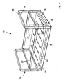
Figure 1 illustrates a perspective view of a preferred embodiment of a cage forming part of the transport system of the present invention; -
Figure 2 illustrates an alternative embodiment of the cage shown inFigure 1 , which cage is twice the height of the cage shown inFigure 1 ; -
Figure 3 illustrates a perspective view of part of a preferred embodiment of a trailer forming part of the transport system of the present invention, onto which trailer a plurality of the cages ofFigure 1 and2 may be loaded and secured for transport; and -
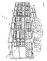
Figure 4 illustrates a perspective view of the trailer ofFig. 3 , which trailer is almost entirely filled with the cages ofFigs.1 and2 . - Referring now to the accompanying drawings, there is illustrated a transport system, generally indicated as 10, for particular use in loading, transporting and/or storing, in safety and with greater efficiency than was previously possible, large numbers of objects, in particular containers such as gas cylinders which, in the preferred embodiment illustrated, take the form of
conventional cylinders 44 andelongate cylinders 46. It will however be appreciated that thesystem 10 could be adapted for use with any number of other objects or containers (not shown). - The
system 10 consist primarily of a preferably mobile enclosure in the form of atrailer 12, in addition to a variety of cages, and in the preferred embodiment illustrated, aconventional cage 14 and anelongate cage 114, for use with theconventional cylinders 44 and theelongate cylinders 46 respectively. In use, a plurality of thecages trailer 12, as will be described in greater detail hereinafter. Theconventional cages 14 andelongate cages 114 are similar in configuration and operation, and thus like components have been accorded like reference numerals, and unless otherwise stated, perform a like function. The primary difference between theconventional cage 14 and theelongate cage 114 is the difference in height, theelongate cage 114 being approximately twice the height of theconventional cage 14 in order to be capable of housing theelongate cylinders 46. - Turning firstly to
Figure 1 , theconventional cage 14 comprises a pallet-like base 16 having four sides, a top surface and an underside, thebase 16 preferably being formed from box section aluminium, or any other suitable material. Extending from the extremity of thebase 16 is aframe 20, again preferably formed from aluminium or the like, theframe 20 extending above the tops of theconventional cylinders 44, the reason for which will be described in detail hereinafter. Theframe 20 again has four sides, corresponding to those of thebase 16. Theconventional cage 14 includes agate 22 removably secured thereto, whichgate 22, upon removal, facilitates ease of loading of theconventional cage 14 with theconventional cylinders 44. Once theconventional cage 14 has been filled with theconventional cylinders 44, thegate 22 is replaced and secured in place on theframe 20, in order to prevent theconventional cylinders 44 from falling from theconventional cage 14, in particular during transit. - The
base 16 includes at least one pair, and in the embodiment illustrated, two pairs, ofchannels 18 extending internally thereof. Thechannels 18 are shaped and dimensioned to receive the tines (not shown) of a forklift (not shown) or the like, in order to manoeuvre the filled (or empty)cages 14 onto or off thetrailer 12, as described in detail hereinafter. However, alternative means could be provided to facilitate lifting of thecage cage cage - The
frame 20 incorporates a pair ofopposed cross-beams 24 which are disposed just above the top of theconventional cylinders 44, such as to define a pair of upper edges of theframe 20. The pair ofcross-beams 24 therefore allow two ormore cages 14 to be stacked one on top of the other, in particular on thetrailer 12, although additionally at a depot (not shown) or similar storage facility. To further enhance the stacking capabilities of thecages 14, amale member 48 is formed integrally with the upper surface of eachcross beam 24, and in the preferred embodiment illustrated is triangular or V shaped in cross-section. The underside of eachbase 16 is therefore provided with a correspondingly shaped and located female member or recess (not shown), into which themale member 48 is engaged when onecage 14 is stacked on top of another. It will therefore be appreciated that the interlocking configuration of themale members 48 and the corresponding female members (not shown) provide increased stability to two ormore cages 14 stacked one on top of the other. This is particularly advantageous when transporting the filledcages 14 on thetrailer 12, but additionally if the filledcages 14 are stacked for storage at an outdoor depot or the like, and consequently exposed to high winds or minor collisions by forklifts or other vehicles or machinery. - It should be apparent that the positions of the
male members 48 and the female members (not shown) could be reversed, such that themale members 48 were provided on the underside of thebase 16, with each female member (not shown) being provided as a respective V-shaped channel or groove (not shown) formed in the upper surface of eachcross beam 24. It will also be apparent that themale members 48 and female members (not shown) could be of any suitable interlocking form. For example, eachmale member 48 could be in the form of one or more upstanding studs (not shown), cylindrical or otherwise, with the female member (not shown) then taking the form of a correspondingly shaped and dimensioned aperture (not shown) for receiving said stud. However, the use of the V-shaped cross section for both themale member 48 and the female member (not shown) allows for greater tolerances when aligning onecage 14 on top of anothercage 14 for stacking, as the V-shapedmale member 48 and female member (not shown) will tend to guide one another into the fully engaged position, in particular under the influence of gravity acting to force theupper cage 14 downwardly onto thelower cage 14, thereby facilitating the self alignment of thecages 14. - Referring now to
Figure 2 , theelongate cages 114 again include a pallet-like base 116, from the periphery of which extends aframe 120. The base incorporates two pairs ofchannels 118, and theframe 120 is provided with a releasablysecured gate 122 in order to facilitate the filling of thecage 114. It will be appreciated that thegate 122 could be omitted, with thecage 114 then being loaded from the open top thereof. - Each
frame 120 again includes a pair ofopposed cross-beams 124, atop each of which is located amale member 148. The comments made above with respect to the positioning and configuration of themale members 48 and corresponding female members (not shown) of theconventional cage 14 also apply to theelongate cage 114. - Referring now to
Figure 3 , thetrailer 12 consists of aplatform 26 having four sides, whichplatform 26, in the preferred embodiment illustrated, is the bed of thetrailer 12, extending upwardly from either side of which are a plurality ofuprights 32, preferably formed from box section steel or aluminium or any other suitable material. Thetrailer 12 further includes a pair of oppositely disposedupper rails 28 to which each of theuprights 32 are slidably mounted. Extending between the pair ofupper rails 28 are a plurality ofcross-members 34, increasing the structural integrity of thetrailer 12. It can therefore be seen that thetrailer 12 is cage-like in form, comprising theplatform 26 and the associated superstructure mounted thereon, which is of great importance, as it is illegal to transport gas canisters or containers such as theconventional cylinders 44 andelongate cylinders 46 in an enclosed load area, due to the dangers associated with an accumulation of explosive gas resulting from a leaking canister or canisters. It is for this reason that thecages cylinder system 10 is to be employed for the transport/storage of items or objects (not shown) which do not have such safety concerns, thecages - The
platform 26 of thetrailer 12 also preferrably includes retaining means in the form of a number of spaced apartdividers 36 which are arranged to receive the base 16,116 of the cages 14,114 therebetween, such as to prevent the cages 14,114 from sliding about on theplatform 26 during transit. The retaining means could however be of any suitable form. For example, the surface of theplatform 26 could be provided with a plurality of upstanding V shaped ridges (not shown) extending transversely across theplatform 26, having the same shape and configuration as themale members cages base cages - Formed integrally with the
platform 26, on either side thereof, is alower rail 30 to which each upright 32 is slidably secured. Eachupright 32 includes anupper coupling 38 which incorporates a conventional roller mechanism (not shown) which is slidably mounted to the respectiveupper rail 28, while each upright 32 further includes alower coupling 40 which again includes a conventional roller or other mechanism (not shown) which is slidably mounted to the respectivelower rail 30. Thus, it will be appreciated that each upright 32 may be displaced along the length of thetrailer 12 on the respectiveupper rail 28 andlower rail 30. Each upright 32 also includes a lockingmember 42 which is operable to lock theupright 32 relative to the respectiveupper rail 28 andlower rail 30. - Thus, in loading (or unloading) the
trailer 12, a forklift first picks up one of the cages 14,114 and approaches thetrailer 12 from the side or rear thereof. In approaching from the side of thetrailer 12, the cage 14,114 is first aligned with the space between any adjacent pair ofdividers 36, and anyuprights 32 which are located such as to prevent access to the interior of thetrailer 12 may be slid out of the way such as to permit the cage 14,114 to be deposited onto thetrailer 12. At this point a further cage 14,114 may then be stacked on top of the first cage 14,114, as shown clearly inFigure 3 . Once any given section of thetrailer 12 has been filled, the adjacent section is subsequently filled, and so on until theentire trailer 12 has been filled, or until all of the cages 14,114 required for transport have been deposited onto thetrailer 12, each time moving therespective uprights 32 to permit loading of the various sections via the side of thetrailer 12. - At this point, the
trailer 12 is ready for transport, and the plurality of cages 14,114 must therefore be secured in place in order to prevent them from becoming dislodged during transit. In order to secure the cages 14,114, asingle upright 32 is slid along between the respectiveupper rail 28 andlower rail 30 and positioned such as to overlie an outer corner of each pair of adjacent cages 14,114, as shown inFigure 4 . Theupright 32 is then secured in place by means of the lockingmember 42, as herein before described. This process is repeated until each upright 32 has been located in the correct position. Eachupright 32 is wide enough to extend a little way across theframe 20 of each of the adjacent cages 14,114. Thus, in transit, theuprights 32 prevent the adjacent cages 14,114 from falling off the side of thetrailer 12. When thetrailer 12 has reached its destination, the above process is reversed in order to permit the plurality of cages 14,114 to be unloaded therefrom.Additional uprights 32 could be provided for location, for example, at the midway point of eachcage cages trailer 12. - It is also envisaged that each upright 32 need not be secured to both the
upper rail 28 and thelower rail 30, and could be secured to one or the other. If this were the case, it would be necessary for the upright (not shown), and the connection between same and theupper rail 28 orlower rail 30, to be sufficiently reinforced to withstand the loading which could be applied thereto in the event of one or more of thecages trailer 12 at only one end of the upright, the upright would form a cantilever which, if loaded, would experience a significant bending moment, in addition to applying a significant torque to the connection between the upright and theupper rail 28 orlower rail 30. It is for this reason that, in the preferred embodiment illustrated, each upright 32 is secured to thetrailer 12 at both ends of theupright 32. - The present invention therefore provides a relatively simple yet versatile, safe and
robust transport system 10 for the transport/storage of, in particular,gas cylinders
Claims (14)
- A transport system (10) comprising at least one cage (14; 114) into which a plurality of objects (44; 46) may be loaded, the at least one cage (14; 114) being adapted to be lifted by suitable means; an enclosure (12) into which the at least one cage (14; 114) may be loaded for transport, the enclosure (12) comprising a platform (26) and at least one upright (32) moveable relative to the platform; characterised by retaining means (36) in operative association with the platform (26) and adapted to substantially reduce or present relative movement between the at least one cage (14; 114) and the platform (26)
- A system (10) according to claim 1 in which each cage (14; 114) comprises a base (16; 116) defining at least a pair of channels (18; 118) shaped and dimensioned for receiving a pair of tines of a forklift.
- A system (10) according to claim 2 in which each cage (14; 114) comprises a frame (20; 120) extending from the base (16; 116), at least one upper edge (24; 124) of the frame (20; 120) having one of a male (48; 148) or a female member, and a corresponding other of the male (48; 148) or female member is provided on an underside of the base (16; 116).
- A system (10) according to claim 3 in which each pair of male (48; 148) and female members are self aligning.
- A system (10) according to claim 3 or 4 in which the male (48; 148) and female members each have a substantially V shaped cross section.
- A system (10) according to any of claims 3 to 5 in which the frame (20; 120) may be opened outwardly on at least one side of the cage (14; 114).
- A system (10) according to any preceding claim in which the enclosure (12) comprises at least a pair of opposing uprights (32) independently moveable relative to the platform (26).
- A system (10) according to claim 6 in which the enclosure (12) comprises an upper rail (28) and a lower rail (30), each of which rails (28; 30) are disposed substantially parallel to the platform (26), the or each upright (32) being slidably mounted to the upper rail (28) and the lower rail (30).
- A system (10) according to claim 7 in which the enclosure (12) comprises a pair of opposed upper rails (28) and a pair of opposed lower rails (30).
- A system (10) according to claim 8 or 9 in which the or each lower rail (30) is formed integrally with the platform (26).
- A system (10) according to any preceding claim in which the or each upright (3 2) may be locked in position relative to the platform (26).
- A system (10) according to any preceding claim in which the retaining means (36) comprises at least a pair of dividers (36) projecting upwardly from the platform (26).
- A system (10) according to any preceding claim in which the enclosure (12) is mobile.
- A system (10) according to any preceding claim in which the enclosure (12) is a vehicular trailer (12).
Applications Claiming Priority (2)
| Application Number | Priority Date | Filing Date | Title |
|---|---|---|---|
| GB0404983A GB0404983D0 (en) | 2004-03-05 | 2004-03-05 | A transport system |
| GB0404983 | 2004-03-05 |
Publications (3)
| Publication Number | Publication Date |
|---|---|
| EP1571096A2 EP1571096A2 (en) | 2005-09-07 |
| EP1571096A3 EP1571096A3 (en) | 2005-12-14 |
| EP1571096B1 true EP1571096B1 (en) | 2013-11-13 |
Family
ID=32088774
Family Applications (1)
| Application Number | Title | Priority Date | Filing Date |
|---|---|---|---|
| EP20050075494 Active EP1571096B1 (en) | 2004-03-05 | 2005-03-04 | A transport system |
Country Status (2)
| Country | Link |
|---|---|
| EP (1) | EP1571096B1 (en) |
| GB (1) | GB0404983D0 (en) |
Cited By (1)
| Publication number | Priority date | Publication date | Assignee | Title |
|---|---|---|---|---|
| EP3557116A1 (en) * | 2018-04-20 | 2019-10-23 | Linde Aktiengesellschaft | Transportation module for transporting a plurality of gas cylinders |
Families Citing this family (4)
| Publication number | Priority date | Publication date | Assignee | Title |
|---|---|---|---|---|
| WO2011003414A1 (en) * | 2009-07-07 | 2011-01-13 | Jens-Christian Herold | A logistic container, such as a shipping container, and a method for loading and unloading it |
| FR2978428B1 (en) * | 2011-07-29 | 2014-10-17 | Air Flow | SYSTEM FOR TRANSPORTING PRESSURIZED FLUID BOTTLES |
| WO2015081373A1 (en) * | 2013-12-04 | 2015-06-11 | Noske Anthony | Transport container |
| CN104743297B (en) * | 2013-12-25 | 2017-08-08 | 南通中集特种运输设备制造有限公司 | Gas cylinder case |
Family Cites Families (5)
| Publication number | Priority date | Publication date | Assignee | Title |
|---|---|---|---|---|
| AT288253B (en) * | 1968-07-15 | 1971-02-25 | Talbot Waggonfab | Containers for optional transport on rail, road or water vehicles |
| FR2075836A1 (en) * | 1969-12-12 | 1971-10-15 | Avit Paul | |
| FR2732668B1 (en) * | 1995-04-06 | 1997-06-13 | Ind De Thermoformage Et Mecano | CONTAINER, ESPECIALLY A PALLET-SHAPED BASE TYPE |
| GB2353277B (en) * | 1999-08-16 | 2003-09-17 | Sea Containers Services Ltd | Freight container |
| AU2002360864B2 (en) * | 2001-11-30 | 2009-03-05 | Almar Packaging International Inc. | Intermediate bulk container |
-
2004
- 2004-03-05 GB GB0404983A patent/GB0404983D0/en not_active Ceased
-
2005
- 2005-03-04 EP EP20050075494 patent/EP1571096B1/en active Active
Cited By (1)
| Publication number | Priority date | Publication date | Assignee | Title |
|---|---|---|---|---|
| EP3557116A1 (en) * | 2018-04-20 | 2019-10-23 | Linde Aktiengesellschaft | Transportation module for transporting a plurality of gas cylinders |
Also Published As
| Publication number | Publication date |
|---|---|
| EP1571096A2 (en) | 2005-09-07 |
| EP1571096A3 (en) | 2005-12-14 |
| GB0404983D0 (en) | 2004-04-07 |
Similar Documents
| Publication | Publication Date | Title |
|---|---|---|
| EP3065595B1 (en) | A container roll out warehousing system, method of storing cargo | |
| US9868589B2 (en) | Modular transportation systems, devices and methods | |
| US8529175B2 (en) | Method for transporting concentrated mass loads by container | |
| US9580236B1 (en) | Storage and transport container | |
| US10632894B2 (en) | Two-level pallet for stackable loading | |
| US20120288349A1 (en) | Container Handling Device, Use of Such a One, and Methods in Unloading and Loading | |
| US3993343A (en) | Transporting system | |
| EP1571096B1 (en) | A transport system | |
| US20220234817A1 (en) | Vehicle Stacking Crate | |
| GB2353277A (en) | Freight container with a movable support strut | |
| US4618068A (en) | Method and apparatus for shipping and storing cargo | |
| WO1999014137A1 (en) | Platforms for transporting cargo | |
| US8950988B2 (en) | Method and apparatus for stacking loads in vehicles | |
| US3934926A (en) | Transporting system | |
| US8689991B2 (en) | Transport container | |
| WO2011003414A1 (en) | A logistic container, such as a shipping container, and a method for loading and unloading it | |
| US9908723B2 (en) | Modular transportation systems, devices and methods | |
| JP3999925B2 (en) | Metal material transport container with stacked structure | |
| EP3494071B1 (en) | Collapsible container, method of folding a container, method of unfolding a container | |
| CA1057124A (en) | Transporting system | |
| CA1065680A (en) | Transporting system |
Legal Events
| Date | Code | Title | Description |
|---|---|---|---|
| PUAI | Public reference made under article 153(3) epc to a published international application that has entered the european phase |
Free format text: ORIGINAL CODE: 0009012 |
|
| AK | Designated contracting states |
Kind code of ref document: A2 Designated state(s): AT BE BG CH CY CZ DE DK EE ES FI FR GB GR HU IE IS IT LI LT LU MC NL PL PT RO SE SI SK TR |
|
| AX | Request for extension of the european patent |
Extension state: AL BA HR LV MK YU |
|
| PUAL | Search report despatched |
Free format text: ORIGINAL CODE: 0009013 |
|
| AK | Designated contracting states |
Kind code of ref document: A3 Designated state(s): AT BE BG CH CY CZ DE DK EE ES FI FR GB GR HU IE IS IT LI LT LU MC NL PL PT RO SE SI SK TR |
|
| AX | Request for extension of the european patent |
Extension state: AL BA HR LV MK YU |
|
| 17P | Request for examination filed |
Effective date: 20060614 |
|
| AKX | Designation fees paid |
Designated state(s): AT BE BG CH CY CZ DE DK EE ES FI FR GB GR HU IE IS IT LI LT LU MC NL PL PT RO SE SI SK TR |
|
| 17Q | First examination report despatched |
Effective date: 20070403 |
|
| GRAP | Despatch of communication of intention to grant a patent |
Free format text: ORIGINAL CODE: EPIDOSNIGR1 |
|
| GRAS | Grant fee paid |
Free format text: ORIGINAL CODE: EPIDOSNIGR3 |
|
| GRAL | Information related to payment of fee for publishing/printing deleted |
Free format text: ORIGINAL CODE: EPIDOSDIGR3 |
|
| GRAS | Grant fee paid |
Free format text: ORIGINAL CODE: EPIDOSNIGR3 |
|
| GRAF | Information related to payment of grant fee modified |
Free format text: ORIGINAL CODE: EPIDOSCIGR3 |
|
| GRAA | (expected) grant |
Free format text: ORIGINAL CODE: 0009210 |
|
| RAP1 | Party data changed (applicant data changed or rights of an application transferred) |
Owner name: MALACHY, HUGHES |
|
| RIN1 | Information on inventor provided before grant (corrected) |
Inventor name: MALACHY, HUGHES |
|
| AK | Designated contracting states |
Kind code of ref document: B1 Designated state(s): AT BE BG CH CY CZ DE DK EE ES FI FR GB GR HU IE IS IT LI LT LU MC NL PL PT RO SE SI SK TR |
|
| REG | Reference to a national code |
Ref country code: GB Ref legal event code: FG4D |
|
| REG | Reference to a national code |
Ref country code: CH Ref legal event code: EP |
|
| REG | Reference to a national code |
Ref country code: AT Ref legal event code: REF Ref document number: 640470 Country of ref document: AT Kind code of ref document: T Effective date: 20131215 |
|
| REG | Reference to a national code |
Ref country code: IE Ref legal event code: FG4D |
|
| REG | Reference to a national code |
Ref country code: DE Ref legal event code: R096 Ref document number: 602005041836 Country of ref document: DE Effective date: 20140109 |
|
| REG | Reference to a national code |
Ref country code: NL Ref legal event code: VDEP Effective date: 20131113 |
|
| REG | Reference to a national code |
Ref country code: AT Ref legal event code: MK05 Ref document number: 640470 Country of ref document: AT Kind code of ref document: T Effective date: 20131113 |
|
| REG | Reference to a national code |
Ref country code: LT Ref legal event code: MG4D |
|
| PG25 | Lapsed in a contracting state [announced via postgrant information from national office to epo] |
Ref country code: FI Free format text: LAPSE BECAUSE OF FAILURE TO SUBMIT A TRANSLATION OF THE DESCRIPTION OR TO PAY THE FEE WITHIN THE PRESCRIBED TIME-LIMIT Effective date: 20131113 Ref country code: IS Free format text: LAPSE BECAUSE OF FAILURE TO SUBMIT A TRANSLATION OF THE DESCRIPTION OR TO PAY THE FEE WITHIN THE PRESCRIBED TIME-LIMIT Effective date: 20140313 Ref country code: LT Free format text: LAPSE BECAUSE OF FAILURE TO SUBMIT A TRANSLATION OF THE DESCRIPTION OR TO PAY THE FEE WITHIN THE PRESCRIBED TIME-LIMIT Effective date: 20131113 Ref country code: SE Free format text: LAPSE BECAUSE OF FAILURE TO SUBMIT A TRANSLATION OF THE DESCRIPTION OR TO PAY THE FEE WITHIN THE PRESCRIBED TIME-LIMIT Effective date: 20131113 Ref country code: NL Free format text: LAPSE BECAUSE OF FAILURE TO SUBMIT A TRANSLATION OF THE DESCRIPTION OR TO PAY THE FEE WITHIN THE PRESCRIBED TIME-LIMIT Effective date: 20131113 |
|
| PG25 | Lapsed in a contracting state [announced via postgrant information from national office to epo] |
Ref country code: ES Free format text: LAPSE BECAUSE OF FAILURE TO SUBMIT A TRANSLATION OF THE DESCRIPTION OR TO PAY THE FEE WITHIN THE PRESCRIBED TIME-LIMIT Effective date: 20131113 Ref country code: BE Free format text: LAPSE BECAUSE OF FAILURE TO SUBMIT A TRANSLATION OF THE DESCRIPTION OR TO PAY THE FEE WITHIN THE PRESCRIBED TIME-LIMIT Effective date: 20131113 Ref country code: CY Free format text: LAPSE BECAUSE OF FAILURE TO SUBMIT A TRANSLATION OF THE DESCRIPTION OR TO PAY THE FEE WITHIN THE PRESCRIBED TIME-LIMIT Effective date: 20131113 Ref country code: AT Free format text: LAPSE BECAUSE OF FAILURE TO SUBMIT A TRANSLATION OF THE DESCRIPTION OR TO PAY THE FEE WITHIN THE PRESCRIBED TIME-LIMIT Effective date: 20131113 |
|
| PG25 | Lapsed in a contracting state [announced via postgrant information from national office to epo] |
Ref country code: PT Free format text: LAPSE BECAUSE OF FAILURE TO SUBMIT A TRANSLATION OF THE DESCRIPTION OR TO PAY THE FEE WITHIN THE PRESCRIBED TIME-LIMIT Effective date: 20140313 |
|
| PG25 | Lapsed in a contracting state [announced via postgrant information from national office to epo] |
Ref country code: EE Free format text: LAPSE BECAUSE OF FAILURE TO SUBMIT A TRANSLATION OF THE DESCRIPTION OR TO PAY THE FEE WITHIN THE PRESCRIBED TIME-LIMIT Effective date: 20131113 |
|
| REG | Reference to a national code |
Ref country code: DE Ref legal event code: R097 Ref document number: 602005041836 Country of ref document: DE |
|
| PG25 | Lapsed in a contracting state [announced via postgrant information from national office to epo] |
Ref country code: CZ Free format text: LAPSE BECAUSE OF FAILURE TO SUBMIT A TRANSLATION OF THE DESCRIPTION OR TO PAY THE FEE WITHIN THE PRESCRIBED TIME-LIMIT Effective date: 20131113 Ref country code: PL Free format text: LAPSE BECAUSE OF FAILURE TO SUBMIT A TRANSLATION OF THE DESCRIPTION OR TO PAY THE FEE WITHIN THE PRESCRIBED TIME-LIMIT Effective date: 20131113 Ref country code: SK Free format text: LAPSE BECAUSE OF FAILURE TO SUBMIT A TRANSLATION OF THE DESCRIPTION OR TO PAY THE FEE WITHIN THE PRESCRIBED TIME-LIMIT Effective date: 20131113 Ref country code: RO Free format text: LAPSE BECAUSE OF FAILURE TO SUBMIT A TRANSLATION OF THE DESCRIPTION OR TO PAY THE FEE WITHIN THE PRESCRIBED TIME-LIMIT Effective date: 20131113 |
|
| PLBE | No opposition filed within time limit |
Free format text: ORIGINAL CODE: 0009261 |
|
| STAA | Information on the status of an ep patent application or granted ep patent |
Free format text: STATUS: NO OPPOSITION FILED WITHIN TIME LIMIT |
|
| PG25 | Lapsed in a contracting state [announced via postgrant information from national office to epo] |
Ref country code: DK Free format text: LAPSE BECAUSE OF FAILURE TO SUBMIT A TRANSLATION OF THE DESCRIPTION OR TO PAY THE FEE WITHIN THE PRESCRIBED TIME-LIMIT Effective date: 20131113 |
|
| REG | Reference to a national code |
Ref country code: DE Ref legal event code: R119 Ref document number: 602005041836 Country of ref document: DE |
|
| 26N | No opposition filed |
Effective date: 20140814 |
|
| PG25 | Lapsed in a contracting state [announced via postgrant information from national office to epo] |
Ref country code: LU Free format text: LAPSE BECAUSE OF FAILURE TO SUBMIT A TRANSLATION OF THE DESCRIPTION OR TO PAY THE FEE WITHIN THE PRESCRIBED TIME-LIMIT Effective date: 20140304 |
|
| REG | Reference to a national code |
Ref country code: CH Ref legal event code: PL |
|
| REG | Reference to a national code |
Ref country code: DE Ref legal event code: R097 Ref document number: 602005041836 Country of ref document: DE Effective date: 20140814 |
|
| REG | Reference to a national code |
Ref country code: FR Ref legal event code: ST Effective date: 20141128 |
|
| REG | Reference to a national code |
Ref country code: DE Ref legal event code: R119 Ref document number: 602005041836 Country of ref document: DE Effective date: 20141001 |
|
| PG25 | Lapsed in a contracting state [announced via postgrant information from national office to epo] |
Ref country code: FR Free format text: LAPSE BECAUSE OF NON-PAYMENT OF DUE FEES Effective date: 20140331 Ref country code: LI Free format text: LAPSE BECAUSE OF NON-PAYMENT OF DUE FEES Effective date: 20140331 Ref country code: CH Free format text: LAPSE BECAUSE OF NON-PAYMENT OF DUE FEES Effective date: 20140331 Ref country code: DE Free format text: LAPSE BECAUSE OF NON-PAYMENT OF DUE FEES Effective date: 20141001 |
|
| PG25 | Lapsed in a contracting state [announced via postgrant information from national office to epo] |
Ref country code: SI Free format text: LAPSE BECAUSE OF FAILURE TO SUBMIT A TRANSLATION OF THE DESCRIPTION OR TO PAY THE FEE WITHIN THE PRESCRIBED TIME-LIMIT Effective date: 20131113 |
|
| PG25 | Lapsed in a contracting state [announced via postgrant information from national office to epo] |
Ref country code: IT Free format text: LAPSE BECAUSE OF FAILURE TO SUBMIT A TRANSLATION OF THE DESCRIPTION OR TO PAY THE FEE WITHIN THE PRESCRIBED TIME-LIMIT Effective date: 20131113 |
|
| PG25 | Lapsed in a contracting state [announced via postgrant information from national office to epo] |
Ref country code: BG Free format text: LAPSE BECAUSE OF FAILURE TO SUBMIT A TRANSLATION OF THE DESCRIPTION OR TO PAY THE FEE WITHIN THE PRESCRIBED TIME-LIMIT Effective date: 20131113 Ref country code: MC Free format text: LAPSE BECAUSE OF FAILURE TO SUBMIT A TRANSLATION OF THE DESCRIPTION OR TO PAY THE FEE WITHIN THE PRESCRIBED TIME-LIMIT Effective date: 20131113 |
|
| PG25 | Lapsed in a contracting state [announced via postgrant information from national office to epo] |
Ref country code: GR Free format text: LAPSE BECAUSE OF FAILURE TO SUBMIT A TRANSLATION OF THE DESCRIPTION OR TO PAY THE FEE WITHIN THE PRESCRIBED TIME-LIMIT Effective date: 20140214 |
|
| PG25 | Lapsed in a contracting state [announced via postgrant information from national office to epo] |
Ref country code: TR Free format text: LAPSE BECAUSE OF FAILURE TO SUBMIT A TRANSLATION OF THE DESCRIPTION OR TO PAY THE FEE WITHIN THE PRESCRIBED TIME-LIMIT Effective date: 20131113 Ref country code: HU Free format text: LAPSE BECAUSE OF FAILURE TO SUBMIT A TRANSLATION OF THE DESCRIPTION OR TO PAY THE FEE WITHIN THE PRESCRIBED TIME-LIMIT; INVALID AB INITIO Effective date: 20050304 |
|
| PGFP | Annual fee paid to national office [announced via postgrant information from national office to epo] |
Ref country code: IE Payment date: 20240607 Year of fee payment: 20 |
|
| PGFP | Annual fee paid to national office [announced via postgrant information from national office to epo] |
Ref country code: GB Payment date: 20240611 Year of fee payment: 20 |