EP0319956A1 - Valve operating mechanism - Google Patents
Valve operating mechanism Download PDFInfo
- Publication number
- EP0319956A1 EP0319956A1 EP88120459A EP88120459A EP0319956A1 EP 0319956 A1 EP0319956 A1 EP 0319956A1 EP 88120459 A EP88120459 A EP 88120459A EP 88120459 A EP88120459 A EP 88120459A EP 0319956 A1 EP0319956 A1 EP 0319956A1
- Authority
- EP
- European Patent Office
- Prior art keywords
- valve
- exhaust
- engine
- exhaust valves
- operating mechanism
- Prior art date
- Legal status (The legal status is an assumption and is not a legal conclusion. Google has not performed a legal analysis and makes no representation as to the accuracy of the status listed.)
- Granted
Links
Images




Classifications
-
- F—MECHANICAL ENGINEERING; LIGHTING; HEATING; WEAPONS; BLASTING
- F02—COMBUSTION ENGINES; HOT-GAS OR COMBUSTION-PRODUCT ENGINE PLANTS
- F02D—CONTROLLING COMBUSTION ENGINES
- F02D13/00—Controlling the engine output power by varying inlet or exhaust valve operating characteristics, e.g. timing
- F02D13/02—Controlling the engine output power by varying inlet or exhaust valve operating characteristics, e.g. timing during engine operation
- F02D13/0203—Variable control of intake and exhaust valves
- F02D13/0215—Variable control of intake and exhaust valves changing the valve timing only
- F02D13/0219—Variable control of intake and exhaust valves changing the valve timing only by shifting the phase, i.e. the opening periods of the valves are constant
-
- F—MECHANICAL ENGINEERING; LIGHTING; HEATING; WEAPONS; BLASTING
- F01—MACHINES OR ENGINES IN GENERAL; ENGINE PLANTS IN GENERAL; STEAM ENGINES
- F01L—CYCLICALLY OPERATING VALVES FOR MACHINES OR ENGINES
- F01L1/00—Valve-gear or valve arrangements, e.g. lift-valve gear
-
- F—MECHANICAL ENGINEERING; LIGHTING; HEATING; WEAPONS; BLASTING
- F01—MACHINES OR ENGINES IN GENERAL; ENGINE PLANTS IN GENERAL; STEAM ENGINES
- F01L—CYCLICALLY OPERATING VALVES FOR MACHINES OR ENGINES
- F01L1/00—Valve-gear or valve arrangements, e.g. lift-valve gear
- F01L1/12—Transmitting gear between valve drive and valve
- F01L1/18—Rocking arms or levers
- F01L1/185—Overhead end-pivot rocking arms
-
- F—MECHANICAL ENGINEERING; LIGHTING; HEATING; WEAPONS; BLASTING
- F01—MACHINES OR ENGINES IN GENERAL; ENGINE PLANTS IN GENERAL; STEAM ENGINES
- F01L—CYCLICALLY OPERATING VALVES FOR MACHINES OR ENGINES
- F01L1/00—Valve-gear or valve arrangements, e.g. lift-valve gear
- F01L1/26—Valve-gear or valve arrangements, e.g. lift-valve gear characterised by the provision of two or more valves operated simultaneously by same transmitting-gear; peculiar to machines or engines with more than two lift-valves per cylinder
-
- F—MECHANICAL ENGINEERING; LIGHTING; HEATING; WEAPONS; BLASTING
- F01—MACHINES OR ENGINES IN GENERAL; ENGINE PLANTS IN GENERAL; STEAM ENGINES
- F01L—CYCLICALLY OPERATING VALVES FOR MACHINES OR ENGINES
- F01L13/00—Modifications of valve-gear to facilitate reversing, braking, starting, changing compression ratio, or other specific operations
- F01L13/0015—Modifications of valve-gear to facilitate reversing, braking, starting, changing compression ratio, or other specific operations for optimising engine performances by modifying valve lift according to various working parameters, e.g. rotational speed, load, torque
-
- F—MECHANICAL ENGINEERING; LIGHTING; HEATING; WEAPONS; BLASTING
- F01—MACHINES OR ENGINES IN GENERAL; ENGINE PLANTS IN GENERAL; STEAM ENGINES
- F01L—CYCLICALLY OPERATING VALVES FOR MACHINES OR ENGINES
- F01L13/00—Modifications of valve-gear to facilitate reversing, braking, starting, changing compression ratio, or other specific operations
- F01L13/0015—Modifications of valve-gear to facilitate reversing, braking, starting, changing compression ratio, or other specific operations for optimising engine performances by modifying valve lift according to various working parameters, e.g. rotational speed, load, torque
- F01L13/0021—Modifications of valve-gear to facilitate reversing, braking, starting, changing compression ratio, or other specific operations for optimising engine performances by modifying valve lift according to various working parameters, e.g. rotational speed, load, torque by modification of rocker arm ratio
- F01L13/0026—Modifications of valve-gear to facilitate reversing, braking, starting, changing compression ratio, or other specific operations for optimising engine performances by modifying valve lift according to various working parameters, e.g. rotational speed, load, torque by modification of rocker arm ratio by means of an eccentric
-
- F—MECHANICAL ENGINEERING; LIGHTING; HEATING; WEAPONS; BLASTING
- F02—COMBUSTION ENGINES; HOT-GAS OR COMBUSTION-PRODUCT ENGINE PLANTS
- F02B—INTERNAL-COMBUSTION PISTON ENGINES; COMBUSTION ENGINES IN GENERAL
- F02B29/00—Engines characterised by provision for charging or scavenging not provided for in groups F02B25/00, F02B27/00 or F02B33/00 - F02B39/00; Details thereof
- F02B29/08—Modifying distribution valve timing for charging purposes
-
- F—MECHANICAL ENGINEERING; LIGHTING; HEATING; WEAPONS; BLASTING
- F02—COMBUSTION ENGINES; HOT-GAS OR COMBUSTION-PRODUCT ENGINE PLANTS
- F02B—INTERNAL-COMBUSTION PISTON ENGINES; COMBUSTION ENGINES IN GENERAL
- F02B37/00—Engines characterised by provision of pumps driven at least for part of the time by exhaust
- F02B37/02—Gas passages between engine outlet and pump drive, e.g. reservoirs
-
- F—MECHANICAL ENGINEERING; LIGHTING; HEATING; WEAPONS; BLASTING
- F02—COMBUSTION ENGINES; HOT-GAS OR COMBUSTION-PRODUCT ENGINE PLANTS
- F02D—CONTROLLING COMBUSTION ENGINES
- F02D13/00—Controlling the engine output power by varying inlet or exhaust valve operating characteristics, e.g. timing
- F02D13/02—Controlling the engine output power by varying inlet or exhaust valve operating characteristics, e.g. timing during engine operation
- F02D13/0242—Variable control of the exhaust valves only
- F02D13/0246—Variable control of the exhaust valves only changing valve lift or valve lift and timing
-
- F—MECHANICAL ENGINEERING; LIGHTING; HEATING; WEAPONS; BLASTING
- F02—COMBUSTION ENGINES; HOT-GAS OR COMBUSTION-PRODUCT ENGINE PLANTS
- F02D—CONTROLLING COMBUSTION ENGINES
- F02D13/00—Controlling the engine output power by varying inlet or exhaust valve operating characteristics, e.g. timing
- F02D13/02—Controlling the engine output power by varying inlet or exhaust valve operating characteristics, e.g. timing during engine operation
- F02D13/0242—Variable control of the exhaust valves only
- F02D13/0249—Variable control of the exhaust valves only changing the valve timing only
-
- F—MECHANICAL ENGINEERING; LIGHTING; HEATING; WEAPONS; BLASTING
- F02—COMBUSTION ENGINES; HOT-GAS OR COMBUSTION-PRODUCT ENGINE PLANTS
- F02D—CONTROLLING COMBUSTION ENGINES
- F02D13/00—Controlling the engine output power by varying inlet or exhaust valve operating characteristics, e.g. timing
- F02D13/02—Controlling the engine output power by varying inlet or exhaust valve operating characteristics, e.g. timing during engine operation
- F02D13/0257—Independent control of two or more intake or exhaust valves respectively, i.e. one of two intake valves remains closed or is opened partially while the other is fully opened
-
- F—MECHANICAL ENGINEERING; LIGHTING; HEATING; WEAPONS; BLASTING
- F02—COMBUSTION ENGINES; HOT-GAS OR COMBUSTION-PRODUCT ENGINE PLANTS
- F02D—CONTROLLING COMBUSTION ENGINES
- F02D13/00—Controlling the engine output power by varying inlet or exhaust valve operating characteristics, e.g. timing
- F02D13/02—Controlling the engine output power by varying inlet or exhaust valve operating characteristics, e.g. timing during engine operation
- F02D13/0261—Controlling the valve overlap
-
- F—MECHANICAL ENGINEERING; LIGHTING; HEATING; WEAPONS; BLASTING
- F01—MACHINES OR ENGINES IN GENERAL; ENGINE PLANTS IN GENERAL; STEAM ENGINES
- F01L—CYCLICALLY OPERATING VALVES FOR MACHINES OR ENGINES
- F01L1/00—Valve-gear or valve arrangements, e.g. lift-valve gear
- F01L1/12—Transmitting gear between valve drive and valve
- F01L1/18—Rocking arms or levers
- F01L2001/188—Fulcrums at upper surface
-
- F—MECHANICAL ENGINEERING; LIGHTING; HEATING; WEAPONS; BLASTING
- F01—MACHINES OR ENGINES IN GENERAL; ENGINE PLANTS IN GENERAL; STEAM ENGINES
- F01L—CYCLICALLY OPERATING VALVES FOR MACHINES OR ENGINES
- F01L2800/00—Methods of operation using a variable valve timing mechanism
- F01L2800/06—Timing or lift different for valves of same cylinder
-
- F—MECHANICAL ENGINEERING; LIGHTING; HEATING; WEAPONS; BLASTING
- F01—MACHINES OR ENGINES IN GENERAL; ENGINE PLANTS IN GENERAL; STEAM ENGINES
- F01L—CYCLICALLY OPERATING VALVES FOR MACHINES OR ENGINES
- F01L2820/00—Details on specific features characterising valve gear arrangements
- F01L2820/03—Auxiliary actuators
- F01L2820/032—Electric motors
-
- F—MECHANICAL ENGINEERING; LIGHTING; HEATING; WEAPONS; BLASTING
- F02—COMBUSTION ENGINES; HOT-GAS OR COMBUSTION-PRODUCT ENGINE PLANTS
- F02B—INTERNAL-COMBUSTION PISTON ENGINES; COMBUSTION ENGINES IN GENERAL
- F02B2275/00—Other engines, components or details, not provided for in other groups of this subclass
- F02B2275/18—DOHC [Double overhead camshaft]
-
- F—MECHANICAL ENGINEERING; LIGHTING; HEATING; WEAPONS; BLASTING
- F02—COMBUSTION ENGINES; HOT-GAS OR COMBUSTION-PRODUCT ENGINE PLANTS
- F02D—CONTROLLING COMBUSTION ENGINES
- F02D13/00—Controlling the engine output power by varying inlet or exhaust valve operating characteristics, e.g. timing
- F02D13/02—Controlling the engine output power by varying inlet or exhaust valve operating characteristics, e.g. timing during engine operation
- F02D2013/0296—Changing the valve lift only
-
- F—MECHANICAL ENGINEERING; LIGHTING; HEATING; WEAPONS; BLASTING
- F02—COMBUSTION ENGINES; HOT-GAS OR COMBUSTION-PRODUCT ENGINE PLANTS
- F02F—CYLINDERS, PISTONS OR CASINGS, FOR COMBUSTION ENGINES; ARRANGEMENTS OF SEALINGS IN COMBUSTION ENGINES
- F02F1/00—Cylinders; Cylinder heads
- F02F1/24—Cylinder heads
- F02F1/42—Shape or arrangement of intake or exhaust channels in cylinder heads
- F02F1/4214—Shape or arrangement of intake or exhaust channels in cylinder heads specially adapted for four or more valves per cylinder
-
- F—MECHANICAL ENGINEERING; LIGHTING; HEATING; WEAPONS; BLASTING
- F02—COMBUSTION ENGINES; HOT-GAS OR COMBUSTION-PRODUCT ENGINE PLANTS
- F02F—CYLINDERS, PISTONS OR CASINGS, FOR COMBUSTION ENGINES; ARRANGEMENTS OF SEALINGS IN COMBUSTION ENGINES
- F02F1/00—Cylinders; Cylinder heads
- F02F1/24—Cylinder heads
- F02F2001/244—Arrangement of valve stems in cylinder heads
- F02F2001/245—Arrangement of valve stems in cylinder heads the valve stems being orientated at an angle with the cylinder axis
-
- Y—GENERAL TAGGING OF NEW TECHNOLOGICAL DEVELOPMENTS; GENERAL TAGGING OF CROSS-SECTIONAL TECHNOLOGIES SPANNING OVER SEVERAL SECTIONS OF THE IPC; TECHNICAL SUBJECTS COVERED BY FORMER USPC CROSS-REFERENCE ART COLLECTIONS [XRACs] AND DIGESTS
- Y02—TECHNOLOGIES OR APPLICATIONS FOR MITIGATION OR ADAPTATION AGAINST CLIMATE CHANGE
- Y02T—CLIMATE CHANGE MITIGATION TECHNOLOGIES RELATED TO TRANSPORTATION
- Y02T10/00—Road transport of goods or passengers
- Y02T10/10—Internal combustion engine [ICE] based vehicles
- Y02T10/12—Improving ICE efficiencies
Definitions
- the present invention relates to a valve operating mechanism for an internal combustion engine having a plurality of exhaust valves per cylinder.
- a prior art valve operating mechanism of the above described kind is adapted to operate two exhaust valves and two intake valves of a four-stroke cycle four-valves-per-cylinder internal combustion engine at the valve timings as shown in Fig. 7.
- valve timings E1 and E2 of the two exhaust valves and the valve timings I1 and I2 of the two intake valves respectively have such predetermined phase differences that at the positions of the piston adjacent the top dead center in the transition from the exhaust stroke to the intake stroke a set of one exhaust valve and one intake valve are closed and a set of the other exhaust valve and the other intake valve are opened with a view to increaing the velocity of flow of the fresh intake mixture within the cylinder and thereby improving the scavenging efficiency. Further, at the position of the piston adjacent the bottom dead center in the transition from the intake stroke to the compression stroke, only one of the intake valves is opened to cause a swirl of the intake mixture for thereby improving the combustibility during high-speed high-load operation of the engine.
- a novel valve operating mechanism for an internal combustion engine having a plurality of exhaust valves per cylinder.
- the valve operating mechanism comprises means for driving the exhaust valves at such a valve timing that makes opening of the exhaust valves cause blowdown pressures with a phase difference.
- This structure is effective for solving the above noted problems inherent in the prior art device.
- the curves E1 and E2 and the curve I depict valve timings for a four-stroke cycle four-valves-per-cylinder internal combustion engine according to an embodiment of the present invention.
- the curves E1 and E2 represent the valve timings of exhaust valves 1 and 2, respectively.
- the exhaust valves 1 and 2 start opening in advance of the bottom dead center (BDC) after which the exhaust stroke begins and with a phase difference ⁇ .
- the exhaust valves 1 and 2 then reach the maximum lift points in the middle of the exhaust stroke, respectively and fully close synchronously with each other in retard of the top dead center (TDC) after which the intake stroke begins. Closing movements of the exhaust valves 1 and 2 are synchronous with each other, i.e., performed at the same speed.
- the curve "I" represents a valve timing common to intake valves 3 and 4.
- the intake valves 3 and 4 start opening in advance of the top dead center, reach a maximum lift point in the middle of the exhaust stroke and fully close in retard of the bottom dead center after which the compression stroke begins. With those valve timings, the exhaust valves 1 and 2 and intake valves 3 and 4 are given a predetermined valve overlapping angle about the top dead center.
- Fig. 2 shows a camshaft 5 for the exhaust valves 1 and 2.
- the camshaft 5 has cams 6 and 7 which are so profiled as to have a phase difference of ⁇ /2 at the opening valve points and a phase difference of 0 (zero) at the closing valve points.
- the dotted line curve indicates the pressure wave occurring in the exhaust passages downstream of the exhaust valves 1 and 2.
- the pressure wave results from the composition of a blowdown pressure (indicated by the one-dot-chain line curve) produced by the opening of the exhaust valve 1 and a blowdown pressure (indicated by the two-dot-chain line curve) produced by the opening of the exhaust valve 2. Therefore, the vibration amplitude of the pressure wave in the embodiment of this invention can be smaller than that (indicated by the solid line curve) in the prior art device of which exhaust valves open at the same time, i.e., with the same phase.
- Fig. 4 shows by the dotted line curve the pressure variations of the pressure wave measured under the condition that the engine is operated at the speed of 3600 rpm so that the pressure wave becomes positive in the place spaced by 120 mm downstream of the exhaust valves 1 and 2 upon closure of the exhaust valves 1 and 2.
- the solid line curve represents the pressure variations of the pressure wave in the comprable prior art device in which the exhaust valves open with the same phase. From this test result, it will be understood that according to the present invention the variation amplitude of the reflected wave (the portion indicated by "B”) can be made smaller by the amount corresponding to the amount by which the blowdown (the portion indicated by "A”) is reduced.
- Fig. 5 shows, with respect to the embodiment of this invention and the prior art device, how the engine output torque and volumetric efficiency vary with variation of the engine rpm. From this graph, it will be understood that while in case of the prior art device there occurs a considerable drop or fall of the output toruqe and volumetric efficiency at or near the engine speed of 3600 rpm, a corresponding drop is smaller in case of this embodiment.
- the drop of the output torque is caused by the closure of the exhaust valves 1 and 2 at or near the engine speed of 3600 rpm which, as having been described above, causes a positive pressure on the downstream side of the exhaust valves 1 and 2.
- the downblow pressures are produced with a predetermined phase difference, i.e., at the different timings relative to the crank angle by the opening of the exhaust valves 1 and 2, thus making smaller the vibration amplitude of the pressure wave occurring in the exhaust passage, reducing the pumping loss caused by the consumption of the engine output for discharging the exhaust gases, reducing the residual gases whilst increasing the volumetric efficiency of the intake mixture and making it possible to prevent a drop of an output torque during middle speed operation of the engine.
- Fig. 6 shows another embodiment in which the engine is of the type having three exhaust valves per cylinder, and the exhaust valves start opening at different timings so as to provide phase differences ⁇ 1 and ⁇ 2 and fully close at the same time, i.e., synchronously with each other though closing movments of the exhaust valves are performed at different speeds.
- Fig. 7 shows a further embodiment in which the valve timings E1 and E2 cause the exhaust valves 1 and 2 to start opening at the same time, i.e., synchronously with each other in advance of the bottom dead center after which the intake stroke begins but increase in degree of opening at different speeds so as to reach different maximum lift points in the middle of the exhaust stroke.
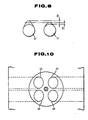
- exhaust cam lobes 6′ and 7′ are constructed so that the maximum lift L2 of one exhaust valve 2 is about one half of the maximum life L1 of the other exhaust valve 1.
- the cam lobes 6′ and 7′ are constructed so that the valve opening speed of the exhaust valve 2 is about half of that of the exhaust valve 1.
- the maximum lift L1 of the exhaust valve 1 is set so as to be substantially equal to the maximum lift of the intake valves 3 and 4.
- this embodiment is substantially similar to the previous embodiment described with reference to Figs. 1 to 5 and can produce substantially the same effect.
- a four-stroke cylcle internal combustion engine is shown as being provided with two exhaust valves 11 and 12 and two intake valves 13 and 14 per cylinder.
- the intake valves 13 and 14 are driven by a camshaft 16 at a predetermined valve timing shown in Fig. 16.
- Disposed between the exhaust valves 11 and 12 and a camshaft 15 is a variable valve operating mechanism for varying the valve opening and closing timings and valve lift of one exhaust valve 11.
- variable valve operating mechanism 20 as shown in Figs. 11 and 12, includes a pair of arms 22 and 22 respectively brought into sliding contact with the valve heads of the exhaust valves 11 and 12, a control cam 23 supporting one end of each arm 22 and a lever 21 interposed between each arm 22 and the camshaft 15.
- the camshaft 15 is driven to rotate in unison with the engine.
- Each lever 21 has one end supported by a hydraulic pivot 24 and the other end brought into sliding contact with the camshaft 15 so as to swing and thereby drive each one of the exhaust valves 11 and 12 to open and close.
- the control cam 23 is formed with a variable timing cam lobe 25 and a fixed timing cam lobe 26.
- the profile of the variable timing cam lobe 25, as shown in Fig. 13, has three lift portions I, II and III.
- the profile of the fixed timing cam lobe 26, as shown in Fig. 14, is a circle concentric with the axis of rotation of the control cam 23.
- the control cam 23 is rotatably supported by a cylinder head 17 and has a concentric opening through which a control shaft 27 extends.
- the control cam 23 is connected to the control shaft 27 with a spring 28 so as to be rotatable in relation to the control shaft 27.
- the control shaft 27 is driven to rotate by a stepping motor 29.
- the operation of the stepping motor 29 is controlled by a control unit 30 in such a manner as will be described hereinafter.
- the lever 21 is selectively supported by one of the lift portions I, II and III of the control cam 23 depending upon the rotational or angular position of same, whereby to selectively displace vertically. Since the lower face 21A of each lever 21 is protrusively arcuated in the longitudinal direction, vertical displacement of the support point of the lever 21 causes displacement of the contact point between the lever 21 and the arm 22 in the longitudinal direction thereof, whereby to effect three steps of variations of the the valve timing and valve lift of the exhaust valve 11.
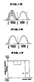
- Fig. 15 is a valve timing diagram for the exhaust valve 11 and the intake valves 13 and 14. As seen from this diagram, when the arm 22 is supported by the lift portion "I" of the control cam 23, the exhaust valve 11 starts opening at the bottom dead center after which the exhaust stroke begins and fullly closes in advance of the top dead center after which the intake stroke begins, thus not causing any valve overlap.
- the exhaust valve 11 starts opening in advance of the bottom dead center after which the exhaust stroke begins and fully closes in retard of the top dead center after which the intake stroke begins, thus causing a predetermined valve overlap.
- the exhaust valve 11 effects such a valve opening and closing timing and valve lift that is substantially intermediate between those effect when the lift portions I and III are selected to support the arm 22.
- Fig. 16 is a valve timing diagram for the fixed timing exhaust valve 12 and the fixed timing intake valves 3 and 4.
- the fixed timing exhaust valve 12 is adapted to effect a valve lift and a valve opening and closing timing equal to that effected when the lift portion "III" is selected to support the arm 22.
- the control unit 30 is adapted to read the rotational or angular position of the control cam 23 based on the map shown in Fig. 8 in response to an engine speed signal and a throttle opening signal and supplies a control signal to the stepping motor 29.
- the map is designed so that the lift portion "I” is selected to support the arm 22 in the middle-speed high-load operation range of the engine corresponding to the operation range in which the drop of the engine output torque occurs, the lift portion “II” is selected to support the arm 22 in the low to middle speed operation range other than the above described middle-speed high-load operation range and the lift portion "III” is selected to support the arm 22 in the high speed operation range.
- the fixed timing exhaust valve 12 and the intake valves 13 and 14 are operated so as to cause a predetermined valve overlap.
- the variable timing exhaust valve 11 is adapted to be driven by way of the lift portion "II"
- variable timing exhaust valve 11 is driven to open and close by way of the lift portion "III" of the control cam 23 and therefore effect the same valve lift and timing as the fixed timing exhaust valve 12.
- Both of the exhaust valves 11 and 12 have a predetermined valve overlap with the intake valves 13 and 14, thus supplying a large quantity of mixture into the cylinder by utilizing the inertia of the intake mixture and increasing the output torque.
- variable timing exhaust valve 11 is driven to open and close by way of the lift portion "I" so as to largely differ in the valve lift and timing from the fixed exhaust valve 12.
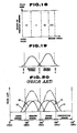
- the angular position of the control cam 23 may be determined by using the map shown in Fig. 18.
- the map of Fig. 18 is adapted to determine the angular position of the control cam 23 irrespectively of the engine load and to select the lift portion "I" at a predetermined middle speed range in which the drop of the engine output occurs, the lift portion "II” at a low to middle speed range other than the above described middle speed range and the lift portion "III" at a high speed range.
- the fixed timing exhaust valve 12 may be set so as to be equal in the opening and closing timings to the variable timing exhaust valve 12 obtained when the lift portion "III" is selected and to be smaller in the maximum valve lift, i.e., in the valve opening and closing speeds than the same.
Landscapes
- Engineering & Computer Science (AREA)
- Mechanical Engineering (AREA)
- General Engineering & Computer Science (AREA)
- Chemical & Material Sciences (AREA)
- Combustion & Propulsion (AREA)
- Output Control And Ontrol Of Special Type Engine (AREA)
- Valve Device For Special Equipments (AREA)
- Valve-Gear Or Valve Arrangements (AREA)
Abstract
Description
- The present invention relates to a valve operating mechanism for an internal combustion engine having a plurality of exhaust valves per cylinder.
- In an internal combustion engine for automotive vehicles, etc., having a plurality of exhaust valves and a plurality of intake valves per cylinder, it has been proposed to operate at the different valve timings the exhaust valves and the intake valves, respectively.
- A prior art valve operating mechanism of the above described kind, as for example disclosed in Japanese Patent Publication No. 49-17967, is adapted to operate two exhaust valves and two intake valves of a four-stroke cycle four-valves-per-cylinder internal combustion engine at the valve timings as shown in Fig. 7. That is, the valve timings E1 and E2 of the two exhaust valves and the valve timings I1 and I2 of the two intake valves respectively have such predetermined phase differences that at the positions of the piston adjacent the top dead center in the transition from the exhaust stroke to the intake stroke a set of one exhaust valve and one intake valve are closed and a set of the other exhaust valve and the other intake valve are opened with a view to increaing the velocity of flow of the fresh intake mixture within the cylinder and thereby improving the scavenging efficiency. Further, at the position of the piston adjacent the bottom dead center in the transition from the intake stroke to the compression stroke, only one of the intake valves is opened to cause a swirl of the intake mixture for thereby improving the combustibility during high-speed high-load operation of the engine.
- In the valve operating mechanism of the above described type, a phase difference is provided to the timings at which the two exhaust valves fully close. Due to this, the effective area of the opening defined by the exhaust valves at the time of the valve overlap in which the intake and exhaust valves are held open simultaneously is small, thus resulting in that a long valve overlapping period is necessitated in order to fully attain an inertia supercharging effect of the intake mixture during high-speed high-load operation of the engine.
- However, when the valve overlapping period is set to be long, the exhaust gases are caused to flow reversely into the cylinder being drawn by a large intake vacuum though the area of the opening defined by the exhaust valves is small, thus increasing the quantity of the residual gases during low-speed low-load operation of the engine in which the supply of intake mixture is small, thus largely deteriorating the combustibility.
- In accordance with the present invention, there is provided a novel valve operating mechanism for an internal combustion engine having a plurality of exhaust valves per cylinder.
- The valve operating mechanism comprises means for driving the exhaust valves at such a valve timing that makes opening of the exhaust valves cause blowdown pressures with a phase difference.
- This structure is effective for solving the above noted problems inherent in the prior art device.
- It is accordingly an object of the present invention to provide a novel valve operating mechanism for an internal combustion engine having a plurality of exhaust valves per cylinder, which can reduce the variation magnitude of the blowdown pressure caused by the opening of the exhaust valves and thereby reduce the above noted drop of engine output torque.
- It is another object of the present invention to provide a novel valve operating mechanism of the above described character which can reduce the quantity of the exhaust gases reversely flowing into the cylinder due to valve overlap during low-speed low-load operation of the engine and attain the idling stability.
-
- Fig. 1 is a valve timing diagram according to an embodiment of the present invention;
- Fig. 2 is a side elevation of an exhaust valve operating camshaft utilized in the embodiment of Fig. 1;
- Fig. 3 is a diagram illustrating a variation amplitude of a pressure wave in an exhaust passage in the embodiment of Fig. 1 in comparison with that in the comparable prior art device;
- Fig. 4 is a diagram illustrating variations of an exhaust port pressure in the embodiment of Fig. 1 in comparison with that in the comparable prior art device;
- Fig. 5 is a graph depeicting variations of an enging output torque and a volumetric efficiency relative to an engine speed in the embodiment of Fig. 1 in comparison with that in the prior art device;
- Fig. 6 is a valve timing diagram according to another embodiment;
- Fig. 7 is a valve timing diagram according to a further embodiment;
- Fig. 8 is a schematic view of exhaust cam lobes employed in the embodiment of Fig. 7;
- Fig. 9 is a sectional view of a cylinder head incorporating a valve operating mechanism according to a further embodiment of the present invention;
- Fig. 10 is a view taken in the direction of the arrow "X" in Fig. 9;
- Fig. 11 is an exploded view of the valve operating mechanism of Fig. 9;
- Fig. 12 is a fragmentary top plan view of the valve operating mechanism of Fig. 9;
- Fig. 13 is a side elevational view of a variable timing cam employed in the valve operating mechanism of Fig. 9;
- Fig. 14 is a side elevational view of a stationary timing cam employed in the valve operating mecanism of Fig. 9;
- Fig. 15 is a variable valve timing diagram for the valve operating mechanism of the embodiment of Fig. 9;
- Fig. 16 is a stationary valve timing diagram for the valve operating mechanism of the embodiment of Fig. 9;
- Fig. 17 is a diagram depicting a control map for controlling the rotational position of the variable timing cam of Fig. 13;
- Fig. 18 is is a diagram similar to Fig. 17 but depicting another control map;
- Fig. 19 is a valve timing diagram according to a further embodiment of the present invention; and
- Fig. 20 is a valve timing diagram according to the prior art.
- Referring to Fig. 1, the curves E1 and E2 and the curve I depict valve timings for a four-stroke cycle four-valves-per-cylinder internal combustion engine according to an embodiment of the present invention.
- The curves E1 and E2 represent the valve timings of
exhaust valves exhaust valves exhaust valves exhaust valves - The curve "I" represents a valve timing common to intake
valves 3 and 4. Theintake valves 3 and 4 start opening in advance of the top dead center, reach a maximum lift point in the middle of the exhaust stroke and fully close in retard of the bottom dead center after which the compression stroke begins. With those valve timings, theexhaust valves intake valves 3 and 4 are given a predetermined valve overlapping angle about the top dead center. - Fig. 2 shows a camshaft 5 for the
exhaust valves cams 6 and 7 which are so profiled as to have a phase difference of ϑ/2 at the opening valve points and a phase difference of 0 (zero) at the closing valve points. - In Fig. 3, the dotted line curve indicates the pressure wave occurring in the exhaust passages downstream of the
exhaust valves exhaust valve 1 and a blowdown pressure (indicated by the two-dot-chain line curve) produced by the opening of theexhaust valve 2. Therefore, the vibration amplitude of the pressure wave in the embodiment of this invention can be smaller than that (indicated by the solid line curve) in the prior art device of which exhaust valves open at the same time, i.e., with the same phase. - Fig. 4 shows by the dotted line curve the pressure variations of the pressure wave measured under the condition that the engine is operated at the speed of 3600 rpm so that the pressure wave becomes positive in the place spaced by 120 mm downstream of the
exhaust valves exhaust valves - Fig. 5 shows, with respect to the embodiment of this invention and the prior art device, how the engine output torque and volumetric efficiency vary with variation of the engine rpm. From this graph, it will be understood that while in case of the prior art device there occurs a considerable drop or fall of the output toruqe and volumetric efficiency at or near the engine speed of 3600 rpm, a corresponding drop is smaller in case of this embodiment.
- The drop of the output torque is caused by the closure of the
exhaust valves exhaust valves exhaust valves - Further, by making the
exhaust valves exhaust valves exhaust valves intake valves 3 and 4, thus making it unnecessary to set the valve overalpping peiord to be so long. As a result, it becomes possible to retain the volumetric efficiency by utilizing the inertia of the intake mixture during high-speed high-load operation of the engine and at the same time prevent the exhaust gases from reversely flowing into the engine cylinder being drawn by the intake vacuum during low-speed low-load operation of the engine, thus preventing the combustibility from being deteriorated by the residual exhaust gases and thereby improving the idling stability, etc. - Fig. 6 shows another embodiment in which the engine is of the type having three exhaust valves per cylinder, and the exhaust valves start opening at different timings so as to provide phase differences ϑ1 and ϑ2 and fully close at the same time, i.e., synchronously with each other though closing movments of the exhaust valves are performed at different speeds.
- When this is the case, since three exhaust valves start opening with phase differences from each other, the blowdown pressures are produced at the three different timings, thus making it possible to further reduce the variation amplitude of the pressure wave occuring in the exhaust passage.
- Fig. 7 shows a further embodiment in which the valve timings E1 and E2 cause the
exhaust valves exhaust cam lobes 6′ and 7′ are constructed so that the maximum lift L2 of oneexhaust valve 2 is about one half of the maximum life L1 of theother exhaust valve 1. Further, thecam lobes 6′ and 7′ are constructed so that the valve opening speed of theexhaust valve 2 is about half of that of theexhaust valve 1. In the meantime, the maximum lift L1 of theexhaust valve 1 is set so as to be substantially equal to the maximum lift of theintake valves 3 and 4. - Except for the above, this embodiment is substantially similar to the previous embodiment described with reference to Figs. 1 to 5 and can produce substantially the same effect.
- Referring to Figs. 9 to 17, a further embodiment will be described.
- In Figs. 9 and 10, a four-stroke cylcle internal combustion engine is shown as being provided with two
exhaust valves intake valves intake valves camshaft 16 at a predetermined valve timing shown in Fig. 16. Disposed between theexhaust valves camshaft 15 is a variable valve operating mechanism for varying the valve opening and closing timings and valve lift of oneexhaust valve 11. - The variable
valve operating mechanism 20, as shown in Figs. 11 and 12, includes a pair ofarms exhaust valves control cam 23 supporting one end of eacharm 22 and alever 21 interposed between eacharm 22 and thecamshaft 15. - The
camshaft 15 is driven to rotate in unison with the engine. Eachlever 21 has one end supported by ahydraulic pivot 24 and the other end brought into sliding contact with thecamshaft 15 so as to swing and thereby drive each one of theexhaust valves - The
control cam 23 is formed with a variabletiming cam lobe 25 and a fixedtiming cam lobe 26. The profile of the variabletiming cam lobe 25, as shown in Fig. 13, has three lift portions I, II and III. In contrast to this, the profile of the fixedtiming cam lobe 26, as shown in Fig. 14, is a circle concentric with the axis of rotation of thecontrol cam 23. - The
control cam 23 is rotatably supported by acylinder head 17 and has a concentric opening through which acontrol shaft 27 extends. Thecontrol cam 23 is connected to thecontrol shaft 27 with aspring 28 so as to be rotatable in relation to thecontrol shaft 27. Thecontrol shaft 27 is driven to rotate by a steppingmotor 29. The operation of the steppingmotor 29 is controlled by acontrol unit 30 in such a manner as will be described hereinafter. - The
lever 21 is selectively supported by one of the lift portions I, II and III of thecontrol cam 23 depending upon the rotational or angular position of same, whereby to selectively displace vertically. Since thelower face 21A of eachlever 21 is protrusively arcuated in the longitudinal direction, vertical displacement of the support point of thelever 21 causes displacement of the contact point between thelever 21 and thearm 22 in the longitudinal direction thereof, whereby to effect three steps of variations of the the valve timing and valve lift of theexhaust valve 11. - Fig. 15 is a valve timing diagram for the
exhaust valve 11 and theintake valves arm 22 is supported by the lift portion "I" of thecontrol cam 23, theexhaust valve 11 starts opening at the bottom dead center after which the exhaust stroke begins and fullly closes in advance of the top dead center after which the intake stroke begins, thus not causing any valve overlap. - When the
arm 22 is supported by the lift portion "III" of thecontrol cam 23, theexhaust valve 11 starts opening in advance of the bottom dead center after which the exhaust stroke begins and fully closes in retard of the top dead center after which the intake stroke begins, thus causing a predetermined valve overlap. - When the
arm 22 is supported by the lift portion "II" of thecontrol cam 23, theexhaust valve 11 effects such a valve opening and closing timing and valve lift that is substantially intermediate between those effect when the lift portions I and III are selected to support thearm 22. - Fig. 16 is a valve timing diagram for the fixed
timing exhaust valve 12 and the fixedtiming intake valves 3 and 4. The fixedtiming exhaust valve 12 is adapted to effect a valve lift and a valve opening and closing timing equal to that effected when the lift portion "III" is selected to support thearm 22. - The
control unit 30 is adapted to read the rotational or angular position of thecontrol cam 23 based on the map shown in Fig. 8 in response to an engine speed signal and a throttle opening signal and supplies a control signal to the steppingmotor 29. In this instance, the map is designed so that the lift portion "I" is selected to support thearm 22 in the middle-speed high-load operation range of the engine corresponding to the operation range in which the drop of the engine output torque occurs, the lift portion "II" is selected to support thearm 22 in the low to middle speed operation range other than the above described middle-speed high-load operation range and the lift portion "III" is selected to support thearm 22 in the high speed operation range. - The operation will now be described.
- During low to middle speed operation of the engine, the fixed
timing exhaust valve 12 and theintake valves timing exhaust valve 11 is adapted to be driven by way of the lift portion "II", it scarcely cause a valve overlap with theintake valves exhaust valve 11 reversely into the cylinder being drawn by the intake vacuum, thus making it possible to prevent the combustibility from being deteriorated by the residual gases and thereby improving the idling stability, etc. - During high speed operation of the engine, the variable
timing exhaust valve 11 is driven to open and close by way of the lift portion "III" of thecontrol cam 23 and therefore effect the same valve lift and timing as the fixedtiming exhaust valve 12. Both of theexhaust valves intake valves - In the meantime, a pressure wave is caused in the exhaust passage in response to opening of the
exhaust valves exhaust valves exhaust valves - At the engine speed range in which the above described drop of the engine output torque occurs, the variable
timing exhaust valve 11 is driven to open and close by way of the lift portion "I" so as to largely differ in the valve lift and timing from the fixedexhaust valve 12. By this, this emobidment can produce substantially the same effect of the previous embodiment described with reference to Fig. 3. - In place of the map of Fig. 17, the angular position of the
control cam 23 may be determined by using the map shown in Fig. 18. The map of Fig. 18 is adapted to determine the angular position of thecontrol cam 23 irrespectively of the engine load and to select the lift portion "I" at a predetermined middle speed range in which the drop of the engine output occurs, the lift portion "II" at a low to middle speed range other than the above described middle speed range and the lift portion "III" at a high speed range. - Further, as shown in Fig. 19, the fixed
timing exhaust valve 12 may be set so as to be equal in the opening and closing timings to the variabletiming exhaust valve 12 obtained when the lift portion "III" is selected and to be smaller in the maximum valve lift, i.e., in the valve opening and closing speeds than the same.
Claims (14)
means for driving said exhaust valves at such a valve timing that makes opening of said exhaust valves cause blowdown pressures with a phase difference.
means for driving said exhaust valves at such a valve timing that makes said exhaust valves open at the different times and fully close at the same time.
means for driving said exhaust valves at such a valve timing that makes said exhaust valves open and close at the same time and at different opening speeds so as to effect different maximum valve lifts.
means for driving said exhaust valves at variable relative timings; and
means for controlling said driving means so as to vary said relative timings in accordance with variations of operation of said engine.
first drive means for driving one of said exhaust valves at a fixed valve timing and lift;
second drive means for driving the other of said exhaust valves at a variable valve timing and lift; and
control means for controlling said second drive means so as to vary said valve timing of said other exhaust valve in accordance with variations of operation of said engine.
Applications Claiming Priority (6)
| Application Number | Priority Date | Filing Date | Title |
|---|---|---|---|
| JP187044/87U | 1987-12-08 | ||
| JP18704487U JPH0191006U (en) | 1987-12-08 | 1987-12-08 | |
| JP31719087A JPH01159417A (en) | 1987-12-15 | 1987-12-15 | Valve system for internal combustion engine |
| JP190257/87U | 1987-12-15 | ||
| JP317190/87 | 1987-12-15 | ||
| JP19025787U JPH0193311U (en) | 1987-12-15 | 1987-12-15 |
Publications (2)
| Publication Number | Publication Date |
|---|---|
| EP0319956A1 true EP0319956A1 (en) | 1989-06-14 |
| EP0319956B1 EP0319956B1 (en) | 1992-10-28 |
Family
ID=27325832
Family Applications (1)
| Application Number | Title | Priority Date | Filing Date |
|---|---|---|---|
| EP88120459A Expired - Lifetime EP0319956B1 (en) | 1987-12-08 | 1988-12-07 | Valve operating mechanism |
Country Status (4)
| Country | Link |
|---|---|
| US (1) | US4964375A (en) |
| EP (1) | EP0319956B1 (en) |
| KR (1) | KR890010397A (en) |
| DE (1) | DE3875593T2 (en) |
Cited By (15)
| Publication number | Priority date | Publication date | Assignee | Title |
|---|---|---|---|---|
| DE3933021A1 (en) * | 1989-10-04 | 1991-04-18 | Ford Werke Ag | CAMSHAFT FOR MULTI-VALVE INTERNAL COMBUSTION ENGINES |
| WO1991013241A1 (en) * | 1990-02-26 | 1991-09-05 | King Brian T | Valve duration and lift variator for internal combustion engines |
| EP0453416A1 (en) * | 1990-04-20 | 1991-10-23 | FIAT AUTO S.p.A. | Motor-vehicle internal combustion engine with differentially opened valves |
| FR2688828A1 (en) * | 1992-03-20 | 1993-09-24 | Daimler Benz Ag | ADJUSTABLE VALVE CONTROL MECHANISM IN AN INTERNAL COMBUSTION ENGINE. |
| EP0638706A1 (en) * | 1993-08-05 | 1995-02-15 | Bayerische Motoren Werke Aktiengesellschaft | Valve actuating mechanism of an internal combustion engine |
| EP0761950A1 (en) * | 1995-09-12 | 1997-03-12 | Toyota Jidosha Kabushiki Kaisha | A valve timing control device for an internal combustion engine |
| EP0802306A1 (en) * | 1996-04-19 | 1997-10-22 | Toyota Jidosha Kabushiki Kaisha | Valve system for engine |
| WO2001036793A1 (en) * | 1999-11-13 | 2001-05-25 | Dr.Ing.H.C. F. Porsche Aktiengesellschaft | Multiple cylinder internal combustion engine |
| FR2806752A1 (en) * | 2000-02-28 | 2001-09-28 | Toyota Motor Co Ltd | INTERNAL COMBUSTION ENGINE |
| FR2860552A1 (en) * | 2003-10-02 | 2005-04-08 | Peugeot Citroen Automobiles Sa | METHOD FOR CONTROLLING A SUPERCURRENT MOTOR AND CORRESPONDING INTERNAL COMBUSTION ENGINE |
| WO2005111400A1 (en) * | 2004-05-13 | 2005-11-24 | Audi Ag | Method for operating an internal combustion engine, and internal combustion engine for carrying out said method |
| EP1479878A3 (en) * | 2003-05-23 | 2008-12-31 | Peugeot Citroen Automobiles | Valve arrangement in an internal combustion engine |
| CN105275622A (en) * | 2014-05-28 | 2016-01-27 | 福特环球技术公司 | Supercharged applied ignition internal combustion engine with exhaust-gas turbocharging and method for operating an internal combustion engine of said type |
| GB2531807A (en) * | 2014-11-03 | 2016-05-04 | Ford Global Tech Llc | Camshaft for an engine |
| RU2633336C2 (en) * | 2012-06-19 | 2017-10-11 | ФОРД ГЛОУБАЛ ТЕКНОЛОДЖИЗ, ЭлЭлСи | Internal combustion engine with forced ignition and method of internal combustion engine with forced ignition control |
Families Citing this family (20)
| Publication number | Priority date | Publication date | Assignee | Title |
|---|---|---|---|---|
| JP2736997B2 (en) * | 1989-04-27 | 1998-04-08 | 本田技研工業株式会社 | Valve drive device and valve drive method for internal combustion engine |
| JP3043349B2 (en) * | 1989-12-12 | 2000-05-22 | 株式会社いすゞセラミックス研究所 | Electromagnetic force valve drive control device |
| JPH04175406A (en) * | 1990-11-07 | 1992-06-23 | Sanshin Ind Co Ltd | 2-cycle internal combustion engine |
| JP2982581B2 (en) * | 1993-10-14 | 1999-11-22 | 日産自動車株式会社 | Variable valve train for internal combustion engine |
| JPH0914006A (en) * | 1995-06-27 | 1997-01-14 | Yamaha Motor Co Ltd | Valve operation control method for internal combustion engine |
| US7281527B1 (en) | 1996-07-17 | 2007-10-16 | Bryant Clyde C | Internal combustion engine and working cycle |
| US8215292B2 (en) | 1996-07-17 | 2012-07-10 | Bryant Clyde C | Internal combustion engine and working cycle |
| US7222614B2 (en) | 1996-07-17 | 2007-05-29 | Bryant Clyde C | Internal combustion engine and working cycle |
| SE514969C2 (en) * | 1999-09-15 | 2001-05-21 | Saab Automobile | Internal combustion engine |
| US7201121B2 (en) | 2002-02-04 | 2007-04-10 | Caterpillar Inc | Combustion engine including fluidically-driven engine valve actuator |
| US7178492B2 (en) | 2002-05-14 | 2007-02-20 | Caterpillar Inc | Air and fuel supply system for combustion engine |
| US6688280B2 (en) | 2002-05-14 | 2004-02-10 | Caterpillar Inc | Air and fuel supply system for combustion engine |
| JP2003314309A (en) * | 2002-04-25 | 2003-11-06 | Hitachi Unisia Automotive Ltd | Variable valve control device for internal combustion engine |
| US7191743B2 (en) | 2002-05-14 | 2007-03-20 | Caterpillar Inc | Air and fuel supply system for a combustion engine |
| US7252054B2 (en) | 2002-05-14 | 2007-08-07 | Caterpillar Inc | Combustion engine including cam phase-shifting |
| FR2864153B1 (en) * | 2003-12-18 | 2006-02-17 | Inst Francais Du Petrole | METHOD FOR CONTROLLING AN INTERNAL COMBUSTION ENGINE SUPERCURRENT TO AT LEAST TWO CYLINDERS AND ENGINE USING SUCH A METHOD |
| GB2457326B (en) * | 2008-10-17 | 2010-01-06 | Univ Loughborough | An exhaust arrangement for an internal combustion engine |
| US9599036B2 (en) * | 2014-07-31 | 2017-03-21 | Ford Global Technologies, Llc | Method and system for diagonal blow-through exhaust gas scavenging |
| DE102022004788A1 (en) * | 2022-12-19 | 2024-06-20 | Mercedes-Benz Group AG | Internal combustion engine for a motor vehicle, in particular for a motor vehicle, and motor vehicle |
| DE102022004789A1 (en) * | 2022-12-19 | 2024-06-20 | Mercedes-Benz Group AG | Internal combustion engine for a motor vehicle, in particular for a motor vehicle, and motor vehicle |
Citations (3)
| Publication number | Priority date | Publication date | Assignee | Title |
|---|---|---|---|---|
| DE3332789A1 (en) * | 1982-09-10 | 1984-03-15 | Toyo Kogyo Co. Ltd., Hiroshima | VALVE CONTROL DEVICE FOR AN INTERNAL COMBUSTION ENGINE |
| GB2172051A (en) * | 1985-03-06 | 1986-09-10 | Nissan Motor | Multi-valve internal combustion engine |
| DE3621080A1 (en) * | 1985-06-24 | 1987-01-02 | Nissan Motor | VALVE TIMING DEVICE FOR COMBUSTION ENGINES WITH SEVERAL INLET VALVES PER CYLINDER |
Family Cites Families (11)
| Publication number | Priority date | Publication date | Assignee | Title |
|---|---|---|---|---|
| US3334618A (en) * | 1964-05-26 | 1967-08-08 | Funiciello Orazio | Four stroke high r.p.m. internal combustion engine for racing purposes |
| JPS557942B2 (en) * | 1972-06-07 | 1980-02-29 | ||
| US4108119A (en) * | 1977-01-19 | 1978-08-22 | Mcwhorter Edward Milton | Bottom cycle manifold for four-stroke internal combustion engines |
| JPS55151115A (en) * | 1979-05-11 | 1980-11-25 | Nissan Motor Co Ltd | Exhaust-gas purifying structure for internal combustion engine |
| IT1201034B (en) * | 1983-02-24 | 1989-01-27 | Mario Anfusio | INTERNAL COMBUSTION ALTERNATIVE ENGINE WITH MULTIPLE VALVE CYLINDERS |
| GB2161212A (en) * | 1984-04-07 | 1986-01-08 | Jaguar Cars | Cracking fuel and supplying to an internal combustion engine |
| JP2554245B2 (en) * | 1985-04-30 | 1996-11-13 | マツダ株式会社 | Single-over headed cam type engine |
| JPS62121811A (en) * | 1985-07-31 | 1987-06-03 | Honda Motor Co Ltd | Internal combustion engine valve train |
| JPS6357806A (en) * | 1986-08-27 | 1988-03-12 | Honda Motor Co Ltd | Internal combustion engine valve train |
| JPH0199036A (en) * | 1987-10-13 | 1989-04-17 | Toshiba Corp | Radiograph reader |
| US4765287A (en) * | 1987-11-02 | 1988-08-23 | Taylor Bill A | Slide valve apparatus for internal combustion engine |
-
1988
- 1988-12-07 DE DE8888120459T patent/DE3875593T2/en not_active Expired - Fee Related
- 1988-12-07 EP EP88120459A patent/EP0319956B1/en not_active Expired - Lifetime
- 1988-12-07 US US07/280,856 patent/US4964375A/en not_active Expired - Fee Related
- 1988-12-08 KR KR1019880016317A patent/KR890010397A/en not_active Abandoned
Patent Citations (3)
| Publication number | Priority date | Publication date | Assignee | Title |
|---|---|---|---|---|
| DE3332789A1 (en) * | 1982-09-10 | 1984-03-15 | Toyo Kogyo Co. Ltd., Hiroshima | VALVE CONTROL DEVICE FOR AN INTERNAL COMBUSTION ENGINE |
| GB2172051A (en) * | 1985-03-06 | 1986-09-10 | Nissan Motor | Multi-valve internal combustion engine |
| DE3621080A1 (en) * | 1985-06-24 | 1987-01-02 | Nissan Motor | VALVE TIMING DEVICE FOR COMBUSTION ENGINES WITH SEVERAL INLET VALVES PER CYLINDER |
Non-Patent Citations (1)
| Title |
|---|
| PATENT ABSTRACTS OF JAPAN, vol. 7, no. 31 (M-192)[1176], 8th February 1983; & JP-A-57 186 009 (YAMAHA HATSUDOKI K.K.) 16-11-1982 * |
Cited By (23)
| Publication number | Priority date | Publication date | Assignee | Title |
|---|---|---|---|---|
| DE3933021A1 (en) * | 1989-10-04 | 1991-04-18 | Ford Werke Ag | CAMSHAFT FOR MULTI-VALVE INTERNAL COMBUSTION ENGINES |
| WO1991005147A1 (en) * | 1989-10-04 | 1991-04-18 | Ford Motor Company Limited | Camshaft for multi-valve internal combustion engine |
| DE3933021C3 (en) * | 1989-10-04 | 1998-06-10 | Ford Werke Ag | Camshafts for the valve train of internal combustion engines |
| WO1991013241A1 (en) * | 1990-02-26 | 1991-09-05 | King Brian T | Valve duration and lift variator for internal combustion engines |
| EP0453416A1 (en) * | 1990-04-20 | 1991-10-23 | FIAT AUTO S.p.A. | Motor-vehicle internal combustion engine with differentially opened valves |
| FR2688828A1 (en) * | 1992-03-20 | 1993-09-24 | Daimler Benz Ag | ADJUSTABLE VALVE CONTROL MECHANISM IN AN INTERNAL COMBUSTION ENGINE. |
| EP0638706A1 (en) * | 1993-08-05 | 1995-02-15 | Bayerische Motoren Werke Aktiengesellschaft | Valve actuating mechanism of an internal combustion engine |
| EP0761950A1 (en) * | 1995-09-12 | 1997-03-12 | Toyota Jidosha Kabushiki Kaisha | A valve timing control device for an internal combustion engine |
| EP0802306A1 (en) * | 1996-04-19 | 1997-10-22 | Toyota Jidosha Kabushiki Kaisha | Valve system for engine |
| KR100749232B1 (en) * | 1999-11-13 | 2007-08-13 | 독터. 인제니어.하.체.에프.포르쉐악티엔게젤샤프트 | Multi-cylinder internal combustion engine |
| US6397802B1 (en) | 1999-11-13 | 2002-06-04 | Dr. Ing. H.C.F. Porsche Ag | Multiple cylinder internal combustion engine |
| WO2001036793A1 (en) * | 1999-11-13 | 2001-05-25 | Dr.Ing.H.C. F. Porsche Aktiengesellschaft | Multiple cylinder internal combustion engine |
| FR2806752A1 (en) * | 2000-02-28 | 2001-09-28 | Toyota Motor Co Ltd | INTERNAL COMBUSTION ENGINE |
| EP1479878A3 (en) * | 2003-05-23 | 2008-12-31 | Peugeot Citroen Automobiles | Valve arrangement in an internal combustion engine |
| FR2860552A1 (en) * | 2003-10-02 | 2005-04-08 | Peugeot Citroen Automobiles Sa | METHOD FOR CONTROLLING A SUPERCURRENT MOTOR AND CORRESPONDING INTERNAL COMBUSTION ENGINE |
| EP1520966A3 (en) * | 2003-10-02 | 2006-02-08 | Peugeot Citroen Automobiles S.A. | Method for controlling a supercharged engine, and corresponding engine |
| WO2005111400A1 (en) * | 2004-05-13 | 2005-11-24 | Audi Ag | Method for operating an internal combustion engine, and internal combustion engine for carrying out said method |
| US8100099B2 (en) | 2004-05-13 | 2012-01-24 | Audi, Ag | Method for operating an internal combustion engine, and internal combustion engine for carrying out said method |
| RU2633336C2 (en) * | 2012-06-19 | 2017-10-11 | ФОРД ГЛОУБАЛ ТЕКНОЛОДЖИЗ, ЭлЭлСи | Internal combustion engine with forced ignition and method of internal combustion engine with forced ignition control |
| CN105275622A (en) * | 2014-05-28 | 2016-01-27 | 福特环球技术公司 | Supercharged applied ignition internal combustion engine with exhaust-gas turbocharging and method for operating an internal combustion engine of said type |
| CN105275622B (en) * | 2014-05-28 | 2020-03-27 | 福特环球技术公司 | Supercharged applied-ignition internal combustion engine with exhaust-gas turbocharging and method for operating an internal combustion engine of said type |
| GB2531807A (en) * | 2014-11-03 | 2016-05-04 | Ford Global Tech Llc | Camshaft for an engine |
| RU2702775C2 (en) * | 2014-11-03 | 2019-10-11 | Форд Глобал Текнолоджиз, Ллк | Engine comprising one or more camshafts, engine cylinder valves control method and controller |
Also Published As
| Publication number | Publication date |
|---|---|
| EP0319956B1 (en) | 1992-10-28 |
| KR890010397A (en) | 1989-08-08 |
| DE3875593D1 (en) | 1992-12-03 |
| DE3875593T2 (en) | 1993-03-11 |
| US4964375A (en) | 1990-10-23 |
Similar Documents
| Publication | Publication Date | Title |
|---|---|---|
| US4964375A (en) | Valve operating mechanism | |
| US6357405B1 (en) | Valve drive mechanism of four-stroke cycle engine | |
| JP2843614B2 (en) | Two-cycle diesel engine | |
| JPS6148614B2 (en) | ||
| JPH06129271A (en) | 4-cycle engine | |
| JPH0225005B2 (en) | ||
| JP4089408B2 (en) | High compression ratio cycle engine | |
| JPH07259655A (en) | Exhaust gas recirculation device | |
| JPH09317520A (en) | Intake valve control device and control method for internal combustion engine with supercharger | |
| JP4151395B2 (en) | High expansion ratio cycle engine | |
| JPH1193710A (en) | Exhaust valve control device for 2-stroke diesel engine with turbocharger | |
| JP4089407B2 (en) | High expansion ratio cycle engine | |
| JP3726364B2 (en) | Intake valve control device and control method for supercharged internal combustion engine | |
| JPS60150459A (en) | Engine with fuel injection device | |
| JP2687718B2 (en) | Cam switching control device for internal combustion engine | |
| JP2004183512A (en) | High expansion ratio cycle engine | |
| JP2001263108A (en) | Intake valve drive control device for internal combustion engine | |
| JP3536519B2 (en) | Intake valve control device and control method for internal combustion engine | |
| JPS61187543A (en) | Control method of variable valve-timing engine | |
| JPH0621579B2 (en) | Variable valve timing engine control method | |
| JPH059610B2 (en) | ||
| JPH0544528B2 (en) | ||
| US6615798B2 (en) | Internal combustion engine having multiple intake valves, one valve adapted for higher speed | |
| JP2533753B2 (en) | Engine valve timing controller | |
| JPS6131145Y2 (en) |
Legal Events
| Date | Code | Title | Description |
|---|---|---|---|
| PUAI | Public reference made under article 153(3) epc to a published international application that has entered the european phase |
Free format text: ORIGINAL CODE: 0009012 |
|
| 17P | Request for examination filed |
Effective date: 19881207 |
|
| AK | Designated contracting states |
Kind code of ref document: A1 Designated state(s): DE GB |
|
| 17Q | First examination report despatched |
Effective date: 19901217 |
|
| GRAA | (expected) grant |
Free format text: ORIGINAL CODE: 0009210 |
|
| AK | Designated contracting states |
Kind code of ref document: B1 Designated state(s): DE GB |
|
| REF | Corresponds to: |
Ref document number: 3875593 Country of ref document: DE Date of ref document: 19921203 |
|
| PLBE | No opposition filed within time limit |
Free format text: ORIGINAL CODE: 0009261 |
|
| STAA | Information on the status of an ep patent application or granted ep patent |
Free format text: STATUS: NO OPPOSITION FILED WITHIN TIME LIMIT |
|
| 26N | No opposition filed | ||
| PGFP | Annual fee paid to national office [announced via postgrant information from national office to epo] |
Ref country code: GB Payment date: 19941129 Year of fee payment: 7 |
|
| PGFP | Annual fee paid to national office [announced via postgrant information from national office to epo] |
Ref country code: DE Payment date: 19941208 Year of fee payment: 7 |
|
| PG25 | Lapsed in a contracting state [announced via postgrant information from national office to epo] |
Ref country code: GB Effective date: 19951207 |
|
| GBPC | Gb: european patent ceased through non-payment of renewal fee |
Effective date: 19951207 |
|
| PG25 | Lapsed in a contracting state [announced via postgrant information from national office to epo] |
Ref country code: DE Effective date: 19960903 |