EP0319764A2 - Connector with injection site - Google Patents
Connector with injection site Download PDFInfo
- Publication number
- EP0319764A2 EP0319764A2 EP88119376A EP88119376A EP0319764A2 EP 0319764 A2 EP0319764 A2 EP 0319764A2 EP 88119376 A EP88119376 A EP 88119376A EP 88119376 A EP88119376 A EP 88119376A EP 0319764 A2 EP0319764 A2 EP 0319764A2
- Authority
- EP
- European Patent Office
- Prior art keywords
- connecting means
- connector
- injection site
- needle
- infusion
- Prior art date
- Legal status (The legal status is an assumption and is not a legal conclusion. Google has not performed a legal analysis and makes no representation as to the accuracy of the status listed.)
- Granted
Links
- 238000002347 injection Methods 0.000 title claims abstract description 115
- 239000007924 injection Substances 0.000 title claims abstract description 115
- 238000001802 infusion Methods 0.000 claims abstract description 144
- 239000012530 fluid Substances 0.000 claims abstract description 44
- 239000013013 elastic material Substances 0.000 claims abstract description 10
- 238000001990 intravenous administration Methods 0.000 claims description 25
- 208000015181 infectious disease Diseases 0.000 abstract description 4
- 229920001971 elastomer Polymers 0.000 description 33
- 239000005060 rubber Substances 0.000 description 33
- 239000003814 drug Substances 0.000 description 24
- 229940079593 drug Drugs 0.000 description 24
- 239000007788 liquid Substances 0.000 description 24
- 239000000463 material Substances 0.000 description 16
- 238000002560 therapeutic procedure Methods 0.000 description 9
- 239000000243 solution Substances 0.000 description 7
- 238000000034 method Methods 0.000 description 6
- 239000011347 resin Substances 0.000 description 6
- 229920005989 resin Polymers 0.000 description 6
- BZHJMEDXRYGGRV-UHFFFAOYSA-N Vinyl chloride Chemical compound ClC=C BZHJMEDXRYGGRV-UHFFFAOYSA-N 0.000 description 4
- 210000003462 vein Anatomy 0.000 description 4
- 235000015097 nutrients Nutrition 0.000 description 3
- -1 polyethylene Polymers 0.000 description 3
- 229920002379 silicone rubber Polymers 0.000 description 3
- 239000004945 silicone rubber Substances 0.000 description 3
- 244000043261 Hevea brasiliensis Species 0.000 description 2
- 239000004698 Polyethylene Substances 0.000 description 2
- 229920003049 isoprene rubber Polymers 0.000 description 2
- 229920003052 natural elastomer Polymers 0.000 description 2
- 229920001194 natural rubber Polymers 0.000 description 2
- 229920001084 poly(chloroprene) Polymers 0.000 description 2
- 229920000573 polyethylene Polymers 0.000 description 2
- 229920003002 synthetic resin Polymers 0.000 description 2
- 239000000057 synthetic resin Substances 0.000 description 2
- 235000021476 total parenteral nutrition Nutrition 0.000 description 2
- 241000894006 Bacteria Species 0.000 description 1
- 229920000181 Ethylene propylene rubber Polymers 0.000 description 1
- 229920000459 Nitrile rubber Polymers 0.000 description 1
- 239000004952 Polyamide Substances 0.000 description 1
- 239000005062 Polybutadiene Substances 0.000 description 1
- 239000004743 Polypropylene Substances 0.000 description 1
- 239000004793 Polystyrene Substances 0.000 description 1
- 229920006311 Urethane elastomer Polymers 0.000 description 1
- 229920000800 acrylic rubber Polymers 0.000 description 1
- XECAHXYUAAWDEL-UHFFFAOYSA-N acrylonitrile butadiene styrene Chemical compound C=CC=C.C=CC#N.C=CC1=CC=CC=C1 XECAHXYUAAWDEL-UHFFFAOYSA-N 0.000 description 1
- 229920000122 acrylonitrile butadiene styrene Polymers 0.000 description 1
- 239000004676 acrylonitrile butadiene styrene Substances 0.000 description 1
- 239000000853 adhesive Substances 0.000 description 1
- 230000001070 adhesive effect Effects 0.000 description 1
- 239000008280 blood Substances 0.000 description 1
- 210000004369 blood Anatomy 0.000 description 1
- 229920005549 butyl rubber Polymers 0.000 description 1
- 230000000694 effects Effects 0.000 description 1
- 238000003780 insertion Methods 0.000 description 1
- 230000037431 insertion Effects 0.000 description 1
- 230000009545 invasion Effects 0.000 description 1
- 229920003229 poly(methyl methacrylate) Polymers 0.000 description 1
- 229920002285 poly(styrene-co-acrylonitrile) Polymers 0.000 description 1
- 229920000058 polyacrylate Polymers 0.000 description 1
- 229920002647 polyamide Polymers 0.000 description 1
- 229920002857 polybutadiene Polymers 0.000 description 1
- 239000004417 polycarbonate Substances 0.000 description 1
- 229920000515 polycarbonate Polymers 0.000 description 1
- 229920000728 polyester Polymers 0.000 description 1
- 239000004926 polymethyl methacrylate Substances 0.000 description 1
- 229920001155 polypropylene Polymers 0.000 description 1
- 229920002223 polystyrene Polymers 0.000 description 1
- 239000004814 polyurethane Substances 0.000 description 1
- 229920003225 polyurethane elastomer Polymers 0.000 description 1
- 230000037452 priming Effects 0.000 description 1
- 238000007789 sealing Methods 0.000 description 1
- 229920003048 styrene butadiene rubber Polymers 0.000 description 1
- 230000000153 supplemental effect Effects 0.000 description 1
- 229920003051 synthetic elastomer Polymers 0.000 description 1
- 239000005061 synthetic rubber Substances 0.000 description 1
- 230000002123 temporal effect Effects 0.000 description 1
Images


Classifications
-
- A—HUMAN NECESSITIES
- A61—MEDICAL OR VETERINARY SCIENCE; HYGIENE
- A61M—DEVICES FOR INTRODUCING MEDIA INTO, OR ONTO, THE BODY; DEVICES FOR TRANSDUCING BODY MEDIA OR FOR TAKING MEDIA FROM THE BODY; DEVICES FOR PRODUCING OR ENDING SLEEP OR STUPOR
- A61M39/00—Tubes, tube connectors, tube couplings, valves, access sites or the like, specially adapted for medical use
- A61M39/10—Tube connectors; Tube couplings
- A61M39/14—Tube connectors; Tube couplings for connecting tubes having sealed ends
-
- A—HUMAN NECESSITIES
- A61—MEDICAL OR VETERINARY SCIENCE; HYGIENE
- A61M—DEVICES FOR INTRODUCING MEDIA INTO, OR ONTO, THE BODY; DEVICES FOR TRANSDUCING BODY MEDIA OR FOR TAKING MEDIA FROM THE BODY; DEVICES FOR PRODUCING OR ENDING SLEEP OR STUPOR
- A61M39/00—Tubes, tube connectors, tube couplings, valves, access sites or the like, specially adapted for medical use
- A61M39/10—Tube connectors; Tube couplings
- A61M2039/1033—Swivel nut connectors, e.g. threaded connectors, bayonet-connectors
Definitions
- the present invention relates to a connector with an injection site and applications thereof, and more particularly to a connector with an injection site and applications thereof capable of, when injusing other liquid drug or nutrient fluid together with liquid drug or nutrient fluid to be infused during fluid therapy such as total parenteral nutrition or intravenous hyper alimentation, infusing liquid drug and/or nutrient fluid (hereafter referred to as liquid drug and the like) from another infusion line through an injection site by providing the injection site at a midway of the infusion line; and capable of, when infusing plural kinds of liquid drug and the like using the same intravenous catheter, infusing plural kinds of liquid drug and the like in order through an injection site by providing the injection site at a proximal portion of the intravenous catheter, i.e. at an introducing portion of liquid drug and the like.
- fluid therapy such as total parenteral nutrition or intravenous hyper alimentation
- infusing liquid drug and/or nutrient fluid hereafter referred to as liquid drug and the like
- infusion tube When infusing some liquid drug and the like together with other liquid drug and the like to be infused during fluid therapy such as total parenteral nutrition, there are usually used a solution infusion set or catheter (hereafter referred to as infusion tube) having a part called "injection site" at a midway of the infusion route.
- the other liquid drug and the like can be infused by sticking a needle of other infusion line into a rubber plug in the injection site of the infusion tube and by making the infusion tube communicate with the other infusion line.
- the solution infusion is sometimes interrupted for a long period of time.
- the infusion tube is detached from the intravenous catheter and a cap with a rubber plug called “injection plug” is put on the proximal portion of the intravenous catheter (a portion to be connected to the infusion tube).
- injection plug a rubber plug
- a needle of other infusion line is sticked into the rubber plug of the injection plug to make the intravenous catheter communicate with the other infusion line and to infuse solution.
- the present invention was made to solve the above-mentioned problems, and it is an object of the present invention to provide a connector with an injection site which can prevent the pulling out of a needle of the other infusion line during fluid therapy, isolate the needle from the air to prevent the invasion of bacteria from the injection site.
- a connector with an injection site comprising a tubular body having one or more fluid inlet and a fluid outlet, wherein a cap or plug made of rubber-like elastic material is fit into at least one fluid inlet to form an injection site, and a connecting means is provided on the external wall of the injection site or on the external wall of the tubular body near the injection site.
- the connector with an injection site of the present invention has a connecting means on the external wall of the injection site or on the external wall of the tubular body near the injection site.
- connection means of the connector and that of the infusion line are so designed as to provide an airtight connection, infection from the air can be certainly prevented since the needle of the infusion line is isolated from the air and the needle is not pulled out from the rubber plug of the injection site during the use of infusion line.
- Fig. 1 is a perspective view of an embodiment of a connector of the present invention.
- the connector of Fig. 1 has a male screw as a connecting means and a connecting means comprising a female screw is provided at a fluid outlet.
- Fig. 2a is a sectional view taken along the line X-X of Fig. 1.
- Figs. 3a, 4a and 5a are partially sectional views of other embodiments of a connector of the present invention, and Figs. 3b, 4b and 5b are respectively partially secional views showing connection ends of infusion lines to be connected to the connectors shown in Figs. 3a, 4a and 5a.
- a connector C of the present invention is a tubular connector having an injection site 3, and characterized in that a connecting means is provided on the external wall of the injection site 3 or on the external wall of the tubular body near the injection site 3.
- the connector C can be airtightly connected to an infusion line 8 having at its connection end a connecting means 9 of which shape corresponds to that of the connecting means 4 of Fig. 2a, Fig. 3a, Fig. 4a or Fig. 5a, as shown in Figs. 2b, 3b, 4b and 5b.
- the connector C and the infusion line 8 can be airtightly and firmly connected to each other by sticking a needle 10 of the infusion line 8 into the injection site 3 of the connector to make the connector C communicate with the infusion line 8 and then by combining both connecting means.
- the connector of the present invention is hereinafter explained in detail mainly based on Figs. 1 and 2a.
- the injection site 3 is used for infusing plural kinds of liquid drug into a patient by adding other liquid drugs from other infusion lines during fluid therapy.
- the injection site 3 comprises a tubular body (a part of the connector C excepting connecting means 4 and 6) having one or more fluid inlet 2 and a fluid outlet 5.
- a cap or plug made of rubber-like elastic material is liquidtightly put on at least one fluid inlet 2. In the case of a cap, it is put on the fluid inlet 2, while in the case of a plug, it is inserted into the fluid inlet 2 as shown in Fig. 2a. In that case, a means for supporting the cap or rubber plug 1 might be provided to prevent the detachment of the cap or rubber plug 1.
- the connecting means 4 comprises a tubular portion functioning as a supporting means, and a male screw 7.
- the cap or plug is made of rubber-like elastic material.
- the rubber-like elastic material are, for instance, natural rubber and synthetic rubber such as butadiene rubber, styrene-butadiene rubber, isoprene rubber, ethylene-propylene rubber, butyl rubber, chloroprene rubber, nitrile rubber, acrylic rubber, urethane rubber and silicone rubber.
- natural rubber, isoprene rubber, chloroprene rubber and silicone rubber are preferably used since they have small sticking resistance and good sealing property.
- the connecting means 4 on the side of the fluid inlet 2 serves to connect the connector C to a device having a needle at its one end (hereafter representatively referred to as infusion line).
- the connecting means 4 alone does not function as a connector, but it cooperates with a connecting means 9 formed at the connecting end of the infusion line 8 and combines the connector with the infusion line.
- the shape of the connecting means 9 at the connection end of the infusion line 8 varies depending on the shape of the connecting means 4. That is, the shape of the connecting means 4 of the connector C and that of the connecting means 9 of the infusion line 8 are supplementary to each other. Such relationship is found in, for example, a male screw 7 in Fig. 2a and a female screw 11 in Fig.
- the connecting means 4 might be composed solely of a male screw or a female screw, or might be composed of a tubular portion, and a male screw or a female screw as shown in Figs. 2a and 3a.
- the connecting means 4 is provided on the external wall of the injection site 3 or on the external wall of a tubular portion near the injection site 3.
- the connecting means 4 is so provided as to prevent the rotation of the needle in the rubber plug 1.
- the male screw 7 is preferably fixed to the connector C, i.e. adhered to or formed integrally with the connector C, when the connecting means 4 comprises the male screw 7 (see Fig. 2a).
- the connecting means 4 comprises the female screw 12
- the female screw 12 is rotatably provided at the connector C (see Fig. 3a).
- the connecting means 4 comprises a projection 14 or a slit 16
- the projection 14 or slit 16 might be fixedly or rotatably provided at the connector (see Figs. 4a and 5a).
- a connecting means 9 of an infusion line 8 a rotatable female screw 11 for a fixed male screw 7; a fixed male screw 13 for a rotatable female screw 12; a rotatable slit 15 or projection 17 for a fixed projection 14 or slit 16; a fixed slit 15 or projection 17 for a rotatable projection 14 or slit 16 (see Figs. 2b, 3b, 4b and 5b).
- a connecting means 6 on the side of the fluid outlet 5 is optionally employed, and therefore is not always necessary.
- the opening end of a tube might be directly inserted into the fluid outlet 5 and, if necessary, adhered thereto by means of adhesives and the like.
- a tube having at its connection end a supplemental connecting means with the connecting means 6, for example, an intravenous catheter can be surely and securely connected to the connector.
- sythetic resin having a resistance to liquid drug used as a solution for infusion.
- sythetic resin having a resistance to liquid drug used as a solution for infusion.
- Material for the connecting means 4 and 6 is not particularly limited in the present invention.
- Synthetic resin is generally employable, and polystyrene, polyamide, polyester, polycarbonate and polymethyl methacrylate can be preferably employed besides the materials described above as a material for the tubular portion of the connector.
- a needle 10 of the infusion line 8 having a female screw 11 as a connecting means as shown in Fig. 2b is sticked into a rubber plug 1 of an injection site 3 of the connector C. Then the rotation of the connecting means 9 of the infusion line 8 with one hand in the direction in which the connecting means 9 is screwed, while holding the connector C with other hand, gives the firm connection between the infusion line 8 and the connector C without causing the rotation of the needle 10 in the rubber plug 1.
- a needle 10 of the infusion line 8 having a slit 15 as a connecting means as shown in Fig. 4b is sticked into a rubber plug 1 of an injection site 3 of the connector C. Then the rotation of the connecting means 9 of the infusion line 8 with one hand and the insertion of the projection into the slit 15, while holding the connector C with other hand, gives the firm connection between the infusion line 8 and the connector C.
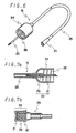
- Fig. 6 is a perspective view of an embodiment of an injection needle of the present invention having a female screw as a connecting means.
- Fig. 7a is a partially longitudinal sectional view of the injection needle of Fig. 6, and
- Fig. 7b is a partially longitudinal sectional view of an infusion tube to be connected to the injection needle of Fig. 6.
- an injection needle N of the present invention is characterized in that, in an injection needle having a tube 23 connected to the free end of a hub 22, a connecting means is provided at the hub 22.
- the injection needle N can be airtightly connected to an infusion tube 28 having, on the outer wall of an injection site 23 or on the external wall of the tubular body near the injection site 23, an connecting means 29 shown in Fig. 7b of which shape corresponds to that of the connecting means 24 of Fig. 7a.
- the infusion needle N and the infusion tube can be airtightly and securely connected to each other by sticking a needle 20 of the injection needle N into a rubber plug 31 of the injection site 23 of the infusion tube 28 to make the injection needle N communicate with the infusion tube 28 and then by combining both connecting means.
- the needle 20 comprises a canula 21 and a hub 22.
- the needle 20 is sticked into the rubber plug 31 of the infusion tube 28 having an injection site 23 at its connection end and serves to make the injection needle N communicate with the infusion tube 28.
- Material for the canula 21 and hub 22, and method of adhering them to each other to fabricate a needle 20 are not particularly limited in the present invention. Conventional material and method can be employed.
- a tube 23 is generally made of soft synthetic resin such as soft vinyl chloride resin and polyethylene.
- the tube 23 is connected to a free end (an end opposite the canula 21) of the hub 22 directly or through other suitable connecting means.
- the other end of the tube 23 is formed into suitable shapes depending on the purpose or condition of use. That is, a connecting means might be provided at the other end of the tube 23, or the other end might be formed to provide an infusion line.
- a connector 27 for connecting an infusion line and the like is provided at the other end of the tube 23.
- the connecting means 24 is provided at the hub 22. It is preferable that the connecting means 24 is so provided as to prevent the rotation of the needle 20 in the rubber plug 31 when the injection needle N is combined with the infusion tube 28 after the needle 20 is sticked into the rubber plug 31 of the injection site 23 of the infusion tube 28.
- a female screw 26 as a connecting means 24
- the female screw 26 is rotatably provided at the hub 22 (see Fig. 7a). In that case, it is necessary to employ a male screw 12 as a connecting means 29 of the infusion tube 28 for the rotatable female screw 26 (see Fig. 7b).
- the same material as in the connecting means and rubber plug of the connector described above can be employed.
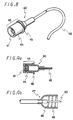
- Fig. 8 is a perspective view of an embodiment of an intravenous catheter of the present invention having a male screw as a connecting means.
- Fig. 9a is a partially longitudinal sectional view of the catheter of Fig. 8
- Fig. 9b is a partially longitudinal sectional view of an infusion line to be connected to the catheter of Fig. 8.
- a catheter of the present invention comprises a tubular connector 40 whereto a tube 42 of a small diameter is connected, characterized in that the connector 40 has an injection site 43, and a connecting means 44 is provided on the external wall of the injection site 43 or on the external wall of a tubular portion near the injection site 43.
- the connector 40 can be airtightly connected to an infusion line 47 shown in Fig. 9b having at its connection end a connecting means 49 of which shape corresponds to that of the connecting means 44 of Fig. 9a.
- the catheter and the infusion line 47 can be airtightly and securely connected to each other by sticking a needle 50 of the infusion line 47 into a rubber plug 41 of the injection site 43 of the catheter to make the catheter communicate with the infusion line 47 and then by combining both connecting means.
- the injection site 43 is used for infusing plural kinds of liquid drug into a patient by adding other liquid drugs from other infusion lines during fluid therapy.
- the injection site 43 comprises a tubular body having one or more fluid inlet and a fluid outlet.
- a cap or plug made of rubber-like elastic material is liquidtightly put on at least one fluid inlet. In the case of a cap, it is put on the fluid inlet, while in the case of a plug, it is inserted into the fluid inlet as shown in Fig. 9a.
- a means for supporting the cap or rubber plug 41 might be provided to prevent the detachment of the cap or rubber plug 41.
- the connecting means 44 functions also as a supporting means.
- the same material as in the cap or plug of the above-mentioned connector can be employed.
- the connecting means 44 serves to connect a catheter to a device to be connected (hereafter representatively referred to as infusion line), and the device has a needle at its connection end.
- the connecting means 44 alone does not function as a connector, but it cooperates with a connecting means 49 formed at the connection end of the infusion line 47 and combines the connector 40 with the infusion line 47.
- the shape of the connecting means 49 at the connection end of the infusion line 47 varies depending on the shape of the connecting means 44. That is, the shape of the connecting means 44 of the catheter and that of the connecting means 49 of the infusion line 47 are supplementary to each other. Such relationship is found in, for example, a male screw 45 in Fig. 9a and a female screw 46 in Fig. 9b.
- the connecting means 44 is provided on the external wall of the injection site 43 or on the external wall of a tubular portion near the injection site 43. It is preferable that the connecting means 44 is so provided as to prevent the rotation of the needle in the rubber plug 41 when the connector of the catheter and the infusion line 47 is connected to each other after a needle 10 of the infusion line 47 is sticked into the rubber plug 41 of the injection site 43.
- the male screw 45 is preferably fixed to the connector 40, i.e. adhered to or formed integrally with the connector 40, when the connecting means 4 comprises the male screw 45 (see Fig. 9a). In that case, it is necessary to employ, as a connecting means 49 of the infusion line 47, a rotatable female screw 46 for a fixed male screw 45 (see Fig. 9b).
- a tube 42 is a main portion of the catheter. In use, an free end of the tube 42 is remained in vein of a patient. Fluid therapy is carried out by infusing liquid drug and the like into vein through the injection site 43.
- material for the tube 42 soft sythetic resin can be employed, and the material is required to have bio-compatibility. Concrete examples of the preferably used material are, for example, vinyl chloride resin, polyurethane, and silicone rubber.
- a needle 50 of the infusion line 47 having a female screw 46 as a connecting means 49 as shown in Fig. 9b is sticked into a rubber plug 41 of an injection site 43 of the catheter. Then the rotation of the connecting means 49 of the infusion line 47 with one hand in the direction in which the connecting means 49 is screwed, while holding the catheter with other hand, gives the firm connection between the infusion line 47 and the catheter without causing the rotation of the needle 50 in the rubber plug 41.
- Fig. 10 is a perspective view of an embodiment of an infusion tube of the present invention having a male screw as a connecting means.
- Fig. 11 is a partially longitudinal sectional view of the infusion tube of Fig. 10
- Fig. 12 is a partially longitudinal sectional view of another embodiment of an infusion tube of the present invention.
- an infusion tube of the present invention comprises a spike needle or piercing spike (hereafter referred to as spike) 60, a drip chamber 62, an injection site 63, a flow-controlling means (a roller minicramp 66 is employed in Fig. 10), and an intravenous needle 67, and is characterized in that the injection site 63 is provided at a diverged tube of a tubular body (a Y-shaped tube 65 is employed in Fig. 10), and that a connecting means 64 is provided on the external wall of the injection site 43 or on the external wall of a tubular portion near the injection site 63.
- the connecting means 64 can be airtightly connected to an infusion line shown in Figs. 9b and 3b having at its connection end a connecting means of which shape corresponds to that of the connecting means of Fig. 11 or Fig. 12. That is, in the case of an infusion line of Fig. 9b, the infusion tube and the infusion line 47 can be airtightly and securely connected to each other by sticking a needle 50 of the infusion line 47 into the injection site 63 of the infusion line to make the infusion tube communicate with the infusion line 97 and then by combining both connecting means 64, 49.
- the spike 60, drip chamber 62, Y-shaped tube 65 and intravenous needle 67 are connected to one another by means of, for example, a tube made of soft vinyl chloride resin, and constitutes an infusion line.
- the roller cramp 66 is provided between the Y-shaped tube 65 and intravenous needle 67.
- the spike 60 is sticked into a plug of a container such as a bag in order to flow liquid drug and the like in the container into an infusion tube.
- the drip chamber 62 is used to monitor the priming of liquid drug and the like into the infusion tube and drip rate of liquid drug and the like flown.
- the Y-shaped tube 65 is a tubular body having a diverged route for introducing liquid drug and the like from other infusion routes.
- the intravenous needle 67 is sticked into vein of a patient to infuse liquid drug and the like into the vein of the patient.
- the injection site 63 is used for infusing plural kinds of liquid drug into a patient by adding other liquid drugs from other infusion lines during fluid therapy.
- the injection site 63 comprises a tubular body having one or more fluid inlet and a fluid outlet.
- a cap or plug made of rubber-like elastic material is liquidtightly put on at least one fluid inlet. In the case of a cap, it is put on the diverged route, while in the case of a plug, it is inserted into the diverged route.
- a means for supporting the cap or rubber plug 61 might be provided to prevent the detachment of the cap or rubber plug 61.
- the connecting means 64 functions also as a supporting means.
- the same material as in the cap or plug of the above-mentioned connector can be employed.
- the connecting means 64 serves to connect an infusion tube to an infusion line having a needle at its connection end.
- the connecting means 64 alone does not function as a connector, but it cooperates with a connecting means 49 formed at the connection end of the infusion line and combines the infusion tube with the infusion line. Accordingly the shape of the connecting means at the connection end of the infusion line varies depending on the shape of the connecting means 44. That is, the shape of the connecting means 44 of the infusion tube and that of the connecting means 49 of the infusion line 8 are supplementary to each other. Such relationship is found in, for example, a male screw 69 in Fig. 11 and a female screw 46 in Fig. 9b, or a female screw 70 in Fig. 12 and a male screw 13 in Fig. 3b.
- the connecting means 64 is provided on the external wall of the injection site 63 or on the external wall of a tubular portion near the injection site 63. It is preferable that the connecting means 64 is so provided as to prevent the rotation of the needle in the rubber plug 61 when the infusion tube and the infusion line is connected to each other after a needle of the infusion line 47 is sticked into the rubber plug 61 of the injection site 63.
- the male screw 69 is preferably fixed to the injection site 63 or the diverged route near the injection site 63, when the connecting means 64 comprises the male screw 69 (see Fig. 11).
- tubular body having a diverged route various kinds of tubular bodies such as T-shaped tube, crossed tube and tube having a plurality of diverged routes are employable beside the Y-shaped tube 65.
- tubular bodies such as T-shaped tube, crossed tube and tube having a plurality of diverged routes are employable beside the Y-shaped tube 65.
- a Y-shaped tube or T-shaped tube is generally employed.
- a needle 50 of the infusion line 47 having a female screw 46 as a connecting means 49 as shown in Fig. 9b is sticked into a rubber plug 61 of an injection site 63 of the infusion tube. Then the rotation of the connecting means 49 of the infusion line 47 with one hand in the direction in which the connecting means 49 is screwed, while holding the infusion tube with other hand, gives the firm connection between the infusion line 47 and the infusion tube without causing the rotation of the needle 50 in the rubber plug 61.
- the connector of the present invention is applicable to other devices such as blood circuit and solution infusion device besides an infusion needle, intravenous catheter and infusion tube explained hereinbefore.
- male screws and female screws are employed in the above explanations for an injection needle, intravenous catheter and infusion tube, pin-shaped or stake-shaped projections are off course employable.
Abstract
Description
- The present invention relates to a connector with an injection site and applications thereof, and more particularly to a connector with an injection site and applications thereof capable of, when injusing other liquid drug or nutrient fluid together with liquid drug or nutrient fluid to be infused during fluid therapy such as total parenteral nutrition or intravenous hyper alimentation, infusing liquid drug and/or nutrient fluid (hereafter referred to as liquid drug and the like) from another infusion line through an injection site by providing the injection site at a midway of the infusion line; and capable of, when infusing plural kinds of liquid drug and the like using the same intravenous catheter, infusing plural kinds of liquid drug and the like in order through an injection site by providing the injection site at a proximal portion of the intravenous catheter, i.e. at an introducing portion of liquid drug and the like.
- When infusing some liquid drug and the like together with other liquid drug and the like to be infused during fluid therapy such as total parenteral nutrition, there are usually used a solution infusion set or catheter (hereafter referred to as infusion tube) having a part called "injection site" at a midway of the infusion route. The other liquid drug and the like can be infused by sticking a needle of other infusion line into a rubber plug in the injection site of the infusion tube and by making the infusion tube communicate with the other infusion line.
- In the fluid therapy using an infusion line comprising an infusion tube and an intravenous catheter connected to the infusion tube, the solution infusion is sometimes interrupted for a long period of time. In that case, the infusion tube is detached from the intravenous catheter and a cap with a rubber plug called "injection plug" is put on the proximal portion of the intravenous catheter (a portion to be connected to the infusion tube). When the temporal solution infusion is required during interruption of a solution infusion, a needle of other infusion line is sticked into the rubber plug of the injection plug to make the intravenous catheter communicate with the other infusion line and to infuse solution.
- In the conventional infusion line using an injection site or an injection plug, however, a needle sometimes pulls out from the rubber plug when a patient under fluid therapy moves or touches the infusion line, since the needle is merely sticked into the rubber plug in the injection site or injection plug. Further there is a danger of infection from the air since a part of the needle is exposed to the air.
- The present invention was made to solve the above-mentioned problems, and it is an object of the present invention to provide a connector with an injection site which can prevent the pulling out of a needle of the other infusion line during fluid therapy, isolate the needle from the air to prevent the invasion of bacteria from the injection site.
- In accordance with the present invention, there is provided a connector with an injection site comprising a tubular body having one or more fluid inlet and a fluid outlet, wherein a cap or plug made of rubber-like elastic material is fit into at least one fluid inlet to form an injection site, and a connecting means is provided on the external wall of the injection site or on the external wall of the tubular body near the injection site.
- The connector with an injection site of the present invention has a connecting means on the external wall of the injection site or on the external wall of the tubular body near the injection site. Accodingly, when a needle of a device to be connected to the connector, for example, the needle of an infusion line having on the side of the needle a connecting means corresponding to the connecting means of the connector with the injection site is sticked into, for example, a rubber plug of the injection site of the connector, and the connecting means of the connector and that of the infusion line is connected to each other, the firm connection can be obtained.
- Further when the connecting means of the connector and that of the infusion line are so designed as to provide an airtight connection, infection from the air can be certainly prevented since the needle of the infusion line is isolated from the air and the needle is not pulled out from the rubber plug of the injection site during the use of infusion line.
- Fig. 1 is a perspective view of an embodiment of a connector of the present invention;
- Fig. 2a is a sectional view taken along the line X-X of Fig. 1;
- Fig. 2b is a partially explanatory view showing a connention end of an infusion line to be connected to the connector shown in Fig. 2a;
- Figs. 3a, 4a and 5a are partially sectional views of other embodiments of a connector of the present invention;
- Figs. 3b, 4b and 5b are respectively partially sectional views showing connection ends of infusion lines to be connected to the connectors shown in Figs. 3a, 4a and 5a;
- Fig. 6 is a perspective view of an embodiment of an injection needle of the present invention;
- Fig. 7a is a partially longitudinal sectional view of the injection needle of Fig. 6;
- Fig. 7b is a partially longitudinal sectional view of an infusion tube to be connected to the injection needle of Fig. 7a;
- Fig. 8 is a perspective view of an embodiment of an intravenous catheter of the present invention;
- Fig. 9a is a partially longitudinal sectional view of the intravenous catheter of Fig. 8;
- Fig. 9b is a partially longitudinal sectional view of an infusion tube to be connected to the intravenous catheter of Fig. 8;
- Fig. 10 is a schematic view of an embodiment of an infusion tube of the present invention;
- Fig. 11 is a partially longitudinal sectional view of the infusion tube of Fig. 10; and
- Fig. 12 is a partially longitudinal sectional view of another embodiment of an infusion tube of the present invention.
- Referring now to the accompanying drawings a connector of the present invention is explained.
- Fig. 1 is a perspective view of an embodiment of a connector of the present invention. The connector of Fig. 1 has a male screw as a connecting means and a connecting means comprising a female screw is provided at a fluid outlet.
- Fig. 2a is a sectional view taken along the line X-X of Fig. 1. Figs. 3a, 4a and 5a are partially sectional views of other embodiments of a connector of the present invention, and Figs. 3b, 4b and 5b are respectively partially secional views showing connection ends of infusion lines to be connected to the connectors shown in Figs. 3a, 4a and 5a.
- As shown in Figs. 1, 2a, 3a, 4a and 5a, a connector C of the present invention is a tubular connector having an
injection site 3, and characterized in that a connecting means is provided on the external wall of theinjection site 3 or on the external wall of the tubular body near theinjection site 3. The connector C can be airtightly connected to aninfusion line 8 having at its connection end aconnecting means 9 of which shape corresponds to that of theconnecting means 4 of Fig. 2a, Fig. 3a, Fig. 4a or Fig. 5a, as shown in Figs. 2b, 3b, 4b and 5b. That is, the connector C and theinfusion line 8 can be airtightly and firmly connected to each other by sticking aneedle 10 of theinfusion line 8 into theinjection site 3 of the connector to make the connector C communicate with theinfusion line 8 and then by combining both connecting means. - The connector of the present invention is hereinafter explained in detail mainly based on Figs. 1 and 2a.
- The
injection site 3 is used for infusing plural kinds of liquid drug into a patient by adding other liquid drugs from other infusion lines during fluid therapy. Theinjection site 3 comprises a tubular body (a part of the connector C excepting connecting means 4 and 6) having one ormore fluid inlet 2 and afluid outlet 5. A cap or plug made of rubber-like elastic material is liquidtightly put on at least onefluid inlet 2. In the case of a cap, it is put on thefluid inlet 2, while in the case of a plug, it is inserted into thefluid inlet 2 as shown in Fig. 2a. In that case, a means for supporting the cap orrubber plug 1 might be provided to prevent the detachment of the cap orrubber plug 1. In Fig. 2a, the connecting means 4 comprises a tubular portion functioning as a supporting means, and amale screw 7. - As described above the cap or plug is made of rubber-like elastic material. Concrete examples of the rubber-like elastic material are, for instance, natural rubber and synthetic rubber such as butadiene rubber, styrene-butadiene rubber, isoprene rubber, ethylene-propylene rubber, butyl rubber, chloroprene rubber, nitrile rubber, acrylic rubber, urethane rubber and silicone rubber. Among them, in particular, natural rubber, isoprene rubber, chloroprene rubber and silicone rubber are preferably used since they have small sticking resistance and good sealing property.
- The connecting means 4 on the side of the
fluid inlet 2 serves to connect the connector C to a device having a needle at its one end (hereafter representatively referred to as infusion line). The connecting means 4 alone does not function as a connector, but it cooperates with a connectingmeans 9 formed at the connecting end of theinfusion line 8 and combines the connector with the infusion line. Accordingly the shape of the connectingmeans 9 at the connection end of theinfusion line 8 varies depending on the shape of the connectingmeans 4. That is, the shape of the connectingmeans 4 of the connector C and that of the connectingmeans 9 of theinfusion line 8 are supplementary to each other. Such relationship is found in, for example, amale screw 7 in Fig. 2a and afemale screw 11 in Fig. 2b; afemale screw 12 in Fig. 3a and a male screw 13 in Fig. 3b; aprojection 14 in Fig. 4a and aslit 15 in Fig. 4b; and aslit 16 in Fig. 5a and aprojection 17 in Fig. 5b. The connecting means 4 might be composed solely of a male screw or a female screw, or might be composed of a tubular portion, and a male screw or a female screw as shown in Figs. 2a and 3a. - The connecting means 4 is provided on the external wall of the
injection site 3 or on the external wall of a tubular portion near theinjection site 3. When the connector C and theinfusion line 8 is connected to each other after aneedle 10 of theinfusion line 8 is sticked into theplug 1 of theinjection site 3, it is preferable that the connectingmeans 4 is so provided as to prevent the rotation of the needle in therubber plug 1. Concretely speaking, themale screw 7 is preferably fixed to the connector C, i.e. adhered to or formed integrally with the connector C, when the connectingmeans 4 comprises the male screw 7 (see Fig. 2a). When the connectingmeans 4 comprises thefemale screw 12, it is preferable that thefemale screw 12 is rotatably provided at the connector C (see Fig. 3a). Further, when the connectingmeans 4 comprises aprojection 14 or aslit 16, theprojection 14 or slit 16 might be fixedly or rotatably provided at the connector (see Figs. 4a and 5a). In that case, it is necessary to employ, as a connectingmeans 9 of aninfusion line 8, a rotatablefemale screw 11 for a fixedmale screw 7; a fixed male screw 13 for a rotatablefemale screw 12; arotatable slit 15 orprojection 17 for a fixedprojection 14 or slit 16; a fixedslit 15 orprojection 17 for arotatable projection 14 or slit 16 (see Figs. 2b, 3b, 4b and 5b). - A connecting means 6 on the side of the
fluid outlet 5 is optionally employed, and therefore is not always necessary. The opening end of a tube might be directly inserted into thefluid outlet 5 and, if necessary, adhered thereto by means of adhesives and the like. In the case where the tube cannot be firmly connected to the connector C for reason of material, however, it is necessary to provide a connecting means 6 at thefluid outlet 5. By means of the connecting means 6, a tube having at its connection end a supplemental connecting means with the connecting means 6, for example, an intravenous catheter can be surely and securely connected to the connector. - As a material for a tubular portion of the connector C, it is preferable to employ sythetic resin having a resistance to liquid drug used as a solution for infusion. There can be preferably used, for example, polyethylene, polypropylene, hard vinyl chloride resin, acrylonitrile-butadiene-styrene copolymer, or styrene-acrylonitrile copolymer. Material for the connecting
means 4 and 6 is not particularly limited in the present invention. Synthetic resin is generally employable, and polystyrene, polyamide, polyester, polycarbonate and polymethyl methacrylate can be preferably employed besides the materials described above as a material for the tubular portion of the connector. - Next a method of using a connector C of the present invention is explained.
- In the case of a connector C shown in Fig. 2a having a
male screw 7 as a connectingmeans 4, aneedle 10 of theinfusion line 8 having afemale screw 11 as a connecting means as shown in Fig. 2b is sticked into arubber plug 1 of aninjection site 3 of the connector C. Then the rotation of the connectingmeans 9 of theinfusion line 8 with one hand in the direction in which the connectingmeans 9 is screwed, while holding the connector C with other hand, gives the firm connection between theinfusion line 8 and the connector C without causing the rotation of theneedle 10 in therubber plug 1. - In the case of a connector C having a
projection 14 as a connectingmeans 4 as shown in Fig. 4a, aneedle 10 of theinfusion line 8 having aslit 15 as a connecting means as shown in Fig. 4b is sticked into arubber plug 1 of aninjection site 3 of the connector C. Then the rotation of the connectingmeans 9 of theinfusion line 8 with one hand and the insertion of the projection into theslit 15, while holding the connector C with other hand, gives the firm connection between theinfusion line 8 and the connector C. - Explanations for the combination of a connector C of Fig. 3a and an infusion line of Fig. 3b, and the combination of a connector C of Fig. 5a and an infusion line of Fig. 5b are omitted since they correspond respectively to those for the combination of a connector C of Fig. 2a and an infusion line of Fig. 2b, and the combination of a connector C of Fig. 4a and an infusion line of Fig. 4b.
- Next there are explained in order three embodiments of an injection needle, an intravenous catheter, and an infusion tube which all adapt a connector of the present invention or its conception.
- Fig. 6 is a perspective view of an embodiment of an injection needle of the present invention having a female screw as a connecting means. Fig. 7a is a partially longitudinal sectional view of the injection needle of Fig. 6, and Fig. 7b is a partially longitudinal sectional view of an infusion tube to be connected to the injection needle of Fig. 6.
- As shown in Figs. 6 and 7a, an injection needle N of the present invention is characterized in that, in an injection needle having a
tube 23 connected to the free end of ahub 22, a connecting means is provided at thehub 22. The injection needle N can be airtightly connected to aninfusion tube 28 having, on the outer wall of aninjection site 23 or on the external wall of the tubular body near theinjection site 23, an connectingmeans 29 shown in Fig. 7b of which shape corresponds to that of the connecting means 24 of Fig. 7a. That is, the infusion needle N and the infusion tube can be airtightly and securely connected to each other by sticking aneedle 20 of the injection needle N into arubber plug 31 of theinjection site 23 of theinfusion tube 28 to make the injection needle N communicate with theinfusion tube 28 and then by combining both connecting means. - The
needle 20 comprises acanula 21 and ahub 22. In use, theneedle 20 is sticked into therubber plug 31 of theinfusion tube 28 having aninjection site 23 at its connection end and serves to make the injection needle N communicate with theinfusion tube 28. - Material for the
canula 21 andhub 22, and method of adhering them to each other to fabricate aneedle 20 are not particularly limited in the present invention. Conventional material and method can be employed. - A
tube 23 is generally made of soft synthetic resin such as soft vinyl chloride resin and polyethylene. Thetube 23 is connected to a free end (an end opposite the canula 21) of thehub 22 directly or through other suitable connecting means. The other end of thetube 23 is formed into suitable shapes depending on the purpose or condition of use. That is, a connecting means might be provided at the other end of thetube 23, or the other end might be formed to provide an infusion line. In Fig. 6, aconnector 27 for connecting an infusion line and the like is provided at the other end of thetube 23. - The connecting means 24 is provided at the
hub 22. It is preferable that the connectingmeans 24 is so provided as to prevent the rotation of theneedle 20 in therubber plug 31 when the injection needle N is combined with theinfusion tube 28 after theneedle 20 is sticked into therubber plug 31 of theinjection site 23 of theinfusion tube 28. For example, when employing afemale screw 26 as a connectingmeans 24, it is preferable that thefemale screw 26 is rotatably provided at the hub 22 (see Fig. 7a). In that case, it is necessary to employ amale screw 12 as a connectingmeans 29 of theinfusion tube 28 for the rotatable female screw 26 (see Fig. 7b). - As a material for the connecting
means rubber plug 31, the same material as in the connecting means and rubber plug of the connector described above can be employed. - A method of using an injection needle N of the present invention is explained.
- In the case of an injection needle N shown in Fig. 7a having a
female screw 26 as a connecing means 24, aneedle 20 of the injection needle N is sticked into arubber plug 31 of theinjection site 23 of theinfusion tube 28 having amale screw 32 as a connectingmeans 29 as shown in Fig. 7b. Then the rotation of the connecting means 24 of the injection needle N with one hand in the direction in which the connectingmeans 24 is screwed, while holding theinfusion tube 28 with other hand, gives the firm connection between the injection needle N and theinfusion tube 28. - Next an intravenous catheter adapting a connector of the present invention is explained.
- Fig. 8 is a perspective view of an embodiment of an intravenous catheter of the present invention having a male screw as a connecting means. Fig. 9a is a partially longitudinal sectional view of the catheter of Fig. 8, and Fig. 9b is a partially longitudinal sectional view of an infusion line to be connected to the catheter of Fig. 8.
- As shown in Figs. 8 and 9a, a catheter of the present invention comprises a
tubular connector 40 whereto atube 42 of a small diameter is connected, characterized in that theconnector 40 has aninjection site 43, and a connectingmeans 44 is provided on the external wall of theinjection site 43 or on the external wall of a tubular portion near theinjection site 43. Theconnector 40 can be airtightly connected to aninfusion line 47 shown in Fig. 9b having at its connection end a connectingmeans 49 of which shape corresponds to that of the connecting means 44 of Fig. 9a. That is, the catheter and theinfusion line 47 can be airtightly and securely connected to each other by sticking aneedle 50 of theinfusion line 47 into arubber plug 41 of theinjection site 43 of the catheter to make the catheter communicate with theinfusion line 47 and then by combining both connecting means. - The
injection site 43 is used for infusing plural kinds of liquid drug into a patient by adding other liquid drugs from other infusion lines during fluid therapy. Theinjection site 43 comprises a tubular body having one or more fluid inlet and a fluid outlet. A cap or plug made of rubber-like elastic material is liquidtightly put on at least one fluid inlet. In the case of a cap, it is put on the fluid inlet, while in the case of a plug, it is inserted into the fluid inlet as shown in Fig. 9a. In that case, a means for supporting the cap orrubber plug 41 might be provided to prevent the detachment of the cap orrubber plug 41. In Fig. 9a, the connecting means 44 functions also as a supporting means. - As a material for the cap or plug, the same material as in the cap or plug of the above-mentioned connector can be employed.
- The connecting means 44 serves to connect a catheter to a device to be connected (hereafter representatively referred to as infusion line), and the device has a needle at its connection end. The connecting means 44 alone does not function as a connector, but it cooperates with a connecting
means 49 formed at the connection end of theinfusion line 47 and combines theconnector 40 with theinfusion line 47. Accordingly the shape of the connecting means 49 at the connection end of theinfusion line 47 varies depending on the shape of the connectingmeans 44. That is, the shape of the connecting means 44 of the catheter and that of the connecting means 49 of theinfusion line 47 are supplementary to each other. Such relationship is found in, for example, amale screw 45 in Fig. 9a and afemale screw 46 in Fig. 9b. - The connecting means 44 is provided on the external wall of the
injection site 43 or on the external wall of a tubular portion near theinjection site 43. It is preferable that the connectingmeans 44 is so provided as to prevent the rotation of the needle in therubber plug 41 when the connector of the catheter and theinfusion line 47 is connected to each other after aneedle 10 of theinfusion line 47 is sticked into therubber plug 41 of theinjection site 43. Concretely speaking, themale screw 45 is preferably fixed to theconnector 40, i.e. adhered to or formed integrally with theconnector 40, when the connectingmeans 4 comprises the male screw 45 (see Fig. 9a). In that case, it is necessary to employ, as a connectingmeans 49 of theinfusion line 47, a rotatablefemale screw 46 for a fixed male screw 45 (see Fig. 9b). - A
tube 42 is a main portion of the catheter. In use, an free end of thetube 42 is remained in vein of a patient. Fluid therapy is carried out by infusing liquid drug and the like into vein through theinjection site 43. As material for thetube 42, soft sythetic resin can be employed, and the material is required to have bio-compatibility. Concrete examples of the preferably used material are, for example, vinyl chloride resin, polyurethane, and silicone rubber. - Next a method of using an intravenous catheter of the present invention is explained.
- In the case of a catheter shown in Fig. 9a having a
male screw 45 as a connectingmeans 44, aneedle 50 of theinfusion line 47 having afemale screw 46 as a connectingmeans 49 as shown in Fig. 9b is sticked into arubber plug 41 of aninjection site 43 of the catheter. Then the rotation of the connecting means 49 of theinfusion line 47 with one hand in the direction in which the connectingmeans 49 is screwed, while holding the catheter with other hand, gives the firm connection between theinfusion line 47 and the catheter without causing the rotation of theneedle 50 in therubber plug 41. - Finally an infusion tube adapting a connector of the present invention is explained.
- Fig. 10 is a perspective view of an embodiment of an infusion tube of the present invention having a male screw as a connecting means. Fig. 11 is a partially longitudinal sectional view of the infusion tube of Fig. 10, and Fig. 12 is a partially longitudinal sectional view of another embodiment of an infusion tube of the present invention.
- As shown in Figs. 10 to 12, an infusion tube of the present invention comprises a spike needle or piercing spike (hereafter referred to as spike) 60, a
drip chamber 62, aninjection site 63, a flow-controlling means (aroller minicramp 66 is employed in Fig. 10), and anintravenous needle 67, and is characterized in that theinjection site 63 is provided at a diverged tube of a tubular body (a Y-shapedtube 65 is employed in Fig. 10), and that a connectingmeans 64 is provided on the external wall of theinjection site 43 or on the external wall of a tubular portion near theinjection site 63. - The connecting means 64 can be airtightly connected to an infusion line shown in Figs. 9b and 3b having at its connection end a connecting means of which shape corresponds to that of the connecting means of Fig. 11 or Fig. 12. That is, in the case of an infusion line of Fig. 9b, the infusion tube and the
infusion line 47 can be airtightly and securely connected to each other by sticking aneedle 50 of theinfusion line 47 into theinjection site 63 of the infusion line to make the infusion tube communicate with the infusion line 97 and then by combining both connectingmeans - The
spike 60,drip chamber 62, Y-shapedtube 65 andintravenous needle 67 are connected to one another by means of, for example, a tube made of soft vinyl chloride resin, and constitutes an infusion line. Theroller cramp 66 is provided between the Y-shapedtube 65 andintravenous needle 67. - The
spike 60 is sticked into a plug of a container such as a bag in order to flow liquid drug and the like in the container into an infusion tube. Thedrip chamber 62 is used to monitor the priming of liquid drug and the like into the infusion tube and drip rate of liquid drug and the like flown. The Y-shapedtube 65 is a tubular body having a diverged route for introducing liquid drug and the like from other infusion routes. Theintravenous needle 67 is sticked into vein of a patient to infuse liquid drug and the like into the vein of the patient. - The
injection site 63 is used for infusing plural kinds of liquid drug into a patient by adding other liquid drugs from other infusion lines during fluid therapy. Theinjection site 63 comprises a tubular body having one or more fluid inlet and a fluid outlet. A cap or plug made of rubber-like elastic material is liquidtightly put on at least one fluid inlet. In the case of a cap, it is put on the diverged route, while in the case of a plug, it is inserted into the diverged route. In that case, a means for supporting the cap orrubber plug 61 might be provided to prevent the detachment of the cap orrubber plug 61. In Fig. 11, the connecting means 64 functions also as a supporting means. - As a material for the cap or plug, the same material as in the cap or plug of the above-mentioned connector can be employed.
- The connecting means 64 serves to connect an infusion tube to an infusion line having a needle at its connection end.
- The connecting means 64 alone does not function as a connector, but it cooperates with a connecting
means 49 formed at the connection end of the infusion line and combines the infusion tube with the infusion line. Accordingly the shape of the connecting means at the connection end of the infusion line varies depending on the shape of the connectingmeans 44. That is, the shape of the connecting means 44 of the infusion tube and that of the connecting means 49 of theinfusion line 8 are supplementary to each other. Such relationship is found in, for example, amale screw 69 in Fig. 11 and afemale screw 46 in Fig. 9b, or afemale screw 70 in Fig. 12 and a male screw 13 in Fig. 3b. The connecting means 64 is provided on the external wall of theinjection site 63 or on the external wall of a tubular portion near theinjection site 63. It is preferable that the connectingmeans 64 is so provided as to prevent the rotation of the needle in therubber plug 61 when the infusion tube and the infusion line is connected to each other after a needle of theinfusion line 47 is sticked into therubber plug 61 of theinjection site 63. Concretely speaking, themale screw 69 is preferably fixed to theinjection site 63 or the diverged route near theinjection site 63, when the connectingmeans 64 comprises the male screw 69 (see Fig. 11). In that case, it is necessary to employ, as a connectingmeans 49 of aninfusion line 47, a rotatablefemale screw 46 for a fixedmale screw 69 of the infusion tube (see Fig. 9b), and a fixed male screw 13 for a rotatablefemale screw 70 of the infusion tube (see Fig. 3b). - As a tubular body having a diverged route, various kinds of tubular bodies such as T-shaped tube, crossed tube and tube having a plurality of diverged routes are employable beside the Y-shaped
tube 65. Among them, a Y-shaped tube or T-shaped tube is generally employed. - Next a method of using infusion tube of the present invention is explained.
- In the case of a infusion tube shown in Fig. 11 having a
male screw 69 as a connectingmeans 64, aneedle 50 of theinfusion line 47 having afemale screw 46 as a connectingmeans 49 as shown in Fig. 9b is sticked into arubber plug 61 of aninjection site 63 of the infusion tube. Then the rotation of the connecting means 49 of theinfusion line 47 with one hand in the direction in which the connectingmeans 49 is screwed, while holding the infusion tube with other hand, gives the firm connection between theinfusion line 47 and the infusion tube without causing the rotation of theneedle 50 in therubber plug 61. - The connector of the present invention is applicable to other devices such as blood circuit and solution infusion device besides an infusion needle, intravenous catheter and infusion tube explained hereinbefore. Though male screws and female screws are employed in the above explanations for an injection needle, intravenous catheter and infusion tube, pin-shaped or stake-shaped projections are off course employable.
- As is clear from the above explanation, the following effects can be obtained by the use of a connector of the present invention.
- (1) Sheets or clothes of a patient is not soiled with liquid drug since the needle of an infusion line is not pulled out during treatment.
- (2) Infection by the air through an injection site can be perfectly avoided by the structure enabling airtight connection.
Claims (17)
Applications Claiming Priority (4)
| Application Number | Priority Date | Filing Date | Title |
|---|---|---|---|
| JP308860/87 | 1987-12-07 | ||
| JP186267/87U | 1987-12-07 | ||
| JP62308860A JPH0626586B2 (en) | 1987-12-07 | 1987-12-07 | Connection part with mixed injection part |
| JP18626787U JPH0190550U (en) | 1987-12-07 | 1987-12-07 |
Publications (3)
| Publication Number | Publication Date |
|---|---|
| EP0319764A2 true EP0319764A2 (en) | 1989-06-14 |
| EP0319764A3 EP0319764A3 (en) | 1992-09-02 |
| EP0319764B1 EP0319764B1 (en) | 1995-08-30 |
Family
ID=26503648
Family Applications (1)
| Application Number | Title | Priority Date | Filing Date |
|---|---|---|---|
| EP88119376A Expired - Lifetime EP0319764B1 (en) | 1987-12-07 | 1988-11-22 | Connector with injection site |
Country Status (3)
| Country | Link |
|---|---|
| EP (1) | EP0319764B1 (en) |
| DE (1) | DE3854379T2 (en) |
| IT (1) | IT1227506B (en) |
Cited By (12)
| Publication number | Priority date | Publication date | Assignee | Title |
|---|---|---|---|---|
| WO1991005581A1 (en) * | 1989-10-23 | 1991-05-02 | Baxter International Inc. | Pre-slit injection site |
| WO1991007206A1 (en) * | 1989-11-09 | 1991-05-30 | Baxter International Inc. | Bayonet lock cannula for pre-slit y-site |
| EP0438909A1 (en) * | 1990-01-10 | 1991-07-31 | Vincent L. Vaillancourt | A needle connector |
| EP0512281A1 (en) * | 1991-05-02 | 1992-11-11 | Fresenius AG | Connector for a pharmaceutical solution container |
| EP0527951A1 (en) * | 1990-05-07 | 1993-02-24 | Ryan Medical Inc | Medical intravenous administration line connector. |
| US5290222A (en) * | 1991-10-15 | 1994-03-01 | Jiyu Feng | Injection port connector with rotatable locking lug |
| USRE35841E (en) * | 1990-09-18 | 1998-07-07 | Medex, Inc. | Needleless connector sample site |
| WO2001052925A1 (en) * | 2000-01-18 | 2001-07-26 | Sterling Medivations, Inc. | Pen needle assembly and adapter |
| US6497682B1 (en) * | 2000-08-14 | 2002-12-24 | Peter Quartararo | Infection preventing device, and an introducer provided therewith |
| GB2486652A (en) * | 2010-12-21 | 2012-06-27 | Peak Medical Ltd | Infusion catheter with a detachable needle |
| CN105327417A (en) * | 2015-11-20 | 2016-02-17 | 无锡顶点医疗器械有限公司 | Separator for insulin pump infusion pipe |
| CN114191651A (en) * | 2021-12-06 | 2022-03-18 | 西安市第一医院 | Connector anti-pulling type connected remaining needle |
Families Citing this family (8)
| Publication number | Priority date | Publication date | Assignee | Title |
|---|---|---|---|---|
| EP0544654B1 (en) | 1988-01-25 | 1994-12-07 | Baxter International Inc. | Blunt cannula device |
| US5964785A (en) | 1988-01-25 | 1999-10-12 | Baxter International Inc. | Bayonet look cannula for pre-slit y-site |
| CA1330412C (en) | 1988-07-08 | 1994-06-28 | Steven C. Jepson | Pre-slit injection site and tapered cannula |
| IE66526B1 (en) | 1989-03-17 | 1996-01-24 | Baxter Int | A pre-slit injection site usable with a blunt cannula |
| US5776125A (en) | 1991-07-30 | 1998-07-07 | Baxter International Inc. | Needleless vial access device |
| RU94030466A (en) | 1991-12-18 | 1996-05-20 | Айку Медикал Инк. (US) | Medical valve, method of medium transfusion, method of transfusion of predetermined amount of medicines |
| US5738663A (en) | 1995-12-15 | 1998-04-14 | Icu Medical, Inc. | Medical valve with fluid escape space |
| US6685674B2 (en) | 2001-03-04 | 2004-02-03 | Sterling Medivations, Inc. | Infusion hub assembly and fluid line disconnect system |
Citations (7)
| Publication number | Priority date | Publication date | Assignee | Title |
|---|---|---|---|---|
| FR1447174A (en) * | 1964-12-29 | 1966-07-29 | Stille Werner Ab | Cannula device |
| FR2322614A1 (en) * | 1975-09-02 | 1977-04-01 | Sandoz Sa | BLOOD ACCESS DEVICE FOR AN EXTRA-BODY BLOOD LINE |
| DE2720470A1 (en) * | 1976-05-06 | 1977-11-10 | Gist Brocades Nv | CATHETER DEVICE |
| CA1105959A (en) * | 1979-01-15 | 1981-07-28 | Dimitrios G. Oreopoulos | Connector |
| EP0114677A2 (en) * | 1983-01-24 | 1984-08-01 | ICU Medical, Inc. | Medical connector system |
| US4512766A (en) * | 1982-12-08 | 1985-04-23 | Whitman Medical Corporation | Catheter valve |
| US4673400A (en) * | 1986-02-10 | 1987-06-16 | Martin Ivan W | Aseptic connector assembly for conduits for sterile fluids |
-
1988
- 1988-11-22 EP EP88119376A patent/EP0319764B1/en not_active Expired - Lifetime
- 1988-11-22 DE DE3854379T patent/DE3854379T2/en not_active Expired - Fee Related
- 1988-12-06 IT IT8822874A patent/IT1227506B/en active
Patent Citations (7)
| Publication number | Priority date | Publication date | Assignee | Title |
|---|---|---|---|---|
| FR1447174A (en) * | 1964-12-29 | 1966-07-29 | Stille Werner Ab | Cannula device |
| FR2322614A1 (en) * | 1975-09-02 | 1977-04-01 | Sandoz Sa | BLOOD ACCESS DEVICE FOR AN EXTRA-BODY BLOOD LINE |
| DE2720470A1 (en) * | 1976-05-06 | 1977-11-10 | Gist Brocades Nv | CATHETER DEVICE |
| CA1105959A (en) * | 1979-01-15 | 1981-07-28 | Dimitrios G. Oreopoulos | Connector |
| US4512766A (en) * | 1982-12-08 | 1985-04-23 | Whitman Medical Corporation | Catheter valve |
| EP0114677A2 (en) * | 1983-01-24 | 1984-08-01 | ICU Medical, Inc. | Medical connector system |
| US4673400A (en) * | 1986-02-10 | 1987-06-16 | Martin Ivan W | Aseptic connector assembly for conduits for sterile fluids |
Cited By (18)
| Publication number | Priority date | Publication date | Assignee | Title |
|---|---|---|---|---|
| EP0567202A2 (en) * | 1989-10-23 | 1993-10-27 | Baxter International Inc. | Injection site |
| EP0567202A3 (en) * | 1989-10-23 | 1993-11-24 | Baxter Int | Injection site |
| WO1991005581A1 (en) * | 1989-10-23 | 1991-05-02 | Baxter International Inc. | Pre-slit injection site |
| WO1991007206A1 (en) * | 1989-11-09 | 1991-05-30 | Baxter International Inc. | Bayonet lock cannula for pre-slit y-site |
| EP0438909A1 (en) * | 1990-01-10 | 1991-07-31 | Vincent L. Vaillancourt | A needle connector |
| AU637442B2 (en) * | 1990-01-10 | 1993-05-27 | Vincent L. Vaillancourt | Needle connector |
| EP0527951A1 (en) * | 1990-05-07 | 1993-02-24 | Ryan Medical Inc | Medical intravenous administration line connector. |
| EP0527951A4 (en) * | 1990-05-07 | 1993-09-22 | Ryan Medical Inc. | Medical intravenous administration line connector |
| USRE35841E (en) * | 1990-09-18 | 1998-07-07 | Medex, Inc. | Needleless connector sample site |
| EP0512281A1 (en) * | 1991-05-02 | 1992-11-11 | Fresenius AG | Connector for a pharmaceutical solution container |
| US5290222A (en) * | 1991-10-15 | 1994-03-01 | Jiyu Feng | Injection port connector with rotatable locking lug |
| WO2001052925A1 (en) * | 2000-01-18 | 2001-07-26 | Sterling Medivations, Inc. | Pen needle assembly and adapter |
| US6497682B1 (en) * | 2000-08-14 | 2002-12-24 | Peter Quartararo | Infection preventing device, and an introducer provided therewith |
| GB2486652A (en) * | 2010-12-21 | 2012-06-27 | Peak Medical Ltd | Infusion catheter with a detachable needle |
| CN105327417A (en) * | 2015-11-20 | 2016-02-17 | 无锡顶点医疗器械有限公司 | Separator for insulin pump infusion pipe |
| CN105327417B (en) * | 2015-11-20 | 2019-12-31 | 无锡顶点医疗器械有限公司 | Separator for insulin pump infusion pipeline |
| CN114191651A (en) * | 2021-12-06 | 2022-03-18 | 西安市第一医院 | Connector anti-pulling type connected remaining needle |
| CN114191651B (en) * | 2021-12-06 | 2024-01-30 | 西安市第一医院 | Connector pulling-preventing type connected indwelling needle |
Also Published As
| Publication number | Publication date |
|---|---|
| EP0319764B1 (en) | 1995-08-30 |
| EP0319764A3 (en) | 1992-09-02 |
| DE3854379T2 (en) | 1996-03-21 |
| IT1227506B (en) | 1991-04-12 |
| DE3854379D1 (en) | 1995-10-05 |
| IT8822874A0 (en) | 1988-12-06 |
Similar Documents
| Publication | Publication Date | Title |
|---|---|---|
| US5334188A (en) | Connector with injection site | |
| EP0319764B1 (en) | Connector with injection site | |
| US8585655B2 (en) | Securement device for I.V. t-connector | |
| US20200360602A1 (en) | Infusion set for a fluid pump | |
| US4569675A (en) | Transcutaneous infusion system | |
| US7713246B2 (en) | Automatic valve | |
| US8551067B2 (en) | Needleless additive control valve | |
| US7316679B2 (en) | Medical device connector fitting | |
| US3942528A (en) | Non-kinking intravenous tube loop device | |
| US20060089604A1 (en) | Infusion device for administering fluids to a patient | |
| EP1790376A1 (en) | Single lumen adapter for automatic valve | |
| EP0038355A4 (en) | Breakaway valve. | |
| AU2002236837A1 (en) | Medical device connector fitting | |
| JPH11319114A (en) | Adapter | |
| KR960009419B1 (en) | Connector with injection site | |
| JP4066222B2 (en) | Connector with automatic opening / closing valve and medical device using the same | |
| JPH0492668A (en) | Nasal nutrition tube | |
| CN215275002U (en) | Infusion pipeline assembly and medical pipeline structure | |
| JP3525550B2 (en) | Fluid dosing or sampling device | |
| JPH065801Y2 (en) | Medical connection | |
| JP4087267B2 (en) | Indwelling catheter | |
| JP2003000726A (en) | Connector | |
| JPH0613850U (en) | IVH catheter with filter | |
| AU6488480A (en) | Breakaway valve |
Legal Events
| Date | Code | Title | Description |
|---|---|---|---|
| PUAI | Public reference made under article 153(3) epc to a published international application that has entered the european phase |
Free format text: ORIGINAL CODE: 0009012 |
|
| AK | Designated contracting states |
Kind code of ref document: A2 Designated state(s): BE DE FR GB NL SE |
|
| PUAL | Search report despatched |
Free format text: ORIGINAL CODE: 0009013 |
|
| AK | Designated contracting states |
Kind code of ref document: A3 Designated state(s): BE DE FR GB NL SE |
|
| 17P | Request for examination filed |
Effective date: 19921027 |
|
| 17Q | First examination report despatched |
Effective date: 19940603 |
|
| GRAA | (expected) grant |
Free format text: ORIGINAL CODE: 0009210 |
|
| AK | Designated contracting states |
Kind code of ref document: B1 Designated state(s): BE DE FR GB NL SE |
|
| REF | Corresponds to: |
Ref document number: 3854379 Country of ref document: DE Date of ref document: 19951005 |
|
| ET | Fr: translation filed | ||
| PLBE | No opposition filed within time limit |
Free format text: ORIGINAL CODE: 0009261 |
|
| STAA | Information on the status of an ep patent application or granted ep patent |
Free format text: STATUS: NO OPPOSITION FILED WITHIN TIME LIMIT |
|
| 26N | No opposition filed | ||
| REG | Reference to a national code |
Ref country code: GB Ref legal event code: IF02 |
|
| PGFP | Annual fee paid to national office [announced via postgrant information from national office to epo] |
Ref country code: SE Payment date: 20061106 Year of fee payment: 19 |
|
| PGFP | Annual fee paid to national office [announced via postgrant information from national office to epo] |
Ref country code: FR Payment date: 20061108 Year of fee payment: 19 |
|
| PGFP | Annual fee paid to national office [announced via postgrant information from national office to epo] |
Ref country code: NL Payment date: 20061115 Year of fee payment: 19 |
|
| PGFP | Annual fee paid to national office [announced via postgrant information from national office to epo] |
Ref country code: DE Payment date: 20061116 Year of fee payment: 19 |
|
| PGFP | Annual fee paid to national office [announced via postgrant information from national office to epo] |
Ref country code: GB Payment date: 20061122 Year of fee payment: 19 |
|
| PGFP | Annual fee paid to national office [announced via postgrant information from national office to epo] |
Ref country code: BE Payment date: 20070118 Year of fee payment: 19 |
|
| BERE | Be: lapsed |
Owner name: NISSHO CORP. Effective date: 20071130 |
|
| EUG | Se: european patent has lapsed | ||
| GBPC | Gb: european patent ceased through non-payment of renewal fee |
Effective date: 20071122 |
|
| NLV4 | Nl: lapsed or anulled due to non-payment of the annual fee |
Effective date: 20080601 |
|
| PG25 | Lapsed in a contracting state [announced via postgrant information from national office to epo] |
Ref country code: BE Free format text: LAPSE BECAUSE OF NON-PAYMENT OF DUE FEES Effective date: 20071130 |
|
| PG25 | Lapsed in a contracting state [announced via postgrant information from national office to epo] |
Ref country code: NL Free format text: LAPSE BECAUSE OF NON-PAYMENT OF DUE FEES Effective date: 20080601 Ref country code: SE Free format text: LAPSE BECAUSE OF NON-PAYMENT OF DUE FEES Effective date: 20071123 Ref country code: DE Free format text: LAPSE BECAUSE OF NON-PAYMENT OF DUE FEES Effective date: 20080603 |
|
| REG | Reference to a national code |
Ref country code: FR Ref legal event code: ST Effective date: 20080930 |
|
| PG25 | Lapsed in a contracting state [announced via postgrant information from national office to epo] |
Ref country code: GB Free format text: LAPSE BECAUSE OF NON-PAYMENT OF DUE FEES Effective date: 20071122 |
|
| PG25 | Lapsed in a contracting state [announced via postgrant information from national office to epo] |
Ref country code: FR Free format text: LAPSE BECAUSE OF NON-PAYMENT OF DUE FEES Effective date: 20071130 |