EP0319397B1 - Laser-Schock-Behandlungsverfahren von Materialien - Google Patents
Laser-Schock-Behandlungsverfahren von Materialien Download PDFInfo
- Publication number
- EP0319397B1 EP0319397B1 EP19880403000 EP88403000A EP0319397B1 EP 0319397 B1 EP0319397 B1 EP 0319397B1 EP 19880403000 EP19880403000 EP 19880403000 EP 88403000 A EP88403000 A EP 88403000A EP 0319397 B1 EP0319397 B1 EP 0319397B1
- Authority
- EP
- European Patent Office
- Prior art keywords
- laser
- pulse
- laser radiation
- thermal treatment
- contact
- Prior art date
- Legal status (The legal status is an assumption and is not a legal conclusion. Google has not performed a legal analysis and makes no representation as to the accuracy of the status listed.)
- Expired - Lifetime
Links
- 239000000463 material Substances 0.000 title claims description 24
- 238000002635 electroconvulsive therapy Methods 0.000 title claims description 3
- 238000000034 method Methods 0.000 claims description 24
- 230000005855 radiation Effects 0.000 claims description 18
- 239000007788 liquid Substances 0.000 claims description 9
- IJGRMHOSHXDMSA-UHFFFAOYSA-N Atomic nitrogen Chemical compound N#N IJGRMHOSHXDMSA-UHFFFAOYSA-N 0.000 claims description 8
- 230000004907 flux Effects 0.000 claims description 8
- 230000035939 shock Effects 0.000 claims description 6
- 239000012530 fluid Substances 0.000 claims description 5
- 229910052757 nitrogen Inorganic materials 0.000 claims description 4
- 239000007789 gas Substances 0.000 claims description 2
- 230000001678 irradiating effect Effects 0.000 claims description 2
- 238000007669 thermal treatment Methods 0.000 claims 5
- 230000002745 absorbent Effects 0.000 description 7
- 239000002250 absorbent Substances 0.000 description 7
- 238000010586 diagram Methods 0.000 description 5
- 230000000694 effects Effects 0.000 description 5
- 230000006835 compression Effects 0.000 description 4
- 238000007906 compression Methods 0.000 description 4
- 239000011521 glass Substances 0.000 description 4
- 238000010438 heat treatment Methods 0.000 description 4
- 230000000630 rising effect Effects 0.000 description 4
- 239000011248 coating agent Substances 0.000 description 3
- 238000000576 coating method Methods 0.000 description 3
- 239000012153 distilled water Substances 0.000 description 3
- 238000009434 installation Methods 0.000 description 3
- 229910052751 metal Inorganic materials 0.000 description 3
- 239000002184 metal Substances 0.000 description 3
- 239000003973 paint Substances 0.000 description 3
- 238000004381 surface treatment Methods 0.000 description 3
- 239000012780 transparent material Substances 0.000 description 3
- XLYOFNOQVPJJNP-UHFFFAOYSA-N water Chemical compound O XLYOFNOQVPJJNP-UHFFFAOYSA-N 0.000 description 3
- CURLTUGMZLYLDI-UHFFFAOYSA-N Carbon dioxide Chemical compound O=C=O CURLTUGMZLYLDI-UHFFFAOYSA-N 0.000 description 2
- 230000001960 triggered effect Effects 0.000 description 2
- 229910052779 Neodymium Inorganic materials 0.000 description 1
- 229910000831 Steel Inorganic materials 0.000 description 1
- 230000009286 beneficial effect Effects 0.000 description 1
- 238000009530 blood pressure measurement Methods 0.000 description 1
- 229910002092 carbon dioxide Inorganic materials 0.000 description 1
- 239000001569 carbon dioxide Substances 0.000 description 1
- 230000015556 catabolic process Effects 0.000 description 1
- 230000000052 comparative effect Effects 0.000 description 1
- 238000004320 controlled atmosphere Methods 0.000 description 1
- 230000003111 delayed effect Effects 0.000 description 1
- 230000005684 electric field Effects 0.000 description 1
- 230000005670 electromagnetic radiation Effects 0.000 description 1
- 238000002474 experimental method Methods 0.000 description 1
- 239000007943 implant Substances 0.000 description 1
- 238000005272 metallurgy Methods 0.000 description 1
- 150000002739 metals Chemical class 0.000 description 1
- QEFYFXOXNSNQGX-UHFFFAOYSA-N neodymium atom Chemical compound [Nd] QEFYFXOXNSNQGX-UHFFFAOYSA-N 0.000 description 1
- 238000005121 nitriding Methods 0.000 description 1
- 230000000803 paradoxical effect Effects 0.000 description 1
- 230000035515 penetration Effects 0.000 description 1
- 238000012545 processing Methods 0.000 description 1
- 239000007787 solid Substances 0.000 description 1
- 239000010959 steel Substances 0.000 description 1
- 238000012360 testing method Methods 0.000 description 1
- 230000000007 visual effect Effects 0.000 description 1
Images


Classifications
-
- B—PERFORMING OPERATIONS; TRANSPORTING
- B23—MACHINE TOOLS; METAL-WORKING NOT OTHERWISE PROVIDED FOR
- B23K—SOLDERING OR UNSOLDERING; WELDING; CLADDING OR PLATING BY SOLDERING OR WELDING; CUTTING BY APPLYING HEAT LOCALLY, e.g. FLAME CUTTING; WORKING BY LASER BEAM
- B23K26/00—Working by laser beam, e.g. welding, cutting or boring
- B23K26/18—Working by laser beam, e.g. welding, cutting or boring using absorbing layers on the workpiece, e.g. for marking or protecting purposes
-
- B—PERFORMING OPERATIONS; TRANSPORTING
- B23—MACHINE TOOLS; METAL-WORKING NOT OTHERWISE PROVIDED FOR
- B23K—SOLDERING OR UNSOLDERING; WELDING; CLADDING OR PLATING BY SOLDERING OR WELDING; CUTTING BY APPLYING HEAT LOCALLY, e.g. FLAME CUTTING; WORKING BY LASER BEAM
- B23K26/00—Working by laser beam, e.g. welding, cutting or boring
- B23K26/009—Working by laser beam, e.g. welding, cutting or boring using a non-absorbing, e.g. transparent, reflective or refractive, layer on the workpiece
-
- C—CHEMISTRY; METALLURGY
- C21—METALLURGY OF IRON
- C21D—MODIFYING THE PHYSICAL STRUCTURE OF FERROUS METALS; GENERAL DEVICES FOR HEAT TREATMENT OF FERROUS OR NON-FERROUS METALS OR ALLOYS; MAKING METAL MALLEABLE, e.g. BY DECARBURISATION OR TEMPERING
- C21D1/00—General methods or devices for heat treatment, e.g. annealing, hardening, quenching or tempering
- C21D1/06—Surface hardening
- C21D1/09—Surface hardening by direct application of electrical or wave energy; by particle radiation
-
- C—CHEMISTRY; METALLURGY
- C21—METALLURGY OF IRON
- C21D—MODIFYING THE PHYSICAL STRUCTURE OF FERROUS METALS; GENERAL DEVICES FOR HEAT TREATMENT OF FERROUS OR NON-FERROUS METALS OR ALLOYS; MAKING METAL MALLEABLE, e.g. BY DECARBURISATION OR TEMPERING
- C21D10/00—Modifying the physical properties by methods other than heat treatment or deformation
- C21D10/005—Modifying the physical properties by methods other than heat treatment or deformation by laser shock processing
-
- C—CHEMISTRY; METALLURGY
- C22—METALLURGY; FERROUS OR NON-FERROUS ALLOYS; TREATMENT OF ALLOYS OR NON-FERROUS METALS
- C22F—CHANGING THE PHYSICAL STRUCTURE OF NON-FERROUS METALS AND NON-FERROUS ALLOYS
- C22F3/00—Changing the physical structure of non-ferrous metals or alloys by special physical methods, e.g. treatment with neutrons
Definitions
- the subject of the present invention is a method of treating materials by laser shock. It finds an application in particular in metallurgy, in improving the fatigue resistance of metals.
- the role of the transparent material placed in front of the absorbent coating is to counteract the expansion of the plasma which forms at the interface between the transparent medium and the absorbent coating and to prolong the period during which the pressure on the sample is exerted.
- the present invention relates to a method for increasing the depth at which the compression stresses are induced. This result is obtained by the use of a laser pulse whose light flux exceeds the threshold beyond which any transparent material becomes the seat of breakdown phenomena due to the electric field of the electromagnetic radiation which passes through it, phenomena which cause the opaque material. The photons are then absorbed inside this medium, which causes a pressure which prevents this medium from setting in motion under the effect of the plasma pressure created at the interface between transparent medium and absorbent layer.
- the expansion of the plasma is thus delayed and the duration of maintaining the pressure extended.
- the depth of penetration of the shock wave and, consequently, the depth at which a compression stress manifests itself, are increased.
- the present invention relates to a method of treatment of a material by laser shock, intended in particular to improve the fatigue life of this material, method in which a sample of said material is covered with a first layer of a first material absorbing the wavelength of the laser radiation used, this first layer being itself covered by a second layer of a second material and in which the assembly is irradiated by a pulse of laser radiation;
- the method of the invention is characterized in that, the second material admitting for the radiation used a threshold of light flux below which it is transparent and above which it becomes opaque, the whole is irradiated with at least a laser pulse having a flux which is first of all below this threshold and then which exceeds this threshold.
- the assembly is irradiated with several pulses of laser radiation.
- the pulses have different durations, some short, of the order of a nanosecond, others longer, of the order of ten nanoseconds.
- the laser radiation pulse has a steep rising edge of the order of a nanosecond and a duration of the order of ten nanoseconds.
- the material prior to said shock treatment, is subjected to a heat treatment consisting in irradiating the bare surface of the sample with a laser pulse.
- the laser pulse used for this preliminary heat treatment can have a duration of between 0.2 and 100 nanoseconds.
- the heat treatment of the bare surface of the sample can be carried out either under vacuum or in the presence of a fluid in contact with the surface.
- This fluid can be a gas or a liquid.
- This treatment can also be carried out by immersing the sample in liquid nitrogen.
- this preliminary surface treatment under a controlled atmosphere makes it possible to implant on the surface of the sample atoms foreign to the material constituting the sample. For example, by proceeding under gaseous nitrogen or in liquid nitrogen, one will cause a nitriding of the metal; in the presence of carbon dioxide, cementation will occur, etc.
- the installation shown in FIG. 1 comprises a laser 10 (for example a neodymium doped glass laser operating in a triggered regime and emitting radiation at 1.06 ⁇ m), a semi-reflecting plate 12 returning a small part (less than 1%) of the incident light to a photodetector 14, a mirror 16, possibly a frequency converter 18 capable of doubling or quadrupling it, a focusing lens 20 and a work station 22.
- a laser 10 for example a neodymium doped glass laser operating in a triggered regime and emitting radiation at 1.06 ⁇ m
- a semi-reflecting plate 12 returning a small part (less than 1%) of the incident light to a photodetector 14, a mirror 16, possibly a frequency converter 18 capable of doubling or quadrupling it, a focusing lens 20 and a work station 22.
- This station includes a tray 24 of variable height, on which is placed a sample to be treated 26, exposed naked to incident radiation in the case of the preliminary surface heat treatment (variant X1) or covered with an absorbent layer 28 surmounted by a transparent coating 30 such as glass (variant X2) or immersed in a liquid 32, when the assembly is placed in a tank 34 filled with this same liquid (variant X3).
- a sample to be treated 26 exposed naked to incident radiation in the case of the preliminary surface heat treatment (variant X1) or covered with an absorbent layer 28 surmounted by a transparent coating 30 such as glass (variant X2) or immersed in a liquid 32, when the assembly is placed in a tank 34 filled with this same liquid (variant X3).
- the last two variants correspond to an in-depth treatment.
- FIGS. 2 to 6 The results obtained by the method of the invention are illustrated in FIGS. 2 to 6.
- the abscissa axis represents the depth in the sample counted from the surface supposed to be placed on the far left; the unit is the tenth of a millimeter.
- the ordinate axis represents the pressure exerted in the metal by the stresses and expressed in Megapascal.
- the solid line and the dashed line represent the pressure measured in two perpendicular directions, both parallel to the surface of the sample.
- the material used was annealed XC 38 steel and the laser radiation used was 1.06 ⁇ m.
- the pressure measurements were made by X-rays.
- the diagram in FIG. 2 corresponds to a single laser pulse, of duration 2.75 ns and of flux 24 GW / cm2.
- the transparent medium consisted of a glass slide 6 mm thick; the absorbent layer was a layer of paint.
- the critical threshold for glass was approximately 25 GW / cm2 (threshold which is easily determined by visual observation of a blade subjected to shots of increasing power) for a duration of 2.75 ns.
- FIG. 3 corresponds, for its part, to experimental conditions in accordance with the invention, with a flux of 62 GW / cm2, that is to say beyond the critical threshold. It can be seen that the compression is present beyond the limit observed in FIG. 2: for example at 0.4 mm from the surface, the pressure is 100 MPa whereas, in the case of FIG. 2, it does not was only 50 MPa.
- Figure 4 corresponds to a test with 3 successive shots at 2.75 ns and 65 GW / cm2 (therefore always above the threshold).
- the transparent material was a layer of distilled water 2 mm thick. Note the increase in depth, due to the repetition of the shots.
- FIG. 5 corresponds to a shot at 25 ns, 13 GW / cm2 (therefore above the threshold, which is situated for a duration of 25 ns, at 2.5 GW / cm2).
- the sample was covered with paint and 2 mm of distilled water. Note that lengthening the duration of the pulse increases the depth of the treatment.
- Figure 6 corresponds to 3 shots of 25 ns and 13 GW / cm2 with a paint on the sample and 2 mm of distilled water. Note the great depth obtained.
- the laser pulses used in the invention can have the usual form that is known to them, in particular in the event of operation in triggered mode.
- Figure 7a shows one, in a power-time diagram.
- the threshold S is reached at the instant to.
- the duration of the rising edge can be reduced by using an electrooptical shutter (for example a Pockels cell). This shutter is kept closed until the maximum intensity is reached and it is suddenly opened when this intensity is exceeded. A pulse is then obtained, the appearance of which is shown in part b of FIG. 7.
- Figure 8 shows the pressure (on the ordinate and in MPa), as a function of the depth (on the abscissa and in millimeters) induced by a shot of duration 30 ns at 10 GW / cm2 directed on the bare surface of a sample (effect surface hardening).
- the material used is standardized XC38, that is to say very annealed. This surface treatment, as explained above, reinforces the subsequent deep treatment obtained through the absorbent layer and the transparent blade.
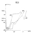
- Figure 9 compares the effects obtained with pulses of 3 ns at 50 GW / cm2 (curve 40) from 30 ns to 9 GW / cm2 (curve 42) and with pulses truncated forward at 25 GW / cm2 (curve 44).
- the effects of the truncated pulse approximate the effects obtained with the 3 ns pulse while in depth they approximate those obtained with the 30 ns pulse.
Landscapes
- Engineering & Computer Science (AREA)
- Chemical & Material Sciences (AREA)
- Mechanical Engineering (AREA)
- Physics & Mathematics (AREA)
- Organic Chemistry (AREA)
- Crystallography & Structural Chemistry (AREA)
- Materials Engineering (AREA)
- Metallurgy (AREA)
- Optics & Photonics (AREA)
- Plasma & Fusion (AREA)
- Thermal Sciences (AREA)
- Laser Beam Processing (AREA)
- Other Surface Treatments For Metallic Materials (AREA)
Claims (12)
- Verfahren zur Behandlung eines Materials mit Laserschocks insbesondere zur Verbesserung der Ermüdungsbeständigkeit dieses Materials, Verfahren, in dem eine Probe aus dem genannten Material mit einer ersten Schicht eines ersten, bei der Wellenlänge der verwendeten Laserstrahlung absorbierenden Materials beschichtet wird und diese erste Schicht mit einer zweiten Schicht eines zweiten Materials beschichtet wird und in dem diese Gesamtheit mit einem Laserstrahlimpuls bestrahlt wird, Verfahren, dadurch gekennzeichnet, daß die Gesamtheit mit mindestens einem Laserimpuls bestrahlt wird, dessen Lichtstrom zunächst unter einem Schwellenwert liegt, unter dem das zweite Material für die verwendete Strahlung lichtdurchlässig ist und über dem es undurchlässig wird, und diesen danach überschreitet.
- Verfahren nach Patentanspruch 1, dadurch gekennzeichnet, daß die Gesamtheit mit mehreren Laserstrahlimpulsen bestrahlt wird.
- Verfahren nach Patentanspruch 2, dadurch gekennzeichnet, daß die Laserimpulse unterschiedlich lange andauern, die einen, kurzen in der Größenordnung einer Nanosekunde, die anderen, längeren in der Größenordnung von zehn Nanosekunden.
- Verfahren nach Patentanspruch 1, dadurch gekennzeichnet, daß der Laserstrahlimpuls eine steil ansteigende Flanke in der Größenordnung einer Nanosekunde und eine Dauer in der Größenordnung von zehn Nanosekunden aufweist.
- Verfahren nach Patentanspruch 1, dadurch gekennzeichnet, daß das Material vor der genannten Schockbehandlung einer Wärmebehandlung unterzogen wird, die darin besteht, daß die unbeschichtete Oberfläche der Probe mit Laserstrahlung behandelt wird.
- Verfahren nach Patentanspruch 5, dadurch gekennzeichnet, daß die zur Wärmebehandlung dienende Laserstrahlung aus mindestens einem Impuls besteht.
- Verfahren nach Patentanspruch 6, dadurch gekennzeichnet, daß der zur Wärmebehandlung dienende Laserimpuls eine Dauer zwischen 0,2 und 100 Nanosekunden aufweist.
- Verfahren nach Patentanspruch 5, dadurch gekennzeichnet, daß die zur Wärmebehandlung dienende Laserstrahlung kontinuierlich ist.
- Verfahren nach Patentanspruch 5, dadurch gekennzeichnet, daß die Wärmebehandlung der unbeschichteten Oberfläche der Probe in Anwesenheit eines mit der Oberfläche in Kontakt stehenden Fluids erfolgt.
- Verfahren nach Patentanspruch 9, dadurch gekennzeichnet, daß das mit der Oberfläche in Kontakt stehende Fluid ein Gas ist.
- Verfahren nach Patentanspruch 9, dadurch gekennzeichnet, daß das mit der Oberfläche in Kontakt stehende Fluid eine Flüssigkeit ist.
- Verfahren nach Patentanspruch 11, dadurch gekennzeichnet, daß die mit der Oberfläche in Kontakt stehende Flüssigkeit flüssiger Stickstoff ist.
Applications Claiming Priority (2)
| Application Number | Priority Date | Filing Date | Title |
|---|---|---|---|
| FR8716717A FR2624138B1 (fr) | 1987-12-02 | 1987-12-02 | Procede de traitement de materiaux par chocs laser |
| FR8716717 | 1987-12-02 |
Publications (2)
| Publication Number | Publication Date |
|---|---|
| EP0319397A1 EP0319397A1 (de) | 1989-06-07 |
| EP0319397B1 true EP0319397B1 (de) | 1992-09-30 |
Family
ID=9357388
Family Applications (1)
| Application Number | Title | Priority Date | Filing Date |
|---|---|---|---|
| EP19880403000 Expired - Lifetime EP0319397B1 (de) | 1987-12-02 | 1988-11-29 | Laser-Schock-Behandlungsverfahren von Materialien |
Country Status (3)
| Country | Link |
|---|---|
| EP (1) | EP0319397B1 (de) |
| DE (1) | DE3875087T2 (de) |
| FR (1) | FR2624138B1 (de) |
Families Citing this family (10)
| Publication number | Priority date | Publication date | Assignee | Title |
|---|---|---|---|---|
| FR2651508B1 (fr) * | 1989-09-05 | 1994-05-13 | Centre Nal Recherc Scientifique | Dispositif de traitement de pieces par chocs laser. |
| CA2072070A1 (en) * | 1990-01-11 | 1991-07-12 | Harold M. Epstein | Material properties |
| FR2709762B1 (fr) * | 1993-09-07 | 1995-12-08 | Aerospatiale | Procédé d'application de chocs laser sur un matériau solide cristallin. |
| EP0666326B1 (de) * | 1993-12-07 | 2001-03-28 | Toyota Jidosha Kabushiki Kaisha | Laser-Schock-Behandlungsverfahren unter Verwendung eines Licht-absorbierenden Materials mit kontrollierter Dicke |
| FR2714320A1 (fr) * | 1993-12-27 | 1995-06-30 | Gec Alsthom Electromec | Procédé de traitement de surface de pièces métalliques pour augmenter leur résistance à la fatigue en milieu corrosif. |
| US6215097B1 (en) * | 1994-12-22 | 2001-04-10 | General Electric Company | On the fly laser shock peening |
| US5741559A (en) * | 1995-10-23 | 1998-04-21 | Lsp Technologies, Inc. | Laser peening process and apparatus |
| DE19643039A1 (de) * | 1996-10-18 | 1998-04-23 | Strunk Horst P Prof Dr | Verfahren zur Veränderung der Kristallstruktur dünner Zonen sowie zur Kristallisation amorpher Schichten durch Druckwellen |
| FR3107710B1 (fr) * | 2020-02-28 | 2022-06-03 | Safran | Procédé de fabrication d’une pièce en acier nitruré |
| CN117987751A (zh) * | 2023-12-27 | 2024-05-07 | 大唐锅炉压力容器检验中心有限公司 | 一种高熵合金的处理方法 |
Family Cites Families (3)
| Publication number | Priority date | Publication date | Assignee | Title |
|---|---|---|---|---|
| US3850698A (en) * | 1972-06-23 | 1974-11-26 | Ind Materials Ltd | Altering material properties |
| EP0085278A1 (de) * | 1982-01-28 | 1983-08-10 | Battelle Development Corporation | Verfahren zum Verändern von Materialeigenschaften durch einen geteilten Laserstrahl |
| US4401477A (en) * | 1982-05-17 | 1983-08-30 | Battelle Development Corporation | Laser shock processing |
-
1987
- 1987-12-02 FR FR8716717A patent/FR2624138B1/fr not_active Expired - Fee Related
-
1988
- 1988-11-29 EP EP19880403000 patent/EP0319397B1/de not_active Expired - Lifetime
- 1988-11-29 DE DE19883875087 patent/DE3875087T2/de not_active Expired - Fee Related
Also Published As
| Publication number | Publication date |
|---|---|
| FR2624138B1 (fr) | 1993-08-13 |
| FR2624138A1 (fr) | 1989-06-09 |
| DE3875087D1 (de) | 1992-11-05 |
| EP0319397A1 (de) | 1989-06-07 |
| DE3875087T2 (de) | 1993-04-22 |
Similar Documents
| Publication | Publication Date | Title |
|---|---|---|
| EP0319397B1 (de) | Laser-Schock-Behandlungsverfahren von Materialien | |
| EP0380387A1 (de) | Oberflächenreinigung mit einem Laser | |
| US20040033702A1 (en) | Deposition of thin films by laser ablation | |
| EP0239432B1 (de) | Verfahren und Vorrichtung zur thermoionischen Behandlung eines Materials in Hinsicht auf die Veränderung seiner physicochemischen Werte | |
| CN1617783A (zh) | 提高激光机加工除材速率的方法与设备 | |
| EP0642846B1 (de) | Verfahren und Vorrichtung zur Überwachung von Oberflächen-Laserreinigung | |
| WO2019002847A1 (en) | METHOD FOR REMOVING COATING WITH PULSED LASER, COMPUTER-READABLE MEDIUM AND LASER | |
| FR2777810A1 (fr) | Procede et dispositif de traitement de la surface interne d'une bouteille de gaz | |
| EP0416988B1 (de) | Vorrichtung zur Laser-Schock-Behandlung von Werkstücken | |
| CH637168A5 (fr) | Procede et dispositif de depot par evaporation sous vide utilisant un faisceau d'electrons module et un ecran. | |
| EP0580534B1 (de) | Verfahren und Vorrichtung zum Vorbehandeln und Beschichten einer Oberfläche | |
| Chen et al. | Analysis of laser damage threshold and morphological changes at the surface of a HgCdTe crystal | |
| EP3551326B1 (de) | Verfahren zur verbesserung der benetzung einer oberfläche eines festen substrats durch ein flüssigmetall | |
| EP3820644B1 (de) | Verfahren zur nanostrukturierung der oberfläche eines materials mittels laser | |
| Stašić et al. | Surface texturing of the carbon steel AISI 1045 using femtosecond laser in single pulse and scanning regime | |
| Sterling et al. | Absorption‐Enhanced Liquid Ablatants for Propulsion with TEA CO2 Laser | |
| EP0012425A1 (de) | Verfahren zur Behandlung einer Wand aus austenitischem rostfreiem Stahl und Schlagvorrichtung zur Durchführung des Verfahrens | |
| Pabst et al. | Selective rear side ablation of thin nickel–chromium-alloy films using ultrashort laser pulses | |
| FR2709762A1 (fr) | Procédé d'application de chocs laser sur un matériau solide cristallin. | |
| Haba et al. | Novel drilling technique in polyimide using visible laser | |
| Ristoscu et al. | Optical emission spectroscopy and time-of-flight investigations of plasmas generated from AlN targets in cases of pulsed laser deposition with sub-ps and ns ultraviolet laser pulses | |
| Kinsman et al. | CO2 laser drilling of copper following excimer laser pretreatment | |
| EP4263110B1 (de) | System und verfahren zur behandlung von material durch laserschock unter einschluss in einer flüssigkeit | |
| FR3031116A1 (fr) | Procede ameliore de decontamination de la surface d'une piece en acier inoxydable | |
| EP0670195A1 (de) | Verfahren zum Entfernen von Beschichtungen auf Fluorcarbon-Kunstharz-Basis |
Legal Events
| Date | Code | Title | Description |
|---|---|---|---|
| PUAI | Public reference made under article 153(3) epc to a published international application that has entered the european phase |
Free format text: ORIGINAL CODE: 0009012 |
|
| AK | Designated contracting states |
Kind code of ref document: A1 Designated state(s): DE FR GB IT |
|
| 17P | Request for examination filed |
Effective date: 19891113 |
|
| 17Q | First examination report despatched |
Effective date: 19910326 |
|
| GRAA | (expected) grant |
Free format text: ORIGINAL CODE: 0009210 |
|
| AK | Designated contracting states |
Kind code of ref document: B1 Designated state(s): DE FR GB IT |
|
| REF | Corresponds to: |
Ref document number: 3875087 Country of ref document: DE Date of ref document: 19921105 |
|
| ITF | It: translation for a ep patent filed | ||
| GBT | Gb: translation of ep patent filed (gb section 77(6)(a)/1977) | ||
| PLBE | No opposition filed within time limit |
Free format text: ORIGINAL CODE: 0009261 |
|
| STAA | Information on the status of an ep patent application or granted ep patent |
Free format text: STATUS: NO OPPOSITION FILED WITHIN TIME LIMIT |
|
| 26N | No opposition filed | ||
| PGFP | Annual fee paid to national office [announced via postgrant information from national office to epo] |
Ref country code: GB Payment date: 20011029 Year of fee payment: 14 |
|
| PGFP | Annual fee paid to national office [announced via postgrant information from national office to epo] |
Ref country code: DE Payment date: 20011114 Year of fee payment: 14 |
|
| PGFP | Annual fee paid to national office [announced via postgrant information from national office to epo] |
Ref country code: FR Payment date: 20011127 Year of fee payment: 14 |
|
| REG | Reference to a national code |
Ref country code: GB Ref legal event code: IF02 |
|
| PG25 | Lapsed in a contracting state [announced via postgrant information from national office to epo] |
Ref country code: GB Free format text: LAPSE BECAUSE OF NON-PAYMENT OF DUE FEES Effective date: 20021129 |
|
| PG25 | Lapsed in a contracting state [announced via postgrant information from national office to epo] |
Ref country code: DE Free format text: LAPSE BECAUSE OF NON-PAYMENT OF DUE FEES Effective date: 20030603 |
|
| GBPC | Gb: european patent ceased through non-payment of renewal fee | ||
| PG25 | Lapsed in a contracting state [announced via postgrant information from national office to epo] |
Ref country code: FR Free format text: LAPSE BECAUSE OF NON-PAYMENT OF DUE FEES Effective date: 20030731 |
|
| REG | Reference to a national code |
Ref country code: FR Ref legal event code: ST |
|
| PG25 | Lapsed in a contracting state [announced via postgrant information from national office to epo] |
Ref country code: IT Free format text: LAPSE BECAUSE OF NON-PAYMENT OF DUE FEES;WARNING: LAPSES OF ITALIAN PATENTS WITH EFFECTIVE DATE BEFORE 2007 MAY HAVE OCCURRED AT ANY TIME BEFORE 2007. THE CORRECT EFFECTIVE DATE MAY BE DIFFERENT FROM THE ONE RECORDED. Effective date: 20051129 |