EP0319217B1 - Method and apparatus for processing picture data - Google Patents
Method and apparatus for processing picture data Download PDFInfo
- Publication number
- EP0319217B1 EP0319217B1 EP88311226A EP88311226A EP0319217B1 EP 0319217 B1 EP0319217 B1 EP 0319217B1 EP 88311226 A EP88311226 A EP 88311226A EP 88311226 A EP88311226 A EP 88311226A EP 0319217 B1 EP0319217 B1 EP 0319217B1
- Authority
- EP
- European Patent Office
- Prior art keywords
- data
- picture data
- unit
- detection
- picture
- Prior art date
- Legal status (The legal status is an assumption and is not a legal conclusion. Google has not performed a legal analysis and makes no representation as to the accuracy of the status listed.)
- Expired - Lifetime
Links
Images



Classifications
-
- H—ELECTRICITY
- H04—ELECTRIC COMMUNICATION TECHNIQUE
- H04N—PICTORIAL COMMUNICATION, e.g. TELEVISION
- H04N5/00—Details of television systems
- H04N5/76—Television signal recording
- H04N5/91—Television signal processing therefor
- H04N5/92—Transformation of the television signal for recording, e.g. modulation, frequency changing; Inverse transformation for playback
- H04N5/926—Transformation of the television signal for recording, e.g. modulation, frequency changing; Inverse transformation for playback by pulse code modulation
- H04N5/9265—Transformation of the television signal for recording, e.g. modulation, frequency changing; Inverse transformation for playback by pulse code modulation with processing of the sound signal
- H04N5/9267—Transformation of the television signal for recording, e.g. modulation, frequency changing; Inverse transformation for playback by pulse code modulation with processing of the sound signal using time division multiplex of the PCM audio and PCM video signals
-
- H—ELECTRICITY
- H04—ELECTRIC COMMUNICATION TECHNIQUE
- H04N—PICTORIAL COMMUNICATION, e.g. TELEVISION
- H04N5/00—Details of television systems
- H04N5/76—Television signal recording
- H04N5/91—Television signal processing therefor
- H04N5/92—Transformation of the television signal for recording, e.g. modulation, frequency changing; Inverse transformation for playback
- H04N5/926—Transformation of the television signal for recording, e.g. modulation, frequency changing; Inverse transformation for playback by pulse code modulation
Definitions
- the present invention relates to a method and apparatus for processing picture data, in which processed are picture data strings of continuously occurring picture data.
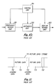
- FIG. 10 is a block diagram showing a prior art picture data processing apparatus
- FIG. 11 is an illustrative diagram showing picture data string inputted to the apparatus shown in FIG. 10.
- the apparatus in FIG. 10 comprises a temporary memory unit 101, an arithmetic unit 102, a display memory unit 103 for use in conjunction with a display, and a control unit 104.
- each data of the picture data strings 111 is made up of a leading data 112 and a picture data 113.
- the apparatus thus arranged operates as follows.
- the picture data strings illustrated in FIG. 11 are entered into the temporary memory unit 101.
- the picture data strings stored, for example, in a disk-like storage medium cannot be displayed on an image plane if such picture data are directly sent to the display memory unit 103. It is therefore necessary to convert the picture data to a data having a structure adapted for displaying.
- the data conversion is effected in the arithmetic unit 102, whereupon the resultant data is inputted to the display memory unit 103 and then outputted to the image plane.
- the arithmetic operation is effected on image plane basis.
- the leading data 112 is used to recognize the picture data 113 for one image plane.
- Such processings are carried out under control of the control unit 104.
- the processings cannot be implemented in the case when one image plane data conversion time is longer than a period of time during which one image plane data is inputted to the temporary memory unit 101.
- the processings cannot be implemented in the case when one unitary picture data conversion time is larger than a period of time during which the unitary picture data is inputted to the temporary memory unit. That is, a problem exists in that the operation cannot be performed in the case where the control unit is incapable of controlling the input of the picture data strings. This may occur when the picture data strings recorded in a compact disk which is generally used for recording and playing back audio information is intended to be sequentially played back.
- the present invention provides an apparatus for processing continuously inputted picture data strings each being composed of successively occurring units of picture data, each unit of picture data having a commencement data indicative of commencement of the unit of picture data, said apparatus comprising: first detecting means for detecting said commencement data of each unit of picture data from said input picture data strings and providing a first detection data indicative of the detection of said commencement data; gate means for controlling transferring of the unit of picture data whose commencement data has been detected by said first detecting means; first memory means for temporarily storing the unit of picture data transferred by said gate means; conversion means for converting the unit of picture data stored in said first memory means to a data of a form adapted for displaying and outputting the resultant data; second memory means for storing said data outputted from said conversion means; and display means for displaying said data stored in said second memory means, characterised by further comprising: second detecting means for detecting termination of a conversion of the unit of picture data by said conversion means and providing a second detection data indicative of the detection of the
- a method of processing continuously inputted picture data strings each being composed of successively occurring units of picture data, each unit of picture data having a commencement data indicative of commencement of the unit of picture data comprising the steps of: monitoring each said input picture data strings for detecting said commencement data of each unit of picture data from said input picture data strings and providing, upon detection of said commencement data, a first detection data indicative of the detection of said commencement data; temporarily storing the unit of picture data whose commencement data has been detected in a memory; converting the temporarily stored unit of picture data to a data of a form adapted for displaying; and displaying the data obtained by said converting step, characterized by further comprising the steps of: monitoring said converting step for detecting termination of a conversion of the unit picture data by said converting step and providing, upon detection of the termination of the conversion a second detection data indicative of the detection of the termination of the conversion; and controlling said storing step in response to said first detection data and said second detection data to operate such that
- the picture data strings inputted independently of the processing ability of the control means can be processed and outputted depending upon the processing ability of the apparatus.
- the apparatus is advantageous in that it is capable of processing picture data entering at different speeds.
- the picture data processing apparatus according to the present invention is particularly advantageous when the picture data strings recorded in a compact disk is played back and processed.
- FIGS. 1 through 5 A picture data processing apparatus according to one embodiment of the present invention will now be described with reference to FIGS. 1 through 5.
- FIG. 1 is a block diagram showing an arrangement of the picture data processing apparatus according to the invention, in which one image plane data is desinged as a unitary picture data.
- the arrangement in FIG. 1 includes an image plane commencement data detecting unit 1, a gate unit 2, a temporary memory unit 3, an arithmetic unit 4, an arithmetic operation termination data detecting unit 5, a display memory unit 6 for use in conjunction with a display, and a control unit 7.
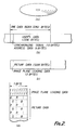
- FIG. 2 is an illustrative diagram showing picture data strings inputted to the apparatus shown in FIG. 1, in which FIG. 2(a) shows a schematic diagram showing a CD-ROM disk in which stored picture data strings are recorded, FIGS.
- FIG. 2(b) and 2(c) are illustrative diagrams showing the picture data strings
- FIG. 2(d) is a diagram showing a bit pattern of the picture data string.
- FIG. 3 is a block diagram showing an arrangement of a system which stores, processes, and displays the picture data, in which included are a CD-ROM playback device 31, a picture data processing device 32 and a picture data displaying device 33.
- FIG. 4 is a detailed block diagram showing the picture data processing apparatus shown in FIG. 1. The arrangement in FIG.
- FIG. 4 includes a register 41, a shift register 42, a comparator 43, a shift register 44, a clock generator 45, an AND circuit 46, a temporary storing RAM 47, a display RAM 48, an address computing circuit 49, a counter 50, a CPU 51, a memory 52, and I/O ports 53, 54, 55.
- FIG. 5 is a flow chart for explaining the processing of the control device shown in FIG. 1.
- one image plane data is designed as a unitary picture data and the picture data strings are recorded in the CD-ROM (Compact Disc-Read Only Memory) disk shown in FIG. 2(a).
- CD-ROM Compact Disc-Read Only Memory
- digital data are recorded in place of pieces of music as normally recorded therein.
- the digital data has a structure such that 2352-byte data are combined as one data block, and the one data block is composed of 12-byte synchronizing signal, 4-byte address data, and 2336-byte user's data region.
- the picture data strings are recorded in the user's data region, and a structure of such picture data strings is as shown in FIG. 2(c).
- the unitary picture data is made up of image plane leading data and one image plane picture data.
- FIG. 2(d) illustrates a bit pattern of the unitary picture data, in which the image plane leading data is made up of 2-byte data of all "1".
- One pixel of the picture data is represented by 2-byte, in which 5-bit data is allocated to each of red (R), green (G) and blue (B) with one bit of "0" at the leading portion. Accordingly, the data for one image plane including 512 X 400 pixels contains 500 kilobyte data.
- FIG. 3 is a system for displaying a picture recorded in the CD-ROM disk.
- the CD-ROM disk playback device 31 plays back the picture data strings from the CD-ROM disk, the resultant data is processed in the picture data processing device 32, and the data being processed is outputted to the picture data displaying device 33, such as a CRT display.
- the input picture data is stored in the shift register 42 to compare it with the leading data in the register 41, whereby input of the subsequent image plane picture data is detected.
- termination of conversion of the one image plane picture data is monitored by the arithmetic operation termination data detecting unit 5. This can be easily achieved, since the amount of the data for one image plane is known in advance. As shown in the block (f) in FIG. 4, this is implemented in such a manner that while resetting the counter 50 in response to the image plane commencement signal fed from the comparator 43, the amount of data for one image plane is counted up.
- the control unit 7 executes processings in accordance with the flow chart shown in FIG. 5. Specifically, the occurence of the first detection data is being monitored, and when the second detection data has been detected at the time when the first detection data has been detected, the one image plane data as identified by the first detection data is sent to the temporary memory unit 3 while controlling the gate unit 2. When the second detection data has not yet been detected, that data is not sent to the temporary memory unit 3 while controlling the gate unit 2 and is made invalid.
- the control unit 7 corresponds in FIG.
- the gate unit 2 is implemented by the block (b) in FIG. 4 in which shift clocks to the shift register 44 are applied from the clock generator 45 through the AND circuit 46 which is controlled by the CPU 51. As such, transfer of the picture data to the subsequent stage is controllable by the CPU 51.
- the temporary memory unit 3 is implemented by the temporary storing RAM 47 in FIG. 4, and the display memory unit 6 by the display RAM 48 in FIG. 4.
- the arithmetic unit 4 is implemented by the address computing circuit 49 in FIG. 4 in which one pixel data of 2-bytes is read out of the temporary storing RAM 47, rearranged to 5-bit data corresponding to each of red, green and blue, and those are stored in prescribed address locations of the display RAM 48.
- the commencement of the picture data and conversion operation are monitored on one image plane basis, and the image data inputted during the arithmetic operation is made invalid. Therefore, the operation of the apparatus is ensured even if the data are inputted in excess of processing ability of the apparatus.
- blocks (a), (b), (d) and (f) in FIG. 4 corresponding respectively to the image plane commencement data detecting unit, the gate unit, the arithmetic unit and the arithmetic operation termination data detecting unit are hardware arrangements, these units can also be implemented with software.
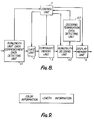
- FIG. 6 is a block diagram showing a picture data processing apparatus according to the invention in which one line data is designed as the unitary picture data. Operation of the apparatus is similar to the above except that commencement of the one line data is detected by a one line commencement data detecting unit 61. In this case, when the picture data is made invalid, it is possible to substitute the invalid data with the preceding one line data.
- FIG. 7 is a block diagram showing the picture data processing apparatus according to the invention, in which the picture data are of runlength coding and one line data is designed as the unitary picture data.
- the arithmetic unit is replaced by a runlength decoding unit 62, and the arithmetic operation termination data detecting unit by a decoding termination data detecting unit 63.
- the operation of the apparatus is similar to that shown in FIG. 6.
- FIG. 8 is a block diagram showing a picture data processing apparatus according to the invention in which the runlength unit data is designed as the unitary picture data.
- the runlength unit data has a variable length in which detection of commencement of the unitary data is carried out by a runlength unit data commencement data detecting unit 64.
- the processings of the data can also be similary executed.
Landscapes
- Engineering & Computer Science (AREA)
- Multimedia (AREA)
- Signal Processing (AREA)
- Image Processing (AREA)
Description
- The present invention relates to a method and apparatus for processing picture data, in which processed are picture data strings of continuously occurring picture data.
- Recently, due to availability of low-priced, high-capacity semiconductor memories and appearance of large capacity storage mediums, such as optical disk, it has become possible to easily deal with a large amount of digital data, especially picture data.
- A prior art picture data processing apparatus will be described with reference to the drawings. FIG. 10 is a block diagram showing a prior art picture data processing apparatus, and FIG. 11 is an illustrative diagram showing picture data string inputted to the apparatus shown in FIG. 10. The apparatus in FIG. 10 comprises a
temporary memory unit 101, anarithmetic unit 102, adisplay memory unit 103 for use in conjunction with a display, and acontrol unit 104. In FIG. 11, each data of thepicture data strings 111 is made up of a leadingdata 112 and apicture data 113. - The apparatus thus arranged operates as follows. The picture data strings illustrated in FIG. 11 are entered into the
temporary memory unit 101. It should be noted that due to difference in data structure, the picture data strings stored, for example, in a disk-like storage medium cannot be displayed on an image plane if such picture data are directly sent to thedisplay memory unit 103. It is therefore necessary to convert the picture data to a data having a structure adapted for displaying. In the apparatus in FIG. 10, the data conversion is effected in thearithmetic unit 102, whereupon the resultant data is inputted to thedisplay memory unit 103 and then outputted to the image plane. The arithmetic operation is effected on image plane basis. To this effect, the leadingdata 112 is used to recognize thepicture data 113 for one image plane. Such processings are carried out under control of thecontrol unit 104. - In the prior art picture data processing apparatus, the processings cannot be implemented in the case when one image plane data conversion time is longer than a period of time during which one image plane data is inputted to the
temporary memory unit 101. As a rule, the processings cannot be implemented in the case when one unitary picture data conversion time is larger than a period of time during which the unitary picture data is inputted to the temporary memory unit. That is, a problem exists in that the operation cannot be performed in the case where the control unit is incapable of controlling the input of the picture data strings. This may occur when the picture data strings recorded in a compact disk which is generally used for recording and playing back audio information is intended to be sequentially played back. - In view of the foregoing, it is an object of the present invention to provide a method and apparatus for processing picture data, in which picture data can be processed depending upon the processing ability of the apparatus even in the case where the picture data are inputted independently of the processing ability of the apparatus.
- In order to attain the above object, the present invention provides an apparatus for processing continuously inputted picture data strings each being composed of successively occurring units of picture data, each unit of picture data having a commencement data indicative of commencement of the unit of picture data, said apparatus comprising:
first detecting means for detecting said commencement data of each unit of picture data from said input picture data strings and providing a first detection data indicative of the detection of said commencement data;
gate means for controlling transferring of the unit of picture data whose commencement data has been detected by said first detecting means;
first memory means for temporarily storing the unit of picture data transferred by said gate means;
conversion means for converting the unit of picture data stored in said first memory means to a data of a form adapted for displaying and outputting the resultant data;
second memory means for storing said data outputted from said conversion means; and
display means for displaying said data stored in said second memory means,
characterised by further comprising:
second detecting means for detecting termination of a conversion of the unit of picture data by said conversion means and providing a second detection data indicative of the detection of the termination of the conversion; and
control means responsive to said first detection data and said second detection data for controlling said gate means to operate such that the unit of picture data whose commencement data has been detected by said first detecting means is transferred through said gate means when said first detection data has occurred subsequent to an occurrence of said second detection data and is not transferred through said gate means when no said second detection data has occurred prior to an occurrence of said first detection data. - According to another aspect of the present invention, there is provided a method of processing continuously inputted picture data strings each being composed of successively occurring units of picture data, each unit of picture data having a commencement data indicative of commencement of the unit of picture data, said method comprising the steps of:
monitoring each said input picture data strings for detecting said commencement data of each unit of picture data from said input picture data strings and providing, upon detection of said commencement data, a first detection data indicative of the detection of said commencement data;
temporarily storing the unit of picture data whose commencement data has been detected in a memory;
converting the temporarily stored unit of picture data to a data of a form adapted for displaying; and
displaying the data obtained by said converting step,
characterized by further comprising the steps of:
monitoring said converting step for detecting termination of a conversion of the unit picture data by said converting step and providing, upon detection of the termination of the conversion a second detection data indicative of the detection of the termination of the conversion; and
controlling said storing step in response to said first detection data and said second detection data to operate such that the unit of picture data whose commencement data has been detected is stored in said memory when said first detection data has occurred subsequent to an occurrence of said second detection data and is not stored in said memory when no said second detection data has occurred prior to an occurrence of said first detection data. - In accordance with the method and apparatus as described, the picture data strings inputted independently of the processing ability of the control means can be processed and outputted depending upon the processing ability of the apparatus. Further, the apparatus is advantageous in that it is capable of processing picture data entering at different speeds. The picture data processing apparatus according to the present invention is particularly advantageous when the picture data strings recorded in a compact disk is played back and processed.
- FIG. 1 is a block diagram showing an arrangement of a picture data processing apparatus according to the present invention, in which one image plane data is designed to be a unitary picture data;
- FIG. 2 is a diagram showing a status of storage of the picture data;
- FIG. 3 is a block diagram showing an arrangement of a system which stores, processes, and displays the picture data;
- FIG. 4 is a block diagram showing a detailed arrangement of the apparatus shown in FIG. 1;
- FIG. 5 is a flow chart for explaining the processings of a control unit shown in FIG. 1;
- FIG. 6 is a block diagram showing a picture data processing apparatus according to the present invention, in which one line data is designed to be a unitary picture data;
- FIG. 7 is a block diagram showing an arrangement of a picture data processing apparatus according to the present invention, in which one line of runlength coded picture data is designed to be a unitary picture data;
- FIG. 8 is a block diagram showing an arrangement of a picture data processing apparatus according to the present invention, in which a runlength unit of runlength coded picture data is designed to be a unitary picture data;
- FIG. 9 is an illustrative diagram showing a structure of a runlength coded picture data;
- FIG. 10 is a block diagram showing an arrangement of a conventional picture data processing apparatus for processing picture data; and
- FIG. 11 is an illustrative diagram showing picture data strings inputted to the apparatus shown in FIG. 10.
- A picture data processing apparatus according to one embodiment of the present invention will now be described with reference to FIGS. 1 through 5.
- FIG. 1 is a block diagram showing an arrangement of the picture data processing apparatus according to the invention, in which one image plane data is desinged as a unitary picture data. The arrangement in FIG. 1 includes an image plane commencement
data detecting unit 1, agate unit 2, atemporary memory unit 3, anarithmetic unit 4, an arithmetic operation terminationdata detecting unit 5, adisplay memory unit 6 for use in conjunction with a display, and acontrol unit 7. FIG. 2 is an illustrative diagram showing picture data strings inputted to the apparatus shown in FIG. 1, in which FIG. 2(a) shows a schematic diagram showing a CD-ROM disk in which stored picture data strings are recorded, FIGS. 2(b) and 2(c) are illustrative diagrams showing the picture data strings, and FIG. 2(d) is a diagram showing a bit pattern of the picture data string. FIG. 3 is a block diagram showing an arrangement of a system which stores, processes, and displays the picture data, in which included are a CD-ROM playback device 31, a picturedata processing device 32 and a picturedata displaying device 33. FIG. 4 is a detailed block diagram showing the picture data processing apparatus shown in FIG. 1. The arrangement in FIG. 4 includes aregister 41, ashift register 42, acomparator 43, a shift register 44, aclock generator 45, anAND circuit 46, atemporary storing RAM 47, adisplay RAM 48, anaddress computing circuit 49, acounter 50, aCPU 51, a memory 52, and I/O ports - Operation will next be described. According to this embodiment, one image plane data is designed as a unitary picture data and the picture data strings are recorded in the CD-ROM (Compact Disc-Read Only Memory) disk shown in FIG. 2(a). In the CD-ROM disk, digital data are recorded in place of pieces of music as normally recorded therein. As shown in FIG. 2(b), the digital data has a structure such that 2352-byte data are combined as one data block, and the one data block is composed of 12-byte synchronizing signal, 4-byte address data, and 2336-byte user's data region. In this embodiment, the picture data strings are recorded in the user's data region, and a structure of such picture data strings is as shown in FIG. 2(c). The unitary picture data is made up of image plane leading data and one image plane picture data. FIG. 2(d) illustrates a bit pattern of the unitary picture data, in which the image plane leading data is made up of 2-byte data of all "1". One pixel of the picture data is represented by 2-byte, in which 5-bit data is allocated to each of red (R), green (G) and blue (B) with one bit of "0" at the leading portion. Accordingly, the data for one image plane including 512 X 400 pixels contains 500 kilobyte data.
- FIG. 3 is a system for displaying a picture recorded in the CD-ROM disk. The CD-ROM
disk playback device 31 plays back the picture data strings from the CD-ROM disk, the resultant data is processed in the picturedata processing device 32, and the data being processed is outputted to the picturedata displaying device 33, such as a CRT display. - Operations performed in the picture
data processing device 32 will be described. When the picture data strings as shown in FIG. 2 is inputted to the picture data processing device shown in FIG. 1, it is temporarily stored in thetemporary memory unit 3 and is converted to a proper form in thearithmetic unit 4, and is then sent to thememory unit 6 in the similar fashion as in the prior art apparatus. It is now assumed that the unitary picture data stored in thetemporary memory unit 3 has been subjected to conversion in thearithmetic unit 4 and the resultant data is transferred to thememory unit 6. At this time, when the subsequent one image plane picture data is inputted to the picture data processing apparatus, the input of such data is detected by the image plane commencementdata detecting unit 1. This can be implemented by detecting the bit pattern of the leading data shown in FIG. 2(d). To be more specific, as shown in block (a) of FIG. 4, while storing the bit pattern of the leading data in theregister 41, the input picture data is stored in theshift register 42 to compare it with the leading data in theregister 41, whereby input of the subsequent image plane picture data is detected. On the other hand, termination of conversion of the one image plane picture data is monitored by the arithmetic operation terminationdata detecting unit 5. This can be easily achieved, since the amount of the data for one image plane is known in advance. As shown in the block (f) in FIG. 4, this is implemented in such a manner that while resetting thecounter 50 in response to the image plane commencement signal fed from thecomparator 43, the amount of data for one image plane is counted up. - Based on a first detection data supplied from the image plane commencement
data detecting unit 1 and a second detection data supplied from the arithmetic operation terminationdata detecting unit 5, thecontrol unit 7 executes processings in accordance with the flow chart shown in FIG. 5. Specifically, the occurence of the first detection data is being monitored, and when the second detection data has been detected at the time when the first detection data has been detected, the one image plane data as identified by the first detection data is sent to thetemporary memory unit 3 while controlling thegate unit 2. When the second detection data has not yet been detected, that data is not sent to thetemporary memory unit 3 while controlling thegate unit 2 and is made invalid. Thecontrol unit 7 corresponds in FIG. 4 to the block (g) where theCPU 51 implements a program stored in the memory 52 in which the above-described processing contents are incorporated. Reading of the detection data into theCPU 51 and output of a control signal from theCPU 51 to the gate unit are carried out through the I/O ports gate unit 2 is implemented by the block (b) in FIG. 4 in which shift clocks to the shift register 44 are applied from theclock generator 45 through the ANDcircuit 46 which is controlled by theCPU 51. As such, transfer of the picture data to the subsequent stage is controllable by theCPU 51. Thetemporary memory unit 3 is implemented by thetemporary storing RAM 47 in FIG. 4, and thedisplay memory unit 6 by thedisplay RAM 48 in FIG. 4. Thearithmetic unit 4 is implemented by theaddress computing circuit 49 in FIG. 4 in which one pixel data of 2-bytes is read out of thetemporary storing RAM 47, rearranged to 5-bit data corresponding to each of red, green and blue, and those are stored in prescribed address locations of thedisplay RAM 48. - As described, according to this embodiment, the commencement of the picture data and conversion operation are monitored on one image plane basis, and the image data inputted during the arithmetic operation is made invalid. Therefore, the operation of the apparatus is ensured even if the data are inputted in excess of processing ability of the apparatus.
- Although blocks (a), (b), (d) and (f) in FIG. 4 corresponding respectively to the image plane commencement data detecting unit, the gate unit, the arithmetic unit and the arithmetic operation termination data detecting unit are hardware arrangements, these units can also be implemented with software.
- In the above embodiment, one image plane data is designed as a unitary picture data. FIG. 6 is a block diagram showing a picture data processing apparatus according to the invention in which one line data is designed as the unitary picture data. Operation of the apparatus is similar to the above except that commencement of the one line data is detected by a one line commencement
data detecting unit 61. In this case, when the picture data is made invalid, it is possible to substitute the invalid data with the preceding one line data. - Another embodiment will next be described in which the picture data is of runlength coding. In runlength coding, successive picture elements of the same color are subjected to encoding, and as shown in FIG. 9, the color information and the length information are encoded. FIG. 7 is a block diagram showing the picture data processing apparatus according to the invention, in which the picture data are of runlength coding and one line data is designed as the unitary picture data. In this case, the arithmetic unit is replaced by a
runlength decoding unit 62, and the arithmetic operation termination data detecting unit by a decoding terminationdata detecting unit 63. The operation of the apparatus is similar to that shown in FIG. 6. - FIG. 8 is a block diagram showing a picture data processing apparatus according to the invention in which the runlength unit data is designed as the unitary picture data. The runlength unit data has a variable length in which detection of commencement of the unitary data is carried out by a runlength unit data commencement data detecting unit 64. The processings of the data can also be similary executed.
- Although various unitary data are exemplified, it would be apparent to those skilled in the art that the method and apparatus according to the invention are generally applicable to a unitary data defined as desired.
Claims (6)
- An apparatus for processing continuously inputted picture data strings each being composed of successively occurring units of picture data, each unit of picture data having a commencement data indicative of commencement of the unit of picture data, said apparatus comprising:
first detecting means (1,61,64) for detecting said commencement data of each unit of picture data from said input picture data strings and providing a first detection data indicative of the detection of said commencement data;
gate means (2) for controlling transferring of the unit of picture data whose commencement data has been detected by said first detecting means;
first memory means (3) for temporarily storing the unit of picture data transferred by said gate means;
conversion means (4,62) for converting the unit of picture data stored in said first memory means to a data of a form adapted for displaying and outputting the resultant data;
second memory means (6) for storing said data outputted from said conversion means; and
display means (33) for displaying said data stored in said second memory means,
characterised by further comprising:
second detecting means (5,63) for detecting termination of a conversion of the unit of picture data by said conversion means and providing a second detection data indicative of the detection of the termination of the conversion; and
control means (7) responsive to said first detection data and said second detection data for controlling said gate means to operate such that the unit of picture data whose commencement data has been detected by said first detecting means is transferred through said gate means when said first detection data has occurred subsequent to an occurrence of said second detection data and is not transferred through said gate means when no said second detection data has occurred prior to an occurrence of said first detection data. - The apparatus according to claim 1, wherein each said unit of picture data amounts to a single image plane of said display means.
- The apparatus according to claim 1, wherein each said unit of picture data amounts to a single line, and wherein when no second detection data has occurred prior to an occurrence of said first detection data, said control means (7) controls said second memory means (6) such that a one line preceding picture data which has been subjected to conversion operation by said conversion means (4,62) is duplicated in said second memory means to provide the same data as the one line preceding data.
- The apparatus according to claim 3, wherein said picture data is a string of runlength coded data in which color information representing a color and length information representing a length of the color information are coded.
- The apparatus according to claim 1, wherein said picture data is a string of runlength coded data in which color information representing a color and length information representing a length of the color information are coded, and wherein each said unit of picture data amounts to one said runlength coded data.
- A method of processing continuously inputted picture data strings each being composed of successively occurring units of picture data, each unit of picture data having a commencement data indicative of commencement of the unit of picture data, said method comprising the steps of:
monitoring each said input picture data strings for detecting said commencement data of each unit of picture data from said input picture data strings and providing, upon detection of said commencement data, a first detection data indicative of the detection of said commencement data;
temporarily storing the unit of picture data whose commencement data has been detected in a memory;
converting the temporarily stored unit of picture data to a data of a form adapted for displaying; and
displaying the data obtained by said converting step,
characterized by further comprising the steps of:
monitoring said converting step for detecting termination of a conversion of the unit picture data by said converting step and providing, upon detection of the termination of the conversion a second detection data indicative of the detection of the termination of the conversion; and
controlling said storing step in response to said first detection data and said second detection data to operate such that the unit of picture data whose commencement data has been detected is stored in said memory when said first detection data has occurred subsequent to an occurrence of said second detection data and is not stored in said memory when no said second detection data has occurred prior to an occurrence of said first detection data.
Applications Claiming Priority (4)
| Application Number | Priority Date | Filing Date | Title |
|---|---|---|---|
| JP302238/87 | 1987-11-30 | ||
| JP62302238A JPH01142793A (en) | 1987-11-30 | 1987-11-30 | Image data control device |
| JP62312762A JPH01152872A (en) | 1987-12-10 | 1987-12-10 | Picture data controller |
| JP312762/87 | 1987-12-10 |
Publications (3)
| Publication Number | Publication Date |
|---|---|
| EP0319217A2 EP0319217A2 (en) | 1989-06-07 |
| EP0319217A3 EP0319217A3 (en) | 1991-10-09 |
| EP0319217B1 true EP0319217B1 (en) | 1995-01-18 |
Family
ID=26563033
Family Applications (1)
| Application Number | Title | Priority Date | Filing Date |
|---|---|---|---|
| EP88311226A Expired - Lifetime EP0319217B1 (en) | 1987-11-30 | 1988-11-25 | Method and apparatus for processing picture data |
Country Status (3)
| Country | Link |
|---|---|
| US (1) | US5033007A (en) |
| EP (1) | EP0319217B1 (en) |
| DE (1) | DE3852815T2 (en) |
Families Citing this family (5)
| Publication number | Priority date | Publication date | Assignee | Title |
|---|---|---|---|---|
| US5377344A (en) * | 1991-07-31 | 1994-12-27 | Toyo Corporation | Selective memory transaction monitor system |
| US5406324A (en) * | 1992-10-30 | 1995-04-11 | Roth; Alexander | Surveillance system for transmitting images via a radio transmitter |
| US5608538A (en) * | 1994-08-24 | 1997-03-04 | International Business Machines Corporation | Scan line queuing for high performance image correction |
| US5868707A (en) | 1996-08-15 | 1999-02-09 | Advanced Cardiovascular Systems, Inc. | Protective sheath for catheter balloons |
| US7105013B2 (en) * | 2002-09-30 | 2006-09-12 | Advanced Cardiovascular Systems, Inc. | Protective sleeve assembly for a balloon catheter |
Family Cites Families (11)
| Publication number | Priority date | Publication date | Assignee | Title |
|---|---|---|---|---|
| US3974326A (en) * | 1973-06-08 | 1976-08-10 | Hasler Ag | Facsimile communication system |
| JPS5135219A (en) * | 1974-09-20 | 1976-03-25 | Nippon Electric Co | |
| US4206476A (en) * | 1976-02-24 | 1980-06-03 | Sony Corporation | Control circuit for use with a time-compression/time-expansion system in a pulse signal record/playback device |
| US4161753A (en) * | 1977-07-08 | 1979-07-17 | International Business Machines Corporation | Video recording disk with interlacing of data for frames on the same track |
| US4319331A (en) * | 1980-01-28 | 1982-03-09 | Nestor Associates | Curve follower |
| US4361849A (en) * | 1980-11-06 | 1982-11-30 | Rca Corporation | Video disc vari-speed playback system |
| JPS5963014A (en) * | 1982-10-04 | 1984-04-10 | Victor Co Of Japan Ltd | Information recording disk and its reproducing device |
| SE448789B (en) * | 1983-03-29 | 1987-03-16 | Ericsson Telefon Ab L M | DEVICE FOR GENERATING IMAGES IN A COMPUTER PRESENTATION SYSTEM RASTER ON A SCREEN SCREEN |
| JPS60125885A (en) * | 1983-12-13 | 1985-07-05 | 沖電気工業株式会社 | Movement of cursor |
| US4779210A (en) * | 1984-05-02 | 1988-10-18 | Hitachi Engineering, Co. Ltd. | Graphic processing apparatus |
| JPS61237676A (en) * | 1985-04-13 | 1986-10-22 | Brother Ind Ltd | Recorder with image-forming range appropriateness discriminating function |
-
1988
- 1988-11-23 US US07/274,812 patent/US5033007A/en not_active Expired - Fee Related
- 1988-11-25 DE DE3852815T patent/DE3852815T2/en not_active Expired - Fee Related
- 1988-11-25 EP EP88311226A patent/EP0319217B1/en not_active Expired - Lifetime
Also Published As
| Publication number | Publication date |
|---|---|
| DE3852815T2 (en) | 1995-08-10 |
| EP0319217A3 (en) | 1991-10-09 |
| DE3852815D1 (en) | 1995-03-02 |
| EP0319217A2 (en) | 1989-06-07 |
| US5033007A (en) | 1991-07-16 |
Similar Documents
| Publication | Publication Date | Title |
|---|---|---|
| US5559562A (en) | MPEG editor method and apparatus | |
| AU641726B2 (en) | Transmission system for digitised television images | |
| JPH0828053B2 (en) | Data recording method | |
| US6389171B1 (en) | Method and apparatus for a digital video cassette (DVC) decode system | |
| JPS60220682A (en) | Video signal processor | |
| EP0647067B1 (en) | Error correction for digital video data | |
| KR0140096B1 (en) | A digital video image compression and display method, a personal computer system therefor and a digital storage device for storing the compressed digital signal | |
| US6771877B1 (en) | Data processing method, data processing apparatus and program recording medium | |
| US5033007A (en) | Apparatus for processing continuously inputted picture data strings | |
| GB2167917A (en) | Video record for use with computer controlled player/monitor systems | |
| EP0405885A1 (en) | Recording device and reproducing device | |
| US5594550A (en) | Digital signal recording apparatus for recording digital data comprising a plurality of recording blocks | |
| EP0602896A2 (en) | Digital video cassette recorder | |
| KR920003000B1 (en) | Image data processing method and apparatus | |
| JP3312456B2 (en) | Video signal processing device | |
| JP3402581B2 (en) | Data restoration device | |
| JP3115013B2 (en) | Image display device | |
| JPH0283579A (en) | Image data display device and image data display method | |
| JP3341429B2 (en) | Video signal processing device | |
| JPH0283578A (en) | Image data display device and image data display method | |
| US5455683A (en) | Method for preventing error speading while recording compressed image data | |
| JP2664473B2 (en) | Image data storage and playback method | |
| JPH0741261Y2 (en) | Telop device | |
| KR970002478B1 (en) | Data Distribution Circuit in Parallel Image Decoder | |
| JPH0447879A (en) | Digital signal recording and reproducing system |
Legal Events
| Date | Code | Title | Description |
|---|---|---|---|
| PUAI | Public reference made under article 153(3) epc to a published international application that has entered the european phase |
Free format text: ORIGINAL CODE: 0009012 |
|
| AK | Designated contracting states |
Kind code of ref document: A2 Designated state(s): DE FR GB NL |
|
| PUAL | Search report despatched |
Free format text: ORIGINAL CODE: 0009013 |
|
| AK | Designated contracting states |
Kind code of ref document: A3 Designated state(s): DE FR GB NL |
|
| 17P | Request for examination filed |
Effective date: 19920317 |
|
| 17Q | First examination report despatched |
Effective date: 19931019 |
|
| GRAA | (expected) grant |
Free format text: ORIGINAL CODE: 0009210 |
|
| AK | Designated contracting states |
Kind code of ref document: B1 Designated state(s): DE FR GB NL |
|
| REF | Corresponds to: |
Ref document number: 3852815 Country of ref document: DE Date of ref document: 19950302 |
|
| ET | Fr: translation filed | ||
| PGFP | Annual fee paid to national office [announced via postgrant information from national office to epo] |
Ref country code: FR Payment date: 19951109 Year of fee payment: 8 |
|
| PGFP | Annual fee paid to national office [announced via postgrant information from national office to epo] |
Ref country code: GB Payment date: 19951116 Year of fee payment: 8 |
|
| PLBE | No opposition filed within time limit |
Free format text: ORIGINAL CODE: 0009261 |
|
| STAA | Information on the status of an ep patent application or granted ep patent |
Free format text: STATUS: NO OPPOSITION FILED WITHIN TIME LIMIT |
|
| PGFP | Annual fee paid to national office [announced via postgrant information from national office to epo] |
Ref country code: DE Payment date: 19951128 Year of fee payment: 8 |
|
| PGFP | Annual fee paid to national office [announced via postgrant information from national office to epo] |
Ref country code: NL Payment date: 19951129 Year of fee payment: 8 |
|
| 26N | No opposition filed | ||
| PG25 | Lapsed in a contracting state [announced via postgrant information from national office to epo] |
Ref country code: GB Effective date: 19961125 |
|
| PG25 | Lapsed in a contracting state [announced via postgrant information from national office to epo] |
Ref country code: NL Effective date: 19970601 |
|
| GBPC | Gb: european patent ceased through non-payment of renewal fee |
Effective date: 19961125 |
|
| PG25 | Lapsed in a contracting state [announced via postgrant information from national office to epo] |
Ref country code: FR Effective date: 19970731 |
|
| NLV4 | Nl: lapsed or anulled due to non-payment of the annual fee |
Effective date: 19970601 |
|
| PG25 | Lapsed in a contracting state [announced via postgrant information from national office to epo] |
Ref country code: DE Effective date: 19970801 |
|
| REG | Reference to a national code |
Ref country code: FR Ref legal event code: ST |