EP0318772B1 - Optical focus position control device - Google Patents
Optical focus position control device Download PDFInfo
- Publication number
- EP0318772B1 EP0318772B1 EP19880119199 EP88119199A EP0318772B1 EP 0318772 B1 EP0318772 B1 EP 0318772B1 EP 19880119199 EP19880119199 EP 19880119199 EP 88119199 A EP88119199 A EP 88119199A EP 0318772 B1 EP0318772 B1 EP 0318772B1
- Authority
- EP
- European Patent Office
- Prior art keywords
- focussing
- focus position
- optical focus
- tracking
- optical
- Prior art date
- Legal status (The legal status is an assumption and is not a legal conclusion. Google has not performed a legal analysis and makes no representation as to the accuracy of the status listed.)
- Expired
Links
Images


Classifications
-
- G—PHYSICS
- G11—INFORMATION STORAGE
- G11B—INFORMATION STORAGE BASED ON RELATIVE MOVEMENT BETWEEN RECORD CARRIER AND TRANSDUCER
- G11B11/00—Recording on or reproducing from the same record carrier wherein for these two operations the methods are covered by different main groups of groups G11B3/00 - G11B7/00 or by different subgroups of group G11B9/00; Record carriers therefor
- G11B11/10—Recording on or reproducing from the same record carrier wherein for these two operations the methods are covered by different main groups of groups G11B3/00 - G11B7/00 or by different subgroups of group G11B9/00; Record carriers therefor using recording by magnetic means or other means for magnetisation or demagnetisation of a record carrier, e.g. light induced spin magnetisation; Demagnetisation by thermal or stress means in the presence or not of an orienting magnetic field
- G11B11/105—Recording on or reproducing from the same record carrier wherein for these two operations the methods are covered by different main groups of groups G11B3/00 - G11B7/00 or by different subgroups of group G11B9/00; Record carriers therefor using recording by magnetic means or other means for magnetisation or demagnetisation of a record carrier, e.g. light induced spin magnetisation; Demagnetisation by thermal or stress means in the presence or not of an orienting magnetic field using a beam of light or a magnetic field for recording by change of magnetisation and a beam of light for reproducing, i.e. magneto-optical, e.g. light-induced thermomagnetic recording, spin magnetisation recording, Kerr or Faraday effect reproducing
- G11B11/1055—Disposition or mounting of transducers relative to record carriers
- G11B11/10576—Disposition or mounting of transducers relative to record carriers with provision for moving the transducers for maintaining alignment or spacing relative to the carrier
-
- G—PHYSICS
- G11—INFORMATION STORAGE
- G11B—INFORMATION STORAGE BASED ON RELATIVE MOVEMENT BETWEEN RECORD CARRIER AND TRANSDUCER
- G11B11/00—Recording on or reproducing from the same record carrier wherein for these two operations the methods are covered by different main groups of groups G11B3/00 - G11B7/00 or by different subgroups of group G11B9/00; Record carriers therefor
- G11B11/10—Recording on or reproducing from the same record carrier wherein for these two operations the methods are covered by different main groups of groups G11B3/00 - G11B7/00 or by different subgroups of group G11B9/00; Record carriers therefor using recording by magnetic means or other means for magnetisation or demagnetisation of a record carrier, e.g. light induced spin magnetisation; Demagnetisation by thermal or stress means in the presence or not of an orienting magnetic field
- G11B11/105—Recording on or reproducing from the same record carrier wherein for these two operations the methods are covered by different main groups of groups G11B3/00 - G11B7/00 or by different subgroups of group G11B9/00; Record carriers therefor using recording by magnetic means or other means for magnetisation or demagnetisation of a record carrier, e.g. light induced spin magnetisation; Demagnetisation by thermal or stress means in the presence or not of an orienting magnetic field using a beam of light or a magnetic field for recording by change of magnetisation and a beam of light for reproducing, i.e. magneto-optical, e.g. light-induced thermomagnetic recording, spin magnetisation recording, Kerr or Faraday effect reproducing
- G11B11/10502—Recording on or reproducing from the same record carrier wherein for these two operations the methods are covered by different main groups of groups G11B3/00 - G11B7/00 or by different subgroups of group G11B9/00; Record carriers therefor using recording by magnetic means or other means for magnetisation or demagnetisation of a record carrier, e.g. light induced spin magnetisation; Demagnetisation by thermal or stress means in the presence or not of an orienting magnetic field using a beam of light or a magnetic field for recording by change of magnetisation and a beam of light for reproducing, i.e. magneto-optical, e.g. light-induced thermomagnetic recording, spin magnetisation recording, Kerr or Faraday effect reproducing characterised by the transducing operation to be executed
- G11B11/10504—Recording
Landscapes
- Optical Recording Or Reproduction (AREA)
Description
- The present invention relates to an optical focus position control device for an optical disc apparatus that records, plays back, and/or erases information on a recording medium which includes a magnetic film by irradiation of the magnetic film with an optical beam such as laser beams.
- The surface of existing optical discs can often vibrate during rotation, and as a result, recording tracks on the disc become displaced in the direction of the optical axis of the incident laser beams that irradiate the disc surface. Also, any deviation between the centre position of the disc and the motor shaft that drives the disc will result in the recording tracks of such a disc being displaced in the direction of the disc radius (hereinafter called the radial direction). To enable the incident laser beam spot to correctly match the recording tracks of a disc a device is provided within the optical head mechanism so that the laser beam focus position can be correctly lined up. Such a device is referred to as an optical focus position control device in the following description.
- In order to finely adjust the focus position of the incident laser beam to compensate for disc displacement in the direction of the optical axis of the incident laser beam, a device that can vary the position of the objective lens by electromagnetic drive means (hereinafter called the focus controller) is well known in existing types of optical disc apparatus such as one that only plays back information from a medium which does not contain any magnetic film, or one that can record additional information. To finely adjust the focus position of the incident laser beam to compensate for displacement in the radial direction, a variety of mechanisms (hereinafter called tracking controllers) that can alter the focus position of the incident laser beams, for instance via a rotary mirror that reflects the incident laser beam in an optimum direction, have been used. On the other hand, a new proposal has been introduced quite recently, which provides a mechanism capable of jointly performing both the focus and tracking controls mentioned above, by varying the position of the objective lens via electromagnetic forces. Basically, this mechanism comprises a coil that can be moved integrally with an objective lens, and a stationary permanent magnet, thus enabling the objective lens to be displaced by the electromagnetic force generated when a current flows through said coil.
- Japanese patent publication 57-113431 discloses one example of such a mechanism. In this known arrangement the objective lens is held in a mounting attached to a cylinder which carries a moveable coil extending axially through an annular gap in a magnetic circuit formed by a circular magnet and circular yokes. The lens is by this means driven axially for focus control by electromagnetic forces. Lateral drive for tracking control is also by electromagnetic forces.
- However, when such a known mechanism capable of jointly performing both the focus and tracking controls by varying the position of the objective lens using electromagnetic forces is applied to an optical disc apparatus, it readily creates problems as described below.
- Since the proposed mechanism uses magnetism generated by a permanent magnet, a leakage magnetism of flux will be generated in positions peripheral to the disc. Consequentially, since the disc uses magnetic film for the recording medium, such leakage magnetism will adversely affect said magnetic film, and the following problems may arise:-
- (1) When the magnetic optical disc is irradiated by the laser beams to cause a temperature rise, and simultaneously record information on said disc via external magnetism, if a leakage magnetism from the optical focus position control device is present it may affect the disc, and the quality of the recorded information will be significantly degraded.
- (2) When playing back recorded information via the magnetic-optical effect by irradiating the magnetic optical disc with laser beams, any leakage flux from the optical focus position control device may adversely affect the disc, causing the recorded information to be easily erased.
- There are further problems which may arise. For example, when using a mechanism incorporating an objective lens-mirror cylinder which is supported by a rubber-elastic material one end of which is secured to a stationary holder, said objective lens-mirror cylinder can be driven by the electromagnetic force generated between the coil secured to said objective lens-mirror cylinder and the magnetic circuit secured to said stationary holder.
- The rubber-elastic material cannot fully resist any tilting movement of the objective lens-mirror cylinder and, as a result, an additional force may be generated when the electromagnetic force is not applied exactly to the gravity centre of the objective lens-mirror cylinder, thus eventually causing the cylinder to generate a rotary movement. This will cause the optical axis of the laser beam to tilt relative to the central axis of the objective lens, and so either off-axis astigmatism or coma aberration may occur and adversely affect the disc tracks containing information, because the beams are poorly focussed on them, and as a result, the quality of the recorded information will be significantly degraded.
- An objective lens driver in which the objective lens is held in position by means of a leaf spring provided with elastic material dampers, is described in JP-57-113431. An alternative arrangement that avoids the use of parallel plate springs to prevent resonance is described in JP-57-152535.
- The present invention aims to provide an improved mechanism for an optical focus position control device.
- According to the invention there is provided an optical focus position control device for an optical disc apparatus that records, plays back, and/or erases information on a recording medium which includes a magnetic film by irradiation of said magnetic film with an optical beam, such as a laser beam, said optical focus position control device comprising a focussing controller operable to move the position of the optical focus of the beam in the focussing direction, that is in a direction transverse to the film, and a tracking controller operable to move said position of the optical focus of the beam in the tracking direction, that is in a direction parallel to the film;
the focussing controller having focussing electromagnetic drive means which comprises:
a first closed magnetic circuit which includes a permanent magnet, a first yoke plate, a yoke and a magnetic space between said first yoke plate and yoke, and;
a drive coil arranged to move in said magnetic space;
and said tracking controller having tracking electromagnetic drive means which comprises:
a second closed magnetic circuit independent of the first closed magnetic circuit which includes a permanent magnet, a second yoke plate, a yoke and a magnetic space between said second yoke plate and yoke, and:
a drive coil arranged to move in said magnetic space;
characterised in that respective portions of the first and second closed magnetic circuits of the focussing and tracking electromagnetic drive means which are both closest to each other and disposed to be closest to the film are of the same magnetic polarity. - A preferred embodiment of the invention will now be described by way of example, and with reference to the accompanying drawings, in which:
- Figure 1 shows a simplified block diagram of an optical disc apparatus;
- Figure 2 shows a sectional view of an optical focus position controller in accordance with the present invention;
- Figures 3a and 3b are sectional views respectively of first and second types of focussing controller;
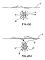
- Figures 4a and 4b are sectional views respectively of first and second types of tracking controller;
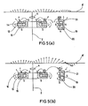
- Figures 5a and 5b are sectional views respectively of a combination of tracking and focussing controller in accordance with the present invention and of a known combination of a focussing and tracking controller;
- Figure 6 shows a plan view of an optical focus position control device;
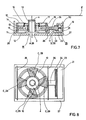
- Figure 7 shows a sectional view of an optical focus position control device in accordance with the present invention incorporating a first means for properly dealing with damping;
- Figure 8 shows a plan view of an optical focus position control device in accordance with the present invention incorporating a second means for properly dealing with damping characteristics;
- Figure 9 also shows a plan view of an optical focus position control device in accordance with the present invention incorporating a third means for properly dealing with the damping characteristics; and
- Figure 10 also shows a plan view of an optical focus position control device in accordance with the present invention incorporating a fourth means for properly dealing with the damping characteristics.
- In Figure 1,
symbol 1 denotes a laser beam source that emitslaser beams 2.Symbol 3 denotes a mirror, andsymbol 4 denotes an objective lens that causes thelaser beams 2 to be focussed onto the recording medium surface of a disc.Symbol 5 denotes an optical focus position control device that causes the optical focus position to be accurately positioned with respect to the tracks of the recording medium of a disc by driving anobjective lens 4 either in the vertical (up/down) or horizontal (left/right) direction. Symbol 6 denotes an optical head that contains all the optical devices mentioned above.Symbol 7 denotes a recording/erasing coil that applies a magnetic field to the surface of the disc recording medium while either recording or erasing information.Symbol 8 denotes an optical disc incorporating a disc recording medium 8', andsymbol 9 denotes a motor that drives said optical disc to rotate. - The focus control to be performed by said optical focus
position control device 5, i.e., a fine adjustment of the incident laser beam focus position in order to deal with the disc displacement in the direction of the incident laser beam axis, can be achieved by causing theobjective lens 4 to move in the direction of the thickness of saidoptical disc 8. On the other hand, the tracking control to be performed by said optical focusposition control device 5, i.e., a fine adjustment of the incident laser beam focus position in order to deal with the disc displacement in the radial direction, can be performed by causing theobjective lens 4 to move in the radial direction of theoptical disc 8. - First, the focus controller will be described. In Figure 2
symbol 10 denotes a lens-mirror cylinder containing and supporting anobjective lens 4, where said lens-mirror cylinder 10 is installed in aholder 11 in such a way that it can be vertically moved due to theelastic material 12 which is deflectable in the direction of the axis of the incident laser beam. -
Symbol 13 denotes a focussing permanent magnet,symbol 14 denotes a focussing yoke plate, andsymbol 15 denotes a focussing yoke, which are all securely attached to theholder 11. Together, these three elements make up a closed magnetic circuit including amagnetic space 16 between said focussingyoke plate 14 and focussingyoke 15.Symbol 17 denotes a focus driving coil, which is attached to the lens-mirror cylinder and crosses saidmagnetic space 16. If the focus control current is fed to saidfocus driving coil 17, magnetism will be generated in saidcoil 17, and as a result, due to interaction with the magnetism generated by the focussingpermanent magnet 13, thefocus driving coil 17, lens-mirror cylinder 10, and theobjective lens 4, will be displaced in the direction of the incident laser beam axis. These elements make up thefocus controller 18. - The structure of the tracking controller will now be described.
Symbol 19 denotes a permanent magnet,symbol 20 denotes a yoke plate andsymbol 21 denotes a yoke available for the tracking operation. These elements are securely attached to a stationary holder (not illustrated) that fully supports the optical focus position control device. Together these make up a closed magnetic circuit which includes amagnetic space 22 between saidyoke plate 20 andyoke 21.Symbol 23 denotes a radial driving coil, which is securely fixed onto the radialdrive coil holder 24 and crosses saidmagnetic space 22. As shown in the drawing, said radialdrive coil holder 24 is connected to thefocus controller 18. Since thefocus controller 18 is movable in the radial direction due to elastic material (not illustrated), if the tracking control current is fed to saidradial drive coil 23, magnetism will be generated by saidcoil 23, and as a result, due to interaction with the magnetism generated by thepermanent magnet 19 that is used for the tracking operation, thefocus controller 18 will be displaced in the radial direction. These elements make up the trackingcontroller 25. - A variety of means are provided for effectively preventing the leakage magnetism of the optical focus position control device, comprising said
focus controller 18, and trackingcontroller 25, from causing adverse effects on therecording medium 8 of the optical disc. Such means are described below:- - Figure 3b shows a sectional view of a focus controller of the kind as disclosed in Japanese patent publication No. 57-113431. Symbols N and S respectively denote the north and south poles. As shown in Figure 3a, the focus controller provides the
magnetic space 16 available for the focussing operation in an area close to the optical disc. This construction minimises leakage magnetism that would otherwise adversely affect the recording medium 8' of the optical disc. The leakage magnetism will significantly affect the surface of the recording medium 8' of the optical disc if saidmagnetic space 16 for the focussing operation is provided in an area remote from the optical disc as shown in Figure 3b. The length of each arrow in Figures 3a and 3b respectively denotes the intensity of the leakage magnetism at the moment when the focussing operation has just started while the direction of the leakage magnetism is shown by the direction of the arrows. -
- The tracking controller of Figure 4a provides the
permanent magnet 19 available for the tracking operation in the centre of the closed magnetic circuit. This construction minimises leakage magnetism that would otherwise adversely affect the recording medium 8' of the optical disc. In a construction where the permanent magnet 19' available for the tracking operation is provided encircling the closed magnetic circuit, if the magnitude of the magnetic field that functions in the magnetic space 22' is designed to be equal to that in themagnetic space 22 of Figure 4a available for the tracking operation, the leakage magnetism will significantly affect the surface of the recording medium 8' of the optical disc. - Figure 5a shows sectional views of both the focussing and tracking controllers in a combination incorporating improvements in accordance with the present invention, whereas Figure 5b shows sectional views of both the focussing and tracking controllers in a combination which does not incorporate such improvements. As shown in Figure 5a, both the focussing and tracking controllers with the improved means are set in positions close to each other, and the magnetic poles of the focussing
yoke plate 14 and of the trackingyoke 21 which are the portions of the closed magnetic circuits of the focussing and tracking controllers which are both closest to each other and disposed to be closest to the disc, are of the same polarity i.e., poles N and N face each other, as shown in Figure 5a. On the other hand, the example shown in Figure 5b illustrates that the magnetic poles of the focussing and tracking controllers which do not incorporate the Fig 5a improvement are set in positions close to each other, but the magnetic poles of the focussingyoke plate 14 which is set close to the optical disc, and the trackingyoke 21 are of the opposite polarity, i.e., poles N and S face each other. In this case, the magnitude of the leakage magnetism adversely affecting the surface of the recording medium 8' of the optical disc is double the leakage magnetism in the device shown in Figure 5a. - In addition to the improved constructions described above, any adverse effect of the leakage magnetism on the surface of the recording medium 8' of the optical disc can be reduced further by additionally providing the following means including (a) a construction that provides a highly permeable magnetic substance such as permalloy in a position facing the optical disc of the optical focus position control device, (b) a construction that includes the entire optical focus position control device in said highly permeable magnetic substance, (c) a construction that includes a holder made of said highly permeable magnetic substance for supporting the entire optical focus position control device, and (d) a construction that includes both the focussing and tracking controllers within said highly permeable magnetic substance.
- Figure 6 shows a plan view of the optical focus position control device shown in Figure 2. As shown in the drawing, an objective
lens mirror cylinder 10 is provided in such a way that it can be moved only in the dual axes directions, i.e., either in the vertical (up/down) or horizontal (left/right) directions since it is supported by the vertically workableelastic material 12 that moves in the focussing direction and by the horizontally workableelastic material 26 that moves in the radial direction. This construction prevents the objective lens from even the slightest incline. - A focussing
drive coil 17 is provided in such a way that it can only move in the direction across the focussingmagnetic space 16, while aradial drive coil 23 is provided so that it can only move in the direction across the trackingmagnetic space 22. As a result, the magnetic space necessary for both the focussing and tracking operations can be extremely narrow, and so the electromagnetic force is used very effectively. This allows the size of the permanent magnet to be significantly reduced, and as a result, an extremely compact optical focus control device can be achieved. - Next, the movement characteristics of both the focussing and tracking controllers of the
objective lens 10 will be described below:- - As shown in Figures 2 and 6, the focussing controller is driven by the electromagnetic effect which results from the interaction between the focussing closed magnetic circuit secured to the
interim holder 11, and the focussingdrive coil 17 secured to the objectivelens mirror cylinder 10. - Said
interim holder 11 and the objectivelens mirror cylinder 10 are connected to each other via elastic material that is moveable only in the vertical direction i.e. in the direction of focussing, for instance byparallel spring 12 that can be moved in the direction of focussing. - Assuming that the weight of the movable part in the direction of focussing which includes the
objective lens 4, objectivelens mirror cylinder 10, and the drivingcoil 17 for focussing operation is MF, and the vertical spring constant of theparallel spring 12 moving in the direction of focussing is KF, then the vertical movement of the objectivelens mirror cylinder 10 will have a resonance frequency which is represented by the formula
When a driving force for the focussing operation is provided by the induced electromagnetic force, the phase delay in the movement for a displacement XF of theobjective lens mirror 10 in the focussing direction varies from 0° to 90° when 0 < f < fF, (where f (Hz) represents a frequency) whereas the delay will vary from 90° to 180° when fF < f, and it will be exactly 180° when fF << f. As a result, if the focussing target position is YF, by advancing the phase of the signal representing the focussing drive force FF by means of a phase advancing compensation circuit, the movement phase delay for the displacement XF of the focus direction moving part can be adjusted to any desired level below 180°. This ensures very stable focus control operation. - As shown in Figures 2 and 6, the tracking controller is driven by the electromagnetic effect that results from the interaction between the closed magnetic circuit secured to the
stationary holder 27 and thetracking drive coil 23 on the trackingdrive coil holder 24 which is secured to theinterim holder 11. Saidstationary holder 27 and theinterim holder 11 are connected to each other by elastic material that is movable only to the left and to the right, i.e. in the radial direction, for instance by aparallel spring coupling 26 that moves in the direction of the disc radius. Assuming that the weight of the focussingcontroller 18 is MT and the spring constant of theparallel spring 26 moving in the direction of the disc radius is KT, then the radial movement of the objectivelens mirror cylinder 10 will have a resonance frequency (hereinafter called the primary resonance frequency) fT which is represented by the formula
Theinterim holder 11 and the objectivelens mirror cylinder 10 are connected to each other by theparallel spring coupling 12 which moves in the direction of focussing. However, thisparallel spring 12 will move to the left and to the right to a certain extent due to its elasticity. Thus, assuming that the spring constant of the focus directionparallel spring 12 is K'F when it moves in a radial direction and it causes the objectivelens mirror cylinder 10 to move to the left and right, the spring will have a resonance frequency (hereinafter called the secondary resonance frequency) represented by
As described above, whenever the objectivelens mirror cylinder 10 moves to the left and right, both primary and secondary resonance frequencies will occur. Note that the spring constant K'F of the parallel spring that moves in the focussing direction is significantly large when the spring moves to the left and right, i.e. K'F >> KT. This means that the secondary resonance frequency f'T is significantly higher than the primary resonance frequency fT, i.e. f'T >> fT. When the tracking drive force FT is generated by the induced electromagnetic force mentioned above with a frequency denoted by f, the movement phase delay in the displacement XT of the objectivelens mirror cylinder 10 in the tracking direction varies from 0° to 90° when 0 < f < fT, or from 90° to 270° when fT < f < f'T, or from 270° to 360° when f'T < f. - When the tracking drive force FT is generated, the phase delay in the movement in the displacement ST of the objective
lens mirror cylinder 10 moving to the tracking target position YT should remain below 180° throughout the frequency band of the tracking control signal. As described earlier, even if the phase advancing compensation circuit is used to advance the phase of the tracking drive signal FT, since there is a certain limit for advancing the phase amount, the phase cannot be compensated for in order that it can exceed 180° significantly. In order to properly compensate for the phase delay, the second resonance frequency f'T should be at an optimum level above the frequency band of the tracking control signal. Although the frequency band used for the tracking control signal can vary, generally an optical disc apparatus uses frequencies within therange 1 to 4 KHz. Experiment has shown that consequently the secondary resonance frequency f'T should be set at a level of above 8KHz. Means for designing a construction that fully satisfies the above conditions are described below. - As described above, the secondary resonance frequency f'T depends on the spring constant K'F of the
parallel spring 12 when it moves to the left and right and on the weight MF of the parts which move in the focussing direction. Since there is a limit to the amount by which the weight of theobjective lens 4 and thelens mirror cylinder 10 can be reduced, the weight MF of the part moving in the focussing direction cannot be decreased significantly. (Normally, said weight MF is in the range 0.5 to 10 grams). However, the greater the spring constant K'F, the greater the secondary resonance frequency f'T will be. The inventors followed up trials for increasing the spring constant K'F of theparallel spring 12 during its movement to the left and right. - The spring constant K'F was found to be given by

when theparallel spring 12 has a width XF and a thickness YF. As a result, it is clear that the spring constant K'F in the horizontal direction (left/right) can be increased by increasing the width XF and decreasing the thickness YF of saidparallel spring 12. In the light of the relationship given by
the secondary resonance frequency f'T can be obtained from the equation
It was found that theparallel spring 12 moving in the horizontal direction (left/right) should be designed so that it has a thickness of 20 to 50 microns and a width of 50 to 100 times the reference width YF. If theparallel spring 12 can be correctly designed in accordance with the findings described above, the phase delay of the movement of displacement XT of theobjective lens 4 relative to the tracking target position can be decreased below 180° within the frequency bands available for the tracking control signal. It is important that the phase advancing compensation circuit be used for correctly compensating for the movement phase delay. - According to the results of the trials undertaken by the inventors, very stable focussing and tracking controls were actually achieved by using a
parallel spring 12 made from beryllium-copper alloy having between 30 and 50 microns thickness. Nevertheless, since there are two kinds of the resonance frequencies, fF and fT, if the damping characteristics in the directions of focussing and tracking control remain negligible, the resonance multiple factor in said resonance frequencies will increase, thus readily causing interference vibration to occur during either the focussing or tracking control operation. Also, when a certain frequency above the resonance frequency level is reached, the phase delay in responding to the displacement of the movable parts will be at a value very close to 180°, which will result in an extremely unstable optical focus position control operation. To prevent this and ensure a satisfactory amount of damping the following means are provided:- - Figure 7 shows a sectional view of the optical focus position control device. As shown in the drawing, damping material 28 is held in a space A between the objective
lens mirror cylinder 10 and the focussingyoke 15, thus increasing the damping in the focussing direction. Further damping material 28 is held in a space B between the trackingdrive coil holder 24 and thestationary holder 27, thus increasing the damping in the direction of the tracking. To make up said damping material 28, viscose-elastic materials such as silicon rubber, butyl rubber, silicon-butyl rubber, and acrylicethylene rubber, foaming synthetic resin such as foamed polyurethane, and viscose fluid such as silicon grease, can be used. - Figure 8 shows a plan view of the optical focus position control device incorporating a second means of damping.
-
Parallel spring 12, which moves in the direction of focus, has a structure that connects two concentric circles, whereby two flat sheet springs, each being connected to four arms at the edges, are provided one in each of the upper and lower positions (See Figure 2). Saidparallel spring 12 moving in the direction of focus causes the objectivelens mirror cylinder 10 to move only in the vertical direction relative to the position of theinterim holder 11. Dampingmaterial 29 is bonded to the portions C of the surface of saidparallel spring 12, where the largest amount of the relative displacement exists, thus resulting in greater damping characteristics in the direction of focus. To make up said dampingmaterial 29, viscoseelastic materials such as silicon-rubber, butyl rubber, silicon-butyl rubber, and acrylic-ethylene rubber, and foaming synthetic resin such as foamed polyurethane, can be used. - Figure 9 shows a plan view of the optical focus position control device incorporating a third means of damping. Said damping
material 29 is bonded to the portions C of the surface of theparallel spring 12, where the largest amount of the relative displacement exists. The dampingmaterial 29 is connected to theparallel spring 12 at the edges C1 and C2. Viscose fluid such as silicon grease is charged in the portion C3 located between the edges C1 and C2, thus increasing the damping characteristics in the direction of focus. - Figure 10 shows a plan view of the optical focus position control device incorporating a fourth means of damping. The parallel springs 26 which move in the tracking direction are secured to the interim holder 11 (See Figure 2) at the centre, whilst also being secured to the
stationary holder 27 at both ends. First, one end D is secured to thestationary holder 27, and then the other end E is inserted into a slit 30 of thestationary holder 27, and finally viscose fluid 31 such as silicon grease is charged into said slit 30 to complete the installation of each saidparallel spring 26. - In addition to the means described above, there are a variety of other useful means for achieving increased damping such as making up either the focus direction or tracking direction movable parallel springs using vibration-proof alloy such as manganese-copper alloy, ferro-aluminum alloy, nickel-titanium alloy, magnesium alloy, etc. It is also useful to make up said springs by coating latexed acrylicethylene rubber over both surfaces of either the focus direction or tracking direction moving parallel spring. (Note that, if a sheet rubber is bonded to a metal spring by an adhesive agent such as primer, it will disadvantageously cause the spring to become stiff and the spring constant to increase).
- A wide variety of useful means for effectively increasing the damping characteristics have been described above. However, the damping characteristics can be improved further by combining the above means.
- The embodiments of the invention thus described with reference to the accompanying drawings will obviously be suggestive of derivations and modifications. For example, the focussing and/or tracking means can be applied to any head positioning device for a recording disc, the head being used for recording, playing back or erasing information or for performing any combination of these functions.
- Reference is hereby directed to European patent 0115666 from which this present application is divided and to copending European patent application No. 88119198.5 which is also divided from European patent 0115666.
Claims (14)
- An optical focus position control device for an optical disc apparatus that records, plays back, and/or erases information on a recording medium (8) which includes a magnetic film by irradiation of said magnetic film with an optical beam, such as a laser beam (2), said optical focus position control device comprising a focussing controller operable to move the position of the optical focus of the beam in the focussing direction, that is in a direction transverse to the film, and a tracking controller (19 - 24) operable to move said position of the optical focus of the beam in the tracking direction, that is in a direction parallel to the film;
the focussing controller having focussing electromagnetic drive means (13 - 17) which comprises:
a first closed magnetic circuit which includes a permanent magnet (13), a first yoke plate (14), a yoke (15) and a magnetic space (16) between said first yoke plate (14) and yoke (15), and;
a drive coil (17) arranged to move in said magnetic space;
and said tracking controller having tracking electromagnetic drive means which comprises:
a second closed magnetic circuit independent of the first closed magnetic circuit which includes a permanent magnet (19), a second yoke plate (20), a yoke (21) and a magnetic space (22) between said second yoke plate (20) and yoke (21), and:
a drive coil (23) arranged to move in said magnetic space (22);
characterised in that respective portions (14, 21) of the first and second closed magnetic circuits of the focussing and tracking electromagnetic drive means which are both closest to each other and disposed to be closest to the film are of the same magnetic polarity. - An optical focus position controlling device according to claim 1 wherein said respective portions are portions of the focussing controller yoke plate (14) and of the tracking controller yoke (21), respectively.
- An optical focus controlling device according to claim 1 or claim 2 wherein said focussing controller includes an intermediate holder (11) and is mounted with respect to a stationary holder (27) by way of a first parallel spring coupling (26) arranged to allow movement of the focussing controller relative to the stationary holder in the tracking direction, said tracking electromagnetic drive means being coupled to drive the intermediate holder in the tracking direction relative to the stationary holder.
- An optical focus position controlling device according to claim 3 characterised in that said first parallel spring coupling comprises a pair of parallel springs each comprising a metal spring element and latex rubber attached to the surface of said metal spring element.
- An optical focus position controlling device according to claim 4 wherein said latex rubber is a latex acrylic-ethylene rubber.
- An optical focus position controlling device according to claim 5 wherein each said metal spring element of said first parallel spring coupling is made of a vibration-proof alloy.
- An optical focus position control device according to claim 3 characterised in that said first parallel spring coupling comprises a pair of parallel springs made of a vibration-proof alloy.
- An optical focus position control device according to any of claims 3 to 7 wherein there is provided an objective lens (4) by which the optical beam is focussed and a cylindrical holder (10) in which the objective lens is mounted, said cylindrical holder being coupled to the intermediate holder (11) by way of a second parallel spring coupling (12) arranged to allow movement of the cylindrical holder relative to the intermediate holder in the focussing direction, said focussing electromagnetic drive means being coupled to drive the cylindrical holder in the focussing direction relative to the intermediate holder.
- An optical focus position controlling device according to claim 8 characterised in that said second parallel spring coupling comprises a pair of parallel springs each comprising a metal spring element and latex rubber attached to the surface of said metal spring element.
- An optical focus position controlling device according to claim 9 wherein said latex rubber is a latex acrylic-ethylene rubber.
- An optical focus position controlling device according to claim 9 or claim 10 wherein each said metal spring element of said second parallel spring coupling is made of a vibration-proof alloy.
- An optical focus position controlling device according to claim 8 characterised in that said second parallel spring coupling comprises a pair of parallel springs made of a vibration-proof alloy.
- An optical focus position controlling device according to claim 3, further including elastic material (29) bonded to said first parallel spring coupling for improving the damping characteristics thereof.
- An optical focus position controlling device according to claim 8, further including elastic material bonded to said second parallel spring coupling for improving the damping characteristics thereof.
Priority Applications (1)
| Application Number | Priority Date | Filing Date | Title |
|---|---|---|---|
| EP19880119199 EP0318772B1 (en) | 1983-01-25 | 1983-09-15 | Optical focus position control device |
Applications Claiming Priority (7)
| Application Number | Priority Date | Filing Date | Title |
|---|---|---|---|
| JP1103783A JPS59139154A (en) | 1983-01-25 | 1983-01-25 | Device for controlling position of light focusing |
| JP11037/83 | 1983-01-25 | ||
| JP68770/83 | 1983-04-18 | ||
| JP6877083A JPS59193551A (en) | 1983-04-18 | 1983-04-18 | Controller for light focusing position |
| JP69619/83 | 1983-04-19 | ||
| JP6961983A JPS59195336A (en) | 1983-04-19 | 1983-04-19 | Controller for light condensing position |
| EP19880119199 EP0318772B1 (en) | 1983-01-25 | 1983-09-15 | Optical focus position control device |
Related Parent Applications (2)
| Application Number | Title | Priority Date | Filing Date |
|---|---|---|---|
| EP83305435A Division-Into EP0115666B1 (en) | 1983-01-25 | 1983-09-15 | Optical focus position control in optical disc apparatus |
| EP83305435.6 Division | 1983-09-15 |
Publications (2)
| Publication Number | Publication Date |
|---|---|
| EP0318772A1 EP0318772A1 (en) | 1989-06-07 |
| EP0318772B1 true EP0318772B1 (en) | 1992-06-10 |
Family
ID=27441471
Family Applications (1)
| Application Number | Title | Priority Date | Filing Date |
|---|---|---|---|
| EP19880119199 Expired EP0318772B1 (en) | 1983-01-25 | 1983-09-15 | Optical focus position control device |
Country Status (1)
| Country | Link |
|---|---|
| EP (1) | EP0318772B1 (en) |
Families Citing this family (1)
| Publication number | Priority date | Publication date | Assignee | Title |
|---|---|---|---|---|
| IT1248120B (en) * | 1991-01-25 | 1995-01-05 | Bruno Castellan | LAYER TRANSLATOR-POSITIONER GROUP |
Family Cites Families (3)
| Publication number | Priority date | Publication date | Assignee | Title |
|---|---|---|---|---|
| US4410277A (en) * | 1978-11-01 | 1983-10-18 | Hitachi, Ltd. | Apparatus for detecting magneto-optical anisotropy |
| GB2060927B (en) * | 1979-07-24 | 1984-02-01 | Universal Pioneer Corp | Signal reading device for optical discs |
| NL8006183A (en) * | 1979-11-12 | 1981-06-01 | Nippon Telegraph & Telephone | RECORDING DEVICE FOR USE IN VIDEO AND / OR AUDIO INFORMATION READING DEVICES. |
-
1983
- 1983-09-15 EP EP19880119199 patent/EP0318772B1/en not_active Expired
Also Published As
| Publication number | Publication date |
|---|---|
| EP0318772A1 (en) | 1989-06-07 |
Similar Documents
| Publication | Publication Date | Title |
|---|---|---|
| US4660190A (en) | Optical focus position control in optical disc apparatus | |
| EP0122816B1 (en) | Optical focus position control in an optical memory system | |
| JP3154141B2 (en) | Buffer device and recording and / or reproducing device for disk-shaped recording medium using buffer device | |
| EP0115666B1 (en) | Optical focus position control in optical disc apparatus | |
| JPH04102232A (en) | Objective lens driving device and optical disk device | |
| JPH08273177A (en) | Optical system driving device | |
| EP0333601A2 (en) | Objective lens support and positioning system | |
| KR100362215B1 (en) | Lens shifter (without yoke bridge) | |
| EP0318772B1 (en) | Optical focus position control device | |
| EP0314200B1 (en) | Optical focus position control device | |
| CA1219073A (en) | Optical focus position control in an optical memory system | |
| US5901133A (en) | Objective lens actuator | |
| JPH06301995A (en) | Information recording and/or reader | |
| JPS6243256B2 (en) | ||
| JP2621200B2 (en) | Objective lens actuator | |
| JPS6284437A (en) | Drive device for objective lens | |
| JPH0756696B2 (en) | Light focusing position controller | |
| JPS63181133A (en) | Objective lens driver | |
| JPH03154235A (en) | Actuator | |
| JPS6173248A (en) | Objective lens driving device of optical recorder and reproducing device | |
| JPH03113839A (en) | Objective lens driving device | |
| JP2720557B2 (en) | Objective lens drive | |
| JP2685840B2 (en) | Objective lens drive | |
| JPS6289245A (en) | Objective lens driver | |
| JPS6127811B2 (en) |
Legal Events
| Date | Code | Title | Description |
|---|---|---|---|
| PUAI | Public reference made under article 153(3) epc to a published international application that has entered the european phase |
Free format text: ORIGINAL CODE: 0009012 |
|
| AC | Divisional application: reference to earlier application |
Ref document number: 115666 Country of ref document: EP |
|
| AK | Designated contracting states |
Kind code of ref document: A1 Designated state(s): DE FR GB IT |
|
| 17P | Request for examination filed |
Effective date: 19890704 |
|
| 17Q | First examination report despatched |
Effective date: 19901018 |
|
| GRAA | (expected) grant |
Free format text: ORIGINAL CODE: 0009210 |
|
| AC | Divisional application: reference to earlier application |
Ref document number: 115666 Country of ref document: EP |
|
| AK | Designated contracting states |
Kind code of ref document: B1 Designated state(s): DE FR GB IT |
|
| ITF | It: translation for a ep patent filed |
Owner name: BUGNION S.P.A. |
|
| REF | Corresponds to: |
Ref document number: 3382580 Country of ref document: DE Date of ref document: 19920716 |
|
| ET | Fr: translation filed | ||
| PLBE | No opposition filed within time limit |
Free format text: ORIGINAL CODE: 0009261 |
|
| STAA | Information on the status of an ep patent application or granted ep patent |
Free format text: STATUS: NO OPPOSITION FILED WITHIN TIME LIMIT |
|
| 26N | No opposition filed | ||
| REG | Reference to a national code |
Ref country code: GB Ref legal event code: IF02 |
|
| PGFP | Annual fee paid to national office [announced via postgrant information from national office to epo] |
Ref country code: FR Payment date: 20020910 Year of fee payment: 20 |
|
| PGFP | Annual fee paid to national office [announced via postgrant information from national office to epo] |
Ref country code: GB Payment date: 20020911 Year of fee payment: 20 |
|
| PGFP | Annual fee paid to national office [announced via postgrant information from national office to epo] |
Ref country code: DE Payment date: 20020918 Year of fee payment: 20 |
|
| PG25 | Lapsed in a contracting state [announced via postgrant information from national office to epo] |
Ref country code: GB Free format text: LAPSE BECAUSE OF EXPIRATION OF PROTECTION Effective date: 20030914 |
|
| REG | Reference to a national code |
Ref country code: GB Ref legal event code: PE20 |