EP0318725A1 - Thermal transfer type color recording method - Google Patents
Thermal transfer type color recording method Download PDFInfo
- Publication number
- EP0318725A1 EP0318725A1 EP88118523A EP88118523A EP0318725A1 EP 0318725 A1 EP0318725 A1 EP 0318725A1 EP 88118523 A EP88118523 A EP 88118523A EP 88118523 A EP88118523 A EP 88118523A EP 0318725 A1 EP0318725 A1 EP 0318725A1
- Authority
- EP
- European Patent Office
- Prior art keywords
- ink film
- paper
- transfer paper
- recording
- ink
- Prior art date
- Legal status (The legal status is an assumption and is not a legal conclusion. Google has not performed a legal analysis and makes no representation as to the accuracy of the status listed.)
- Granted
Links
Images


Classifications
-
- B—PERFORMING OPERATIONS; TRANSPORTING
- B41—PRINTING; LINING MACHINES; TYPEWRITERS; STAMPS
- B41J—TYPEWRITERS; SELECTIVE PRINTING MECHANISMS, i.e. MECHANISMS PRINTING OTHERWISE THAN FROM A FORME; CORRECTION OF TYPOGRAPHICAL ERRORS
- B41J35/00—Other apparatus or arrangements associated with, or incorporated in, ink-ribbon mechanisms
- B41J35/16—Multicolour arrangements
- B41J35/18—Colour change effected automatically
-
- B—PERFORMING OPERATIONS; TRANSPORTING
- B41—PRINTING; LINING MACHINES; TYPEWRITERS; STAMPS
- B41J—TYPEWRITERS; SELECTIVE PRINTING MECHANISMS, i.e. MECHANISMS PRINTING OTHERWISE THAN FROM A FORME; CORRECTION OF TYPOGRAPHICAL ERRORS
- B41J17/00—Mechanisms for manipulating page-width impression-transfer material, e.g. carbon paper
- B41J17/02—Feeding mechanisms
- B41J17/12—Special adaptations for ensuring maximum life
Definitions
- the present invention relates to a thermal transfer color recording method and an apparatus therefor, and more particularly to a method of and an apparatus for recording color images on transfer paper with use of a single thermal head by successively transferring inks of different colors from an ink film to the paper.
- the disclosed method employs an ink film having ink layers arranged in succession and different from one another in color (e.g. yellow, magenta and cyan).
- the ink film and transfer paper in intimate contact therewith are transported in one direction relative to a thermal head.
- the ink film is transported in the same direction as for recording to position the next ink layer of another color as opposed to the thermal head, while the transfer paper having the ink of the first color transferred thereto is transported in a direction opposite to the direction for recording to position the leading end of the recording area thereof again in opposed relation to the thermal head.
- the main object of the present invention is to provide a thermal transfer color recording method for producing satisfactory color images and an apparatus for practicing this method.
- Another object of the invention is to provide a thermal transfer color recording method and an apparatus therefor wherein after recording with an in of a color has been completed, the transfer paper and the ink film can be transported in different directions without producing great frictional resistance therebetween.
- thermal transfer color recording method with use of an ink film and transfer paper comprising transporting the transfer paper in the same direction as for recording, with ink film not taken up, after recording with an ink of a color has been completed, to thereby slacken the ink film, thereafter transporting the transfer paper in a direction opposite to the direction for recording.
- the objects are filfilled also by an apparatus for practicing this method.
- the ink film is transported as opposed to a non-recorded area of the transfer paper other than the recorded area thereof after recording has been completed with an ink of the color.
- Fig. 1 is a diagram schematically showing the construction of a thermal transfer color printer embodying the invention.
- the printer includes a tractor feeder 1 and a platen roller 2 around which elongated transfer paper P extends. At the position where the transfer paper P is in contact with the platen roller 2, the paper P comes into contact with an ink film F extending from a feed roll 3 to a takeup roll 4. At the position where the paper F and the film F are in contact with each other, inks on the ink film F are transferred onto the paper P by a thermal head 5 disposed on the rear side of the film F, whereby images are recorded on the paper P.
- the diagram further shows a guide roller 7 for stabilizing the tension on the ink film F, and a separating roller 8 for moving the ink film F out of intimate contact with the transfer paper P after recording. Disposed in the vicinity of the separating roller 8 is a sensor 9 for detecting marks SY, SM and SC (Fig. 2) indicating the colors of the ink film F.
- the tractor feeder 1 which is coupled to a stepping motor M1, operates to transport the paper P in two directions, i.e., forward (direction of arrow a ) and reversely (direction of arrow b ).
- the amount and direction of transport of the transfer paper P are controlled by changing the number and polarity of pulses to be given to the stepping motor M1.
- the takeup roll 4 is coupled to a stepping motor M2 through a one-way clutch 10 for transporting the ink film F only in the direction of arrow c .
- the amount of transport of the ink film F is controlled by varying the number of pulses to be given to the stepping motor M2.
- the one-way clutch 10 transmits a drive force from the motor M2 to the takeup roll 4 for transporting the ink film F in the direction of arrow c but does not transmit any reverse torque.
- a slip clutch or the like is used as the one-way clutch 10 so that an excessive torque, even if acting in the film transport direction c, will not break the ink film F.
- the one-way clutch 10 gives constant tension to the ink film F at all times, thus permitting the takeup roll 4 to wind up the film reliably.
- the thermal head 5 is pivotally movable between a position where the head 5 presses the transfer paper P and the ink film F against the platen roller 2 and a position away from the platen roller 2.
- An eccentric cam 11 in contact with a portion of the thermal head 5 is provided for pressing the thermal head 5 against the platen roller 2 or moving the head away from the roller 2.
- the eccentric cam 11 is driven by a rotary solenoid 14 (Fig. 3).
- a multiplicity of heating elements mounted on the thermal head 5 and arranged in a direction parallel to the axis of the platen roller 2 are selectively driven, whereby the ink is transferred from the ink film F to the transfer paper P.
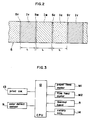
- the ink film F is in the form of a strip having approximately the same width as the transfer paper P and is provided thereon with ink layers IY, IM and IC of three colors, i.e., yellow, magenta and cyan, having a specified length L.
- the ink film F has the color indicating marks SY, SM and SC preceding the respective ink layers IY, IM and IC with respect to the direction of transport of the film.
- the marks SY, SM and SC indicate the colors of the respective following ink layers and are detectable by the color sensor 9.
- Fig. 3 is a block diagram showing the control circuit of the thermal transfer color printer.
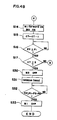
- the printer is controlled in its entirety by a CPU 12 which has connected thereto a print switch 13, the color sensor 9, the motors M1 and M2, the thermal head 5, and the rotary solenoid 14 for pivotally moving the thermal head 5.
- step S1 When depression of the print switch 13 is detected (step S1), the stepping motor M1 is energized to start transporting the ink film F (step S2). In this state, the thermal head 5 is away from the platen roller 2.
- a counter CT is reset to "0" (step S4), and the motor M2 is deenergized to discontinue transport of the ink film.
- the counter CT is advanced every time an image is recorded in each of the colors, yellow, magenta and cyan. At this time, the leading end of a recording area RA of the transfer paper P where the image is to be recorded is positioned at a distance of L2 + L5 away from the thermal head 5 upstream thereof with respect to the direction of advance of the paper P as seen in Fig.
- step S6 To position the leading end of the recording area RA in opposed relation with the thermal head 5, the stepping motor Ml is therefore energized to start advancing the paper P (step S6). Subsequently,the number of pulses PP given to the stepping motor M1 becomes equal to the sum of pulse numbers P2 and P5 for transporting the paper P by a distance L2 and distance L5, respectively (step S7), whereupon the motor M1 is deenergized to discontinue the transport of the paper P.
- step S9 the yellow ink layer IY of the ink film F and the recording area RA of the paper P are both positioned as opposed to the thermal head 5, whereupon the thermal head 5 is pressed against the platen roller 2 (step S9).
- Recording data for one line is transferred to the thermal head 5 (step S10) to drive heating elements individually according to the recording data and thereby record an image portion for one line (step S11).
- a predetermined number of pulses are then fed to each of the stepping motors M1 and M2 to advance both the paper P and the ink film F in synchronism by one line (step S12).
- the one-line recording operation of steps S10 to S12 is repeatedly conducted until the contemplated image is completely recorded in the recording area RA for every line.
- both the stepping motors M1, M2 are energized to advance the paper P and the film F in intimate contact therewith in synchronism (step S14), and the counter CT is advanced by an increment of 1 (step S15).
- the number of pulses PP given to the stepping motor M2 then reaches a pulse number F1 for transporting the film F by a distance L1 from the position opposed to the thermal head 5 to a position where the film is separated from the paper P by the separating roller 8 (step S16), whereupon the counter CT is checked as to whether the count is smaller than "3".
- step S18 the stepping moror M2 is deenergized (step S18), with the stepping motor M1 held energized, advancing the paper P. Consequently, with the thermal head 5 pressed against the platen roller 2, the ink film F in intimate contact with the transfer paper P is transported not by the torque of the stepping motor M2 but only by the movement of the paper P.
- the number of pulses PP given to the stepping motor M1 in step S14 and the following steps then reaches a pulse number (P1 + P3) required for transporting the paper P by the distance L1 plus a specified distance L3 (step S19), whereupon the thermal head 5 is released from the platen roller 2 (step S20).
- the ink film F has been forwarded by contact with the paper P with the stepping motor M2 held unenergized and therefore slackens in the vicinity of the separating roller 8 without being wound up on the takeup roll 4 (see Fig. 7).
- the stepping motor M1 is brought into reverse rotation to start transporting the paper P reversely in the direction of arrow b (step S21).
- the number of pulses PP given to the stepping motor M1 reaches a pulse number (P0 + P1 + P2 + P3) needed for a nonrecording area of the paper P, which is away from the leading end of the recording area RA by the distance L2 upstream thereof, to retract to the position opposed to the thermal head 5 (step S22), whereupon the stepping motor M1 is deenergized (step S23).
- the pulses, P0 in number are those given to the stepping motor M1 for transporting the paper P by a distance corresponding to the length L0 of the recording area RA along the direction of transport.
- the stepping motor M2 is energized to start transporting the ink film F (step S24) for recording an image in the magenta ink.
- the stepping motor M2 is deenergized to discontinue the transport of the film F (step S26).
- the stepping motor M1 is energized (step S27). The number of pulses PP given to the motor then reaches the pulse number P2 required for transporting the paper P by the distance L2 (step S28), whereupon the motor M1 is deenergized (step S29).
- step S17 When the recording in cyan is completed, the count of the counter CT is "3". This is confirmed in step S17, which is then followed by step S30 to turn off the stepping motor M2 which is energized after the completion of cyan recording.
- the thermal head 5 is released from the platen roller 2 in step S31.
- the number of pulses PP given to the stepping motor M1 after the cyan recording then reaches a pulse number (P1 + P3 + P4) for discharging the transfer paper P from the printer (step S32), whereupon the motor M1 is deenergized (step S33).
- the pulse number P4 is set to a desired value for transporting the paper P excessively by a distance L4 to discharge the paper from the printer after recording in all colors has been completed.
- the transfer paper P only is advanced with the stepping motor M2 for transporting the ink film F held deenergized after the completion of recording in yellow as well as in magenta to thereby slacken the ink film F, whereupon the paper P is transported in the reverse direction. Accordingly, the paper P can be transported reversely with reduced frictional resistance between the paper P and the ink film F since the film F is not tensioned.
- the ink film F is transported as opposed to the nonrecording area of the transfer paper P for the color sensor 9 to detect the marks SY, SM and SC provided for the respective ink layers on the film F, with the result that the ink already transferred onto the paper P is precluded from coming into contact with the ink on the film F.
- Investigation of the frictional resistance between the transfer paper and the ink film we made has revealed that when the ink on the ink film is brought into contact with the ink transferred to the paper, the frictional resistance acting between the two ink portions is exceedingly great, whereas when the ink film is transported as opposed to the nonrecording area of the transfer paper as in the present embodiment, the frictional resistance can be substantially diminished.
- the transfer paper used in the foregoing embodiment is a strip of paper in the form of a roll
- cut sheets cf paper are also usable.
- d.c. motors are usable in place of the stepping motors employed in the above embodiment as drive means for transporting the transfer paper and the ink film.
- the rotation of the d.c. motor is not controllable by varying the number of pulses, there is a need to use an encoder, timer or the like for controlling the amount of rotation of the motor.
- the ink film used for the above embodiment has yellow, magenta and cyan ink layers, a black ink layer may be formed on the film in addition to these ink layers, or an entirely different combination of colors may be used. These ink layers of different colors can be arranged in an optional order.
Abstract
Description
- The present invention relates to a thermal transfer color recording method and an apparatus therefor, and more particularly to a method of and an apparatus for recording color images on transfer paper with use of a single thermal head by successively transferring inks of different colors from an ink film to the paper.
- The thermal transfer color recording method mentioned above is disclosed in U.S.P. No. 4,505,603 (corresponding to Unexamined Japanese Patent Publication SHO 58-140270) and U.S.P. No. 4,642,656 (corresponding to Unexamined Japanese Patent Publication SHO 61-14973).
- The disclosed method employs an ink film having ink layers arranged in succession and different from one another in color (e.g. yellow, magenta and cyan). For recording, the ink film and transfer paper in intimate contact therewith are transported in one direction relative to a thermal head. After an image has been recorded in one color, the ink film is transported in the same direction as for recording to position the next ink layer of another color as opposed to the thermal head, while the transfer paper having the ink of the first color transferred thereto is transported in a direction opposite to the direction for recording to position the leading end of the recording area thereof again in opposed relation to the thermal head.
- When thus transported in directions opposite to each other, the transfer paper bearing the recorded image and the ink film are held in intimate contact with each other, so that the prior-art technique has the problem that the drive means are subjected to greatly varying loads due to the frictional resistance between the paper and the film. Consequently, the paper or the ink film becomes transported improperly to position the image of second color out of register with the image of first color. It is also likely that the transferred ink will be removed from the paper by friction.
- Accordingly, the main object of the present invention is to provide a thermal transfer color recording method for producing satisfactory color images and an apparatus for practicing this method.
- Another object of the invention is to provide a thermal transfer color recording method and an apparatus therefor wherein after recording with an in of a color has been completed, the transfer paper and the ink film can be transported in different directions without producing great frictional resistance therebetween.
- These objects are fulfilled by a thermal transfer color recording method with use of an ink film and transfer paper comprising transporting the transfer paper in the same direction as for recording, with ink film not taken up, after recording with an ink of a color has been completed, to thereby slacken the ink film, thereafter transporting the transfer paper in a direction opposite to the direction for recording. The objects are filfilled also by an apparatus for practicing this method.
- In another aspect of the present invention, the ink film is transported as opposed to a non-recorded area of the transfer paper other than the recorded area thereof after recording has been completed with an ink of the color.
- These and other objects or features of the present invention will become apparent from the following description of a preferred embodiment thereof taken in conjunction with the accompanying drawings, in which:
- Fig. 1 is a diagram showing a thermal transfer color printer embodying the invention;
- Fig. 2 is a diagram illustrating the form of an ink film for use in the printer;
- Fig. 3 is a block diagram showing a control circuit included in the embodiment;
- Figs. 4A to 4C and Fig. 5 are respectively flow charts and a time chart showing the recording operation of the embodiment;
- Fig. 6 is a diagram for illustrating the lengths of portions of transfer paper; and
- Fig. 7 is a diagram for illustrating the lengths of some of the portions along the periphery of a platen roller.
- In the following description, like parts are designated by like reference numbers throughout the several drawings.
- An embodiment of the invention will be described below.
- Fig. 1 is a diagram schematically showing the construction of a thermal transfer color printer embodying the invention.
- The printer includes a
tractor feeder 1 and a platen roller 2 around which elongated transfer paper P extends. At the position where the transfer paper P is in contact with the platen roller 2, the paper P comes into contact with an ink film F extending from afeed roll 3 to a takeup roll 4. At the position where the paper F and the film F are in contact with each other, inks on the ink film F are transferred onto the paper P by athermal head 5 disposed on the rear side of the film F, whereby images are recorded on the paper P. The diagram further shows a guide roller 7 for stabilizing the tension on the ink film F, and aseparating roller 8 for moving the ink film F out of intimate contact with the transfer paper P after recording. Disposed in the vicinity of theseparating roller 8 is asensor 9 for detecting marks SY, SM and SC (Fig. 2) indicating the colors of the ink film F. - The
tractor feeder 1, which is coupled to a stepping motor M1, operates to transport the paper P in two directions, i.e., forward (direction of arrow a) and reversely (direction of arrow b). The amount and direction of transport of the transfer paper P are controlled by changing the number and polarity of pulses to be given to the stepping motor M1. - The takeup roll 4 is coupled to a stepping motor M2 through a one-
way clutch 10 for transporting the ink film F only in the direction of arrow c. The amount of transport of the ink film F is controlled by varying the number of pulses to be given to the stepping motor M2. The one-way clutch 10 transmits a drive force from the motor M2 to the takeup roll 4 for transporting the ink film F in the direction of arrow c but does not transmit any reverse torque. A slip clutch or the like is used as the one-way clutch 10 so that an excessive torque, even if acting in the film transport direction c, will not break the ink film F. The one-way clutch 10 gives constant tension to the ink film F at all times, thus permitting the takeup roll 4 to wind up the film reliably. - The
thermal head 5 is pivotally movable between a position where thehead 5 presses the transfer paper P and the ink film F against the platen roller 2 and a position away from the platen roller 2. An eccentric cam 11 in contact with a portion of thethermal head 5 is provided for pressing thethermal head 5 against the platen roller 2 or moving the head away from the roller 2. The eccentric cam 11 is driven by a rotary solenoid 14 (Fig. 3). When thethermal head 5 is pressed against the platen roller 2, a multiplicity of heating elements mounted on thethermal head 5 and arranged in a direction parallel to the axis of the platen roller 2 are selectively driven, whereby the ink is transferred from the ink film F to the transfer paper P. - With reference to Fig. 2, the ink film F is in the form of a strip having approximately the same width as the transfer paper P and is provided thereon with ink layers IY, IM and IC of three colors, i.e., yellow, magenta and cyan, having a specified length L. The ink film F has the color indicating marks SY, SM and SC preceding the respective ink layers IY, IM and IC with respect to the direction of transport of the film. The marks SY, SM and SC indicate the colors of the respective following ink layers and are detectable by the
color sensor 9. - Fig. 3 is a block diagram showing the control circuit of the thermal transfer color printer. The printer is controlled in its entirety by a
CPU 12 which has connected thereto aprint switch 13, thecolor sensor 9, the motors M1 and M2, thethermal head 5, and therotary solenoid 14 for pivotally moving thethermal head 5. - The recording operation of the color printer will be described below with reference to the flow charts of Figs. 4A to 4C and the time chart of Fig. 5.
- When depression of the
print switch 13 is detected (step S1), the stepping motor M1 is energized to start transporting the ink film F (step S2). In this state, thethermal head 5 is away from the platen roller 2. Upon thecolor sensor 9 detecting the yellow mark SY, a counter CT is reset to "0" (step S4), and the motor M2 is deenergized to discontinue transport of the ink film. The counter CT is advanced every time an image is recorded in each of the colors, yellow, magenta and cyan. At this time, the leading end of a recording area RA of the transfer paper P where the image is to be recorded is positioned at a distance of L2 + L5 away from thethermal head 5 upstream thereof with respect to the direction of advance of the paper P as seen in Fig. 6. To position the leading end of the recording area RA in opposed relation with thethermal head 5, the stepping motor Ml is therefore energized to start advancing the paper P (step S6). Subsequently,the number of pulses PP given to the stepping motor M1 becomes equal to the sum of pulse numbers P2 and P5 for transporting the paper P by a distance L2 and distance L5, respectively (step S7), whereupon the motor M1 is deenergized to discontinue the transport of the paper P. - In this way, the yellow ink layer IY of the ink film F and the recording area RA of the paper P are both positioned as opposed to the
thermal head 5, whereupon thethermal head 5 is pressed against the platen roller 2 (step S9). Recording data for one line is transferred to the thermal head 5 (step S10) to drive heating elements individually according to the recording data and thereby record an image portion for one line (step S11). A predetermined number of pulses are then fed to each of the stepping motors M1 and M2 to advance both the paper P and the ink film F in synchronism by one line (step S12). The one-line recording operation of steps S10 to S12 is repeatedly conducted until the contemplated image is completely recorded in the recording area RA for every line. - When the recording in the yellow ink has been completed in all lines of the recording area RA (step S13), both the stepping motors M1, M2 are energized to advance the paper P and the film F in intimate contact therewith in synchronism (step S14), and the counter CT is advanced by an increment of 1 (step S15). The number of pulses PP given to the stepping motor M2 then reaches a pulse number F1 for transporting the film F by a distance L1 from the position opposed to the
thermal head 5 to a position where the film is separated from the paper P by the separating roller 8 (step S16), whereupon the counter CT is checked as to whether the count is smaller than "3". If the count is smaller than "3", indicating that recording in all the three colors has not been completed, the stepping moror M2 is deenergized (step S18), with the stepping motor M1 held energized, advancing the paper P. Consequently, with thethermal head 5 pressed against the platen roller 2, the ink film F in intimate contact with the transfer paper P is transported not by the torque of the stepping motor M2 but only by the movement of the paper P. The number of pulses PP given to the stepping motor M1 in step S14 and the following steps then reaches a pulse number (P1 + P3) required for transporting the paper P by the distance L1 plus a specified distance L3 (step S19), whereupon thethermal head 5 is released from the platen roller 2 (step S20). The ink film F has been forwarded by contact with the paper P with the stepping motor M2 held unenergized and therefore slackens in the vicinity of the separatingroller 8 without being wound up on the takeup roll 4 (see Fig. 7). - After the ink film F has been thus slackened, the stepping motor M1 is brought into reverse rotation to start transporting the paper P reversely in the direction of arrow b (step S21). During the reverse transport, the number of pulses PP given to the stepping motor M1 reaches a pulse number (P0 + P1 + P2 + P3) needed for a nonrecording area of the paper P, which is away from the leading end of the recording area RA by the distance L2 upstream thereof, to retract to the position opposed to the thermal head 5 (step S22), whereupon the stepping motor M1 is deenergized (step S23). The pulses, P0 in number, are those given to the stepping motor M1 for transporting the paper P by a distance corresponding to the length L0 of the recording area RA along the direction of transport.
- After the nonrecording area of the transfer paper P has been thus brought to the position where it is opposed to the
thermal head 5, i.e., the position where the area comes into contact with the ink film F, the stepping motor M2 is energized to start transporting the ink film F (step S24) for recording an image in the magenta ink. Upon thecolor sensor 9 detecting the magenta mark SM (step S25), the stepping motor M2 is deenergized to discontinue the transport of the film F (step S26). Subsequently, to position the leading end of the recording area RA of the paper P in opposed relation with thethermal head 5, the stepping motor M1 is energized (step S27). The number of pulses PP given to the motor then reaches the pulse number P2 required for transporting the paper P by the distance L2 (step S28), whereupon the motor M1 is deenergized (step S29). - In this way, the leading end of the recording area RA already bearing the yellow record is registered with the leading end of the magental ink layer IM at the position opposed to the
thermal head 5, and the same procedure as the foregoing steps S9 to S29 is executed to produce a magenta record. After the completion of recording in magenta, the same steps as steps S9 to S16 are repeated to produce a cyan record. Consequently, a color image is formed in the recording area with the three color inks. - When the recording in cyan is completed, the count of the counter CT is "3". This is confirmed in step S17, which is then followed by step S30 to turn off the stepping motor M2 which is energized after the completion of cyan recording. The
thermal head 5 is released from the platen roller 2 in step S31. The number of pulses PP given to the stepping motor M1 after the cyan recording then reaches a pulse number (P1 + P3 + P4) for discharging the transfer paper P from the printer (step S32), whereupon the motor M1 is deenergized (step S33). The pulse number P4 is set to a desired value for transporting the paper P excessively by a distance L4 to discharge the paper from the printer after recording in all colors has been completed. - With the thermal transfer color printer embodying the invention and described above, the transfer paper P only is advanced with the stepping motor M2 for transporting the ink film F held deenergized after the completion of recording in yellow as well as in magenta to thereby slacken the ink film F, whereupon the paper P is transported in the reverse direction. Accordingly, the paper P can be transported reversely with reduced frictional resistance between the paper P and the ink film F since the film F is not tensioned.
- Further with the present embodiment, the ink film F is transported as opposed to the nonrecording area of the transfer paper P for the
color sensor 9 to detect the marks SY, SM and SC provided for the respective ink layers on the film F, with the result that the ink already transferred onto the paper P is precluded from coming into contact with the ink on the film F. Investigation of the frictional resistance between the transfer paper and the ink film we made has revealed that when the ink on the ink film is brought into contact with the ink transferred to the paper, the frictional resistance acting between the two ink portions is exceedingly great, whereas when the ink film is transported as opposed to the nonrecording area of the transfer paper as in the present embodiment, the frictional resistance can be substantially diminished. - With the frictional resistance between the paper and the ink film thus diminished, both the paper and the film can be transported with good stability to afford satisfactory color images.
- Although the transfer paper used in the foregoing embodiment is a strip of paper in the form of a roll, cut sheets cf paper are also usable. In this case, however, there arises a need to provide in place of the tractor feeder a pair of paper transport rollers at each of the upstream side and downstream side of the platen roller with respect to the direction of transport of the sheet for handling the paper sheet, and to control the amount and direction of rotation of the rollers. It is also necessary to provide guide plates defining the path of transport of the paper sheet.
- Furthermore, d.c. motors are usable in place of the stepping motors employed in the above embodiment as drive means for transporting the transfer paper and the ink film. However, since the rotation of the d.c. motor is not controllable by varying the number of pulses, there is a need to use an encoder, timer or the like for controlling the amount of rotation of the motor.
- Although the ink film used for the above embodiment has yellow, magenta and cyan ink layers, a black ink layer may be formed on the film in addition to these ink layers, or an entirely different combination of colors may be used. These ink layers of different colors can be arranged in an optional order.
- Although the present invention has been fully described by way of example with reference to the accompanying drawings, it is to be noted that various changes and modifications will be apparent to those skilled in the art. Therefore, unless otherwise such changes and modifications depart from the scope of the present invention, they should be construed as being included therein.
Claims (2)
a first step of transferring a ink of one color from the ink film to the transfer paper based on image to be recorded, while transporting the ink film and the transfer paper through the recording station in a forward direction in intimate contact with each other and taking up the ink film past the recording station;
a second step of transporting the transfer paper in intimate contact with the ink film in the forward direction with the ink film not taken up to thereby slacken the ink film;
a third step of transporting the transfer paper in the reverse direction to position the leading end of recorded area of the transfer paper at the recording station; and
a fourth step of transferring a ink of another color from the ink film to the transfer paper from the leading end of recorded area thereof based on image to be recorded, while transporting the ink film and the transfer paper through the recording station in the forward direction in intimate contact with each other and taking up the ink film past the recording station.
ink film supply means for supplying the ink film past the recording station;
ink film take-up means for taking up the ink film supplied by said supply means;
a platen located at the recording station;
a thermal head located adjacent said platen;
paper transport means for transporting the transfer paper in forward and reverse directions through the recording station between said thermal head and said platen; and
control means for controlling said ink film take-up means and paper transport means, after completion of recording with an ink of one color, so as to move the transfer paper in intimate contact with the ink film in the forward direction with ink film take-up means turned off to thereby slacken the ink film, and thereafter to move the transfer paper in the reverse direction to position the leading end of recorded area of the transfer paper at the recording station.
Applications Claiming Priority (4)
| Application Number | Priority Date | Filing Date | Title |
|---|---|---|---|
| JP280309/87 | 1987-11-07 | ||
| JP280308/87 | 1987-11-07 | ||
| JP28030887 | 1987-11-07 | ||
| JP28030987 | 1987-11-07 |
Publications (2)
| Publication Number | Publication Date |
|---|---|
| EP0318725A1 true EP0318725A1 (en) | 1989-06-07 |
| EP0318725B1 EP0318725B1 (en) | 1992-04-15 |
Family
ID=26553716
Family Applications (1)
| Application Number | Title | Priority Date | Filing Date |
|---|---|---|---|
| EP88118523A Expired - Lifetime EP0318725B1 (en) | 1987-11-07 | 1988-11-07 | Thermal transfer type color recording method |
Country Status (3)
| Country | Link |
|---|---|
| US (1) | US4943812A (en) |
| EP (1) | EP0318725B1 (en) |
| DE (1) | DE3870169D1 (en) |
Families Citing this family (3)
| Publication number | Priority date | Publication date | Assignee | Title |
|---|---|---|---|---|
| US5172989A (en) * | 1989-12-14 | 1992-12-22 | Minolta Camera Kabushiki Kaisha | Thermal transfer color printer with tensioning roller |
| US5399031A (en) * | 1993-02-25 | 1995-03-21 | Eastman Kodak Company | Assisting movement of dye receiver past thermal print head |
| TWI426025B (en) * | 2011-04-21 | 2014-02-11 | Hiti Digital Inc | Thermal sublimation printer capable of cutting print media precisely and printing method using same |
Citations (2)
| Publication number | Priority date | Publication date | Assignee | Title |
|---|---|---|---|---|
| US4505603A (en) * | 1982-02-16 | 1985-03-19 | Tokyo Shibaura Denki Kabushiki Kaisha | Thermal transfer color printer and a method relating thereto |
| US4642656A (en) * | 1984-12-27 | 1987-02-10 | Minolta Camera Kabushiki Kaisha | Thermal printer |
Family Cites Families (3)
| Publication number | Priority date | Publication date | Assignee | Title |
|---|---|---|---|---|
| JPS599084A (en) * | 1982-07-09 | 1984-01-18 | Shinko Electric Co Ltd | Thermal multi-color printer |
| JPS5983687A (en) * | 1982-11-02 | 1984-05-15 | Seiko Instr & Electronics Ltd | Heat-sensitive transfer type multicolor printer |
| JPS61219158A (en) * | 1985-03-25 | 1986-09-29 | Mitsubishi Electric Corp | Manufacture of semiconductor device |
-
1988
- 1988-11-04 US US07/267,536 patent/US4943812A/en not_active Expired - Fee Related
- 1988-11-07 DE DE8888118523T patent/DE3870169D1/en not_active Expired - Fee Related
- 1988-11-07 EP EP88118523A patent/EP0318725B1/en not_active Expired - Lifetime
Patent Citations (2)
| Publication number | Priority date | Publication date | Assignee | Title |
|---|---|---|---|---|
| US4505603A (en) * | 1982-02-16 | 1985-03-19 | Tokyo Shibaura Denki Kabushiki Kaisha | Thermal transfer color printer and a method relating thereto |
| US4642656A (en) * | 1984-12-27 | 1987-02-10 | Minolta Camera Kabushiki Kaisha | Thermal printer |
Non-Patent Citations (2)
| Title |
|---|
| PATENT ABSTRACTS OF JAPAN, vol. 11, no. 158 (M-591)[2605], 22nd May 1987; & JP-A-61 291 158 (FUJITSU LTD) 20-12-1986 * |
| PATENT ABSTRACTS OF JAPAN, vol. 8, no. 195 (M-323)[1632], 7th September 1984; & JP-A-59 83 687 (SEIKO DENSHI KOGYO K.K.) 15-05-1984 * |
Also Published As
| Publication number | Publication date |
|---|---|
| DE3870169D1 (en) | 1992-05-21 |
| US4943812A (en) | 1990-07-24 |
| EP0318725B1 (en) | 1992-04-15 |
Similar Documents
| Publication | Publication Date | Title |
|---|---|---|
| US4532525A (en) | Image forming device | |
| EP0673776B1 (en) | Printer for supplying continuous paper to printing portion | |
| JPS599084A (en) | Thermal multi-color printer | |
| US4771296A (en) | Transfer ribbon feed arrangement | |
| US4863297A (en) | Thermal printer | |
| US5083879A (en) | Image recording apparatus | |
| US4943812A (en) | Thermal transfer type color recording method and apparatus therefor | |
| JPS6410981B2 (en) | ||
| JPS63104862A (en) | Thermal transfer recorder | |
| US5585835A (en) | Thermal printer having dual receiver transport paths | |
| JPH02535A (en) | Thermal transfer color printer | |
| JPS5911278A (en) | Color thermal printer | |
| JP3359767B2 (en) | Thermal transfer recording device | |
| JPS59215873A (en) | Thermal transfer type printing method | |
| JPH08300697A (en) | Thermal transfer recording apparatus and ink sheet feed device | |
| JPH05278285A (en) | Thermal printer | |
| JP3321484B2 (en) | Multicolor thermal transfer recording device | |
| JPH04348982A (en) | Recorder | |
| CA1299232C (en) | Transfer ribbon feed arrangement | |
| GB2224975A (en) | Multi-colour transfer ribbon feed arrangement detecting | |
| US5476329A (en) | Printing method and apparatus for thermal transfer printer | |
| JP2576564B2 (en) | Thermal transfer printing method | |
| JP2611526B2 (en) | Color thermal transfer recording device | |
| JPH02206575A (en) | Printing device | |
| JPH0443065A (en) | Ink ribbon for color hard copy |
Legal Events
| Date | Code | Title | Description |
|---|---|---|---|
| PUAI | Public reference made under article 153(3) epc to a published international application that has entered the european phase |
Free format text: ORIGINAL CODE: 0009012 |
|
| AK | Designated contracting states |
Kind code of ref document: A1 Designated state(s): DE FR GB |
|
| 17P | Request for examination filed |
Effective date: 19890802 |
|
| 17Q | First examination report despatched |
Effective date: 19901122 |
|
| GRAA | (expected) grant |
Free format text: ORIGINAL CODE: 0009210 |
|
| AK | Designated contracting states |
Kind code of ref document: B1 Designated state(s): DE FR GB |
|
| ET | Fr: translation filed | ||
| REF | Corresponds to: |
Ref document number: 3870169 Country of ref document: DE Date of ref document: 19920521 |
|
| PLBE | No opposition filed within time limit |
Free format text: ORIGINAL CODE: 0009261 |
|
| STAA | Information on the status of an ep patent application or granted ep patent |
Free format text: STATUS: NO OPPOSITION FILED WITHIN TIME LIMIT |
|
| 26N | No opposition filed | ||
| REG | Reference to a national code |
Ref country code: FR Ref legal event code: CD |
|
| PGFP | Annual fee paid to national office [announced via postgrant information from national office to epo] |
Ref country code: GB Payment date: 19991103 Year of fee payment: 12 |
|
| PGFP | Annual fee paid to national office [announced via postgrant information from national office to epo] |
Ref country code: DE Payment date: 19991108 Year of fee payment: 12 |
|
| PGFP | Annual fee paid to national office [announced via postgrant information from national office to epo] |
Ref country code: FR Payment date: 19991109 Year of fee payment: 12 |
|
| PG25 | Lapsed in a contracting state [announced via postgrant information from national office to epo] |
Ref country code: GB Free format text: LAPSE BECAUSE OF NON-PAYMENT OF DUE FEES Effective date: 20001107 |
|
| GBPC | Gb: european patent ceased through non-payment of renewal fee |
Effective date: 20001107 |
|
| PG25 | Lapsed in a contracting state [announced via postgrant information from national office to epo] |
Ref country code: FR Free format text: LAPSE BECAUSE OF NON-PAYMENT OF DUE FEES Effective date: 20010731 |
|
| PG25 | Lapsed in a contracting state [announced via postgrant information from national office to epo] |
Ref country code: DE Free format text: LAPSE BECAUSE OF NON-PAYMENT OF DUE FEES Effective date: 20010801 |
|
| REG | Reference to a national code |
Ref country code: FR Ref legal event code: ST |