EP0318156A2 - Apparatus and method for the disposal of contaminated or dangerous articles - Google Patents
Apparatus and method for the disposal of contaminated or dangerous articles Download PDFInfo
- Publication number
- EP0318156A2 EP0318156A2 EP88310131A EP88310131A EP0318156A2 EP 0318156 A2 EP0318156 A2 EP 0318156A2 EP 88310131 A EP88310131 A EP 88310131A EP 88310131 A EP88310131 A EP 88310131A EP 0318156 A2 EP0318156 A2 EP 0318156A2
- Authority
- EP
- European Patent Office
- Prior art keywords
- container
- closure member
- hollow
- article
- receiving means
- Prior art date
- Legal status (The legal status is an assumption and is not a legal conclusion. Google has not performed a legal analysis and makes no representation as to the accuracy of the status listed.)
- Withdrawn
Links
Images
Classifications
-
- A—HUMAN NECESSITIES
- A61—MEDICAL OR VETERINARY SCIENCE; HYGIENE
- A61M—DEVICES FOR INTRODUCING MEDIA INTO, OR ONTO, THE BODY; DEVICES FOR TRANSDUCING BODY MEDIA OR FOR TAKING MEDIA FROM THE BODY; DEVICES FOR PRODUCING OR ENDING SLEEP OR STUPOR
- A61M5/00—Devices for bringing media into the body in a subcutaneous, intra-vascular or intramuscular way; Accessories therefor, e.g. filling or cleaning devices, arm-rests
- A61M5/178—Syringes
- A61M5/31—Details
- A61M5/32—Needles; Details of needles pertaining to their connection with syringe or hub; Accessories for bringing the needle into, or holding the needle on, the body; Devices for protection of needles
- A61M5/3205—Apparatus for removing or disposing of used needles or syringes, e.g. containers; Means for protection against accidental injuries from used needles
-
- A—HUMAN NECESSITIES
- A61—MEDICAL OR VETERINARY SCIENCE; HYGIENE
- A61B—DIAGNOSIS; SURGERY; IDENTIFICATION
- A61B50/00—Containers, covers, furniture or holders specially adapted for surgical or diagnostic appliances or instruments, e.g. sterile covers
- A61B50/30—Containers specially adapted for packaging, protecting, dispensing, collecting or disposing of surgical or diagnostic appliances or instruments
- A61B50/36—Containers specially adapted for packaging, protecting, dispensing, collecting or disposing of surgical or diagnostic appliances or instruments for collecting or disposing of used articles
- A61B50/362—Containers specially adapted for packaging, protecting, dispensing, collecting or disposing of surgical or diagnostic appliances or instruments for collecting or disposing of used articles for sharps
Definitions
- This invention relates to an apparatus and method for the disposal of contaminated or dangerous articles such as needles, (called “sharps”) which have been used for the giving of injections or taking blood.
- the syringes have been disposed of separately to the sharps, for example in a liquid impermeable bin to retain any liquid which may leak from the syringes.
- Known used sharps containers suffer from the disadvantage that they can be overfilled thereby presenting a risk to any person placing a further used sharp into the container.
- Acording to a first aspect of the invention we provide an apparatus for the disposal of a contaminated or dangerous article comprising a container, characterised in that the apparatus has a receiving means, the receiving means having a hollow to receive the article and a closure member movable from a closed position in which the article is prevented from passing from the hollow into the container, to an open position in which the article is able to pass from the hollow into the container, operating means which are operable externally of the container to move the closure member from the closed position to the open position, resilient means to return the closure member to the closed position when the operating means are released.
- the apparatus in accordance with the first aspect of the invention provides significant advantages over prior arrangements.
- an article such as a used sharp can be disposed of into the container simply by inserting the sharp into the hollow and then operating the operating means so that there is no risk of injury from any sharp already received in the container.
- the closure member opens in the same general direction in which the article moves to pass from the hollow into the container. This provides a third advantage in that as the container is filled, eventually the closure member is prevented from being opened, by articles already in the container, ensuring that the container cannot be overfilled.
- the container is made from a liquid impermeable material such as plastic, so that in the event that liquid for example from used syringes, leaks into the container, the container does not become weakened.
- a second aspect of the invention we provide a method of disposing of a contaminated or dangerous article using an apparatus in accordance with the first aspect of the invention, characterised in that the method comprises placing the article in the hollow to the receiving means, operating the operating means to cause the closure member to move to the open position and allow the article to pass into the container.
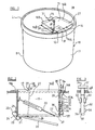
- FIGURE 1 is a side illustrative perspective view of an apparatus in accordance with the invention.
- FIGURE 2 is an illustrative plan view of part of the apparatus of Figure 1.
- FIGURE 3 is an end view of the part of the apparatus of Figure 2 taken on arrow A.
- an apparatus 10 for used sharps comprises a container 11 which in the example shown is of generally cylindrical configuration, but could be of another configuration as required.
- the container 11 has a lid L engaged with a body B in such a way e.g. snap interfit, that once engaged it is difficult or impossible to remove the lid L from the body B.
- the container 11 is made predominently in a plastic material, for example by moulding and is thus impermeable to the penetration of liquids.
- the container 11 has an opening 12 in the lid L thereof, the opening 12 receiving a receiving means 14 which is positioned therein.
- the receiving means 14 comprises a tube of generally rectangular cross section, although a tube of other cross section may be provided as required, each side of the rectangle having an outwardly extending flange 16 a , 16 b , 16 c , 16 d provided at one end of the tube 15.
- the flanges 16 a - 16 d are preferably adhered to the lid L but could alternatively have openings to receive fasteners such as rivets or screws, which engage with the lid L of the container 11 to secure the receiving means 14 in the position shown.
- the tube 15 defines an internal hollow 19 into which articles, in the present example, used syringes and sharps, one of which is shown at 20 in the hollow 19, can be placed.
- a closure member 22 is provided, the closure member 22 normally extending across the hollow 19 and preventing the syringe and sharp 20 from passing from the hollow 19 into the container 11.
- the closure member 22 is hinged to the tube wall via a hinge 23 which comprises a thin web of plastic material and thus the closure member 22 is pivotable about a hinge axis 24 from the closed position shown in dotted lines in figure 2, to the position shown in full lines.
- a resilient menas comprising a "C” spring 25 acts between abutments 21 on the closure member 22 and adjacent side of the receiving means 14, to retain the closure member 22 in the closed position, but the closure member 22 can be moved against the force of the resilient means 25 by an operating means.
- the operating means comprises a push rod 27 which is connected at a lower end 26 thereof to the closure member 22, the push rod 27 passing upwardly through an opening 17 in the flange 16 d to a push button or other manually engageable member 28.
- the closure member 22 and push rod 27 are all formed integrally with the remainder of the receiving means 14, in a generally flat condition as a plastic moulding.
- the receiving means 14 is then formed by scoring and bending the moulding to the required configuration.
- the opening 17 in flange 16 d to receive the push rod 27 may comprise a slot so that the push rod 27 is retained on three sides by the slot, and on the fourth side by a peripheral part of the opening 12 in the lid L.
- a locking formation 29 Adjacent the button 28, a locking formation 29 is provided which may be engaged with a corresponding hook formation 30 provided on flange 16 d when push rod 17 is depressed, and rotated, to maintain the closure member 22 in an open position if required.
- the push rod 27 When the container is full, the push rod 27 may be removed by twisting to break the connection between the lower end 26 of rod 27 and closure member 22 so that it is then necessary for further syringes and sharps 20 to be disposed of using a fresh empty apparatus 10.
- a locking means such as shown at 31 may be provided to lock the closure member 22 closed when the container is full.
- the locking means 31 comprises an elongate slider 32 which is held in the position shown in Figures 2 and 3, by a pair of formations 33 between which the slider 32 slides.
- the slider extends upwardly through an opening 17 a in flange 16 a (again a slot) to a manually engageable part 34 which has a step 35 which engages with flange 16 a to prevent the slider 32 being accidentally moved downwards.
- the slider 32 At its lower end, the slider 32 has a lug 35 which is received between a further, plain, pair of formations 36, and at its very lowest end, an inwardly extending flange 37 is provided.
- the closure member 22 is preferably made from a soft material so that in the event that in normal use anyone attempts to force a used sharp into the container 11 by pushing the closure member 22 open using the sharp, the sharp will simply dig in or pass through the closure member 22 without opening the closure member 22.
- the risk of a sharp breaking is minimised, but due to the depth of the hollow 19, even in the event that a sharp 20 were to break in the hollow 19, the break should be contained so that no part of the broken sharps leaves the hollow to present any risk of injury.
- the container 11 is generally cylindrical having a lid L although the container could extend upwardly to a neck in which the opening 12 is provided.
- the receiving means 14 or at least the tube 15 thereof, could be provided integrally within the lid L or neck of the container.
- the tube 15 could be of an alternative cross section to retangular as required e.g. circular, and can be fabricated and secured in the opening 12 in any manner desired.
- any other resilient means normally to urge the closure member 22 to the closed position could be provided, and the closure member 22 could in an alternative arrangement, be otherwise hinged relative to the tube 15 or be otherwise secured relative thereto and be openable from the closed to the open position.
- any other desired operating means operable from externally of the container, for moving the closure member 22 against the force of the resilient means 25 to allow articles to pass from the hollow 19 into the container may be provided e.g. a pull cord may be provided.
- the receiving means 15 can be manufactured from a generally flat sheet or moulding of suitable material, scored and folded to the configuration shown, or injection moulded to shape.
- the receiving means 14 may be moulded integrally with the lid L.
- the flanges 16 a -16 d which overlie the lid L may be continuous to provide a seal between the receiving means and the lid rather than having four flaps 16 a -16 d as described.
- the container 11 comprises a lid L and a body B so that bodies B can be stacked to facilate storage, although if desired, the lid L and body B may be provided integrally.
Abstract
An apparatus and method for the disposal of contaminated or dangerous articles such as needles (20), (called "sharps") which have been used for the giving of injections or taking of blood, the apparatus comprising a container (11), having a receiving means (14), the receiving means having a hollow (19) to receive the article (20) and a closure member (22) movable from a closed position in which the article is prevented from passing from the hollow into the container, to an open position in which the article is able to pass from the hollow into the container (11), operating means (27) which are operable externally of the container to move the closure member (22) from the closed position to the open position, resilient means (25) to return the closure member (22) to the closed position when the operating means are released.
Description
- This invention relates to an apparatus and method for the disposal of contaminated or dangerous articles such as needles, (called "sharps") which have been used for the giving of injections or taking blood.
- Previously it has been common medical practice to separate sharps from syringes after use and dispose of the used shaarps, in a container which has an opening through which the sharps are introduced into the container. Such containers are commonly made of cardboard to facilate incineration when full.
- The syringes have been disposed of separately to the sharps, for example in a liquid impermeable bin to retain any liquid which may leak from the syringes.
- Known used sharps containers suffer from the disadvantage that they can be overfilled thereby presenting a risk to any person placing a further used sharp into the container.
- Furthermore recently, it is has been medical practice not to separate the used sharps from their syringes prior to disposal because of the risk of injury this presents from the used sharp. It will be apparent that a used sharp could be contaminated with the blood of a patient suffering from an infectious disease such as Hepatitis or Aids, which disease could be transmitted in this way.
- Acording to a first aspect of the invention we provide an apparatus for the disposal of a contaminated or dangerous article comprising a container, characterised in that the apparatus has a receiving means, the receiving means having a hollow to receive the article and a closure member movable from a closed position in which the article is prevented from passing from the hollow into the container, to an open position in which the article is able to pass from the hollow into the container, operating means which are operable externally of the container to move the closure member from the closed position to the open position, resilient means to return the closure member to the closed position when the operating means are released.
- The apparatus in accordance with the first aspect of the invention provides significant advantages over prior arrangements.
- First, once the article is recieved in the container, it is not possible easily to remove the article, thereby overcoming the risk of, for example a drug addict, stealing a used sharp from a container.
- Secondly, an article such as a used sharp can be disposed of into the container simply by inserting the sharp into the hollow and then operating the operating means so that there is no risk of injury from any sharp already received in the container.
- Preferably the closure member opens in the same general direction in which the article moves to pass from the hollow into the container. This provides a third advantage in that as the container is filled, eventually the closure member is prevented from being opened, by articles already in the container, ensuring that the container cannot be overfilled.
- Preferably, the container is made from a liquid impermeable material such as plastic, so that in the event that liquid for example from used syringes, leaks into the container, the container does not become weakened.
- It will be appreciated that this provides a significant fourth advantage over cardboard containers which can become sodden with the ensuring risk that used sharps will be able to pass through the container wall and cause injury.
- According to a second aspect of the invention we provide a method of disposing of a contaminated or dangerous article using an apparatus in accordance with the first aspect of the invention, characterised in that the method comprises placing the article in the hollow to the receiving means, operating the operating means to cause the closure member to move to the open position and allow the article to pass into the container.
- The invention will now be described with the aid of the accompanying drawings in which:
- FIGURE 1 is a side illustrative perspective view of an apparatus in accordance with the invention.
- FIGURE 2 is an illustrative plan view of part of the apparatus of Figure 1.
- FIGURE 3 is an end view of the part of the apparatus of Figure 2 taken on arrow A.
- Referring to the drawings, an
apparatus 10 for used sharps comprises acontainer 11 which in the example shown is of generally cylindrical configuration, but could be of another configuration as required. - In this embodiment, the
container 11 has a lid L engaged with a body B in such a way e.g. snap interfit, that once engaged it is difficult or impossible to remove the lid L from the body B. - The
container 11 is made predominently in a plastic material, for example by moulding and is thus impermeable to the penetration of liquids. - The
container 11 has an opening 12 in the lid L thereof, the opening 12 receiving areceiving means 14 which is positioned therein. - The receiving
means 14 comprises a tube of generally rectangular cross section, although a tube of other cross section may be provided as required, each side of the rectangle having an outwardly extendingflange tube 15. Theflanges 16a - 16d are preferably adhered to the lid L but could alternatively have openings to receive fasteners such as rivets or screws, which engage with the lid L of thecontainer 11 to secure thereceiving means 14 in the position shown. - The
tube 15 defines aninternal hollow 19 into which articles, in the present example, used syringes and sharps, one of which is shown at 20 in the hollow 19, can be placed. - At the lower end of the
tube 15, aclosure member 22 is provided, theclosure member 22 normally extending across the hollow 19 and preventing the syringe and sharp 20 from passing from the hollow 19 into thecontainer 11. - The
closure member 22 is hinged to the tube wall via ahinge 23 which comprises a thin web of plastic material and thus theclosure member 22 is pivotable about ahinge axis 24 from the closed position shown in dotted lines in figure 2, to the position shown in full lines. - A resilient menas comprising a "C"
spring 25 acts betweenabutments 21 on theclosure member 22 and adjacent side of the receivingmeans 14, to retain theclosure member 22 in the closed position, but theclosure member 22 can be moved against the force of theresilient means 25 by an operating means. - The operating means comprises a
push rod 27 which is connected at alower end 26 thereof to theclosure member 22, thepush rod 27 passing upwardly through anopening 17 in the flange 16d to a push button or other manuallyengageable member 28. - Preferably, the
closure member 22 andpush rod 27 are all formed integrally with the remainder of thereceiving means 14, in a generally flat condition as a plastic moulding. Thereceiving means 14 is then formed by scoring and bending the moulding to the required configuration. Thus the opening 17 in flange 16d to receive thepush rod 27 may comprise a slot so that thepush rod 27 is retained on three sides by the slot, and on the fourth side by a peripheral part of the opening 12 in the lid L. - It will be appreciated that by pushing
rod 27 downwardly using thebutton 28, from outside thecontainer 11, theclosure member 22 will be moved from the closed position (dotted lines) to an open position (full lines) by pivoting about thehinge axis 24 the connevtion between therod 27 andmember 22 permitting thelower end 26 of therod 27 to pivot relative to themember 22. Thus anyarticle 20 placed in the hollow 19 of thereceiving means 14 will pass from the hollow 19 into thecontainer 11. - Adjacent the
button 28, alocking formation 29 is provided which may be engaged with acorresponding hook formation 30 provided on flange 16d whenpush rod 17 is depressed, and rotated, to maintain theclosure member 22 in an open position if required. - As the
container 11 is filled, it will be appreciated that the level of articles in the container will rise. Eventually, the articles will assume positions such that theclosure member 22 cannot be opened by operating the operating means, because theclosure member 22 moves in the same general direction that the articles must move to pass from the hollow 19 into the container. - Thus the container cannot be overfilled.
- When the container is full, the
push rod 27 may be removed by twisting to break the connection between thelower end 26 ofrod 27 andclosure member 22 so that it is then necessary for further syringes and sharps 20 to be disposed of using a freshempty apparatus 10. - If desired, a locking means such as shown at 31 may be provided to lock the
closure member 22 closed when the container is full. - The locking means 31 comprises an
elongate slider 32 which is held in the position shown in Figures 2 and 3, by a pair offormations 33 between which theslider 32 slides. The slider extends upwardly through an opening 17 a inflange 16a (again a slot) to a manuallyengageable part 34 which has astep 35 which engages withflange 16a to prevent theslider 32 being accidentally moved downwards. - At its lower end, the
slider 32 has alug 35 which is received between a further, plain, pair offormations 36, and at its very lowest end, an inwardly extendingflange 37 is provided. - When the
container 11 is full, and theclosure member 22 is closed, by depressing thepart 34, at the same time disengaging thestep 35 fromflange 16a, theslider 32 can be moved downwards until theflange 37 engages beneath theclosure member 22 as shown in dotted lines in figure 2 and thelug 35 engages in anopening 38 in theadjacent side wall 39 of the hollow 19. Thus theclosure member 22 cannot then be opened, and the locking means 30 cannot be released from outside thecontainer 11. - This is of course only one example of a locking means which may be provided, there being many alternative practical arrangements.
- The
closure member 22 is preferably made from a soft material so that in the event that in normal use anyone attempts to force a used sharp into thecontainer 11 by pushing theclosure member 22 open using the sharp, the sharp will simply dig in or pass through theclosure member 22 without opening theclosure member 22. Thus the risk of a sharp breaking is minimised, but due to the depth of the hollow 19, even in the event that a sharp 20 were to break in the hollow 19, the break should be contained so that no part of the broken sharps leaves the hollow to present any risk of injury. - Various modifications are possible without departing from the scope of the invention.
- As shown, the
container 11 is generally cylindrical having a lid L although the container could extend upwardly to a neck in which theopening 12 is provided. Alternatively, the receiving means 14 or at least thetube 15 thereof, could be provided integrally within the lid L or neck of the container. - The
tube 15 could be of an alternative cross section to retangular as required e.g. circular, and can be fabricated and secured in theopening 12 in any manner desired. - In place of the
spring 25 any other resilient means normally to urge theclosure member 22 to the closed position could be provided, and theclosure member 22 could in an alternative arrangement, be otherwise hinged relative to thetube 15 or be otherwise secured relative thereto and be openable from the closed to the open position. In place of the opening means comprising arod 27 any other desired operating means operable from externally of the container, for moving theclosure member 22 against the force of theresilient means 25 to allow articles to pass from the hollow 19 into the container, may be provided e.g. a pull cord may be provided. - As described, the receiving
means 15 can be manufactured from a generally flat sheet or moulding of suitable material, scored and folded to the configuration shown, or injection moulded to shape. - If desired, instead of the entire receiving means being moulded separately from the lid L, the
receiving means 14 may be moulded integrally with the lid L. - Where the receiving means is moulded, but separately from the lid, the
flanges 16a-16d which overlie the lid L may be continuous to provide a seal between the receiving means and the lid rather than having fourflaps 16a-16d as described. - As described, the
container 11 comprises a lid L and a body B so that bodies B can be stacked to facilate storage, although if desired, the lid L and body B may be provided integrally. - The features disclosed in the foregoing description in the following claims or the accompanying drawings, expressed in their specific forms or in terms of a means for performing the disclosed function, or a method or process for attaining the disclosed result, or a class or group of substances or compositions, as appropriate, may, separately or in any combination of such features, be utilised for realising the invention in diverse forms thereof.
Claims (10)
1. An apparatus (10) for the disposal of a contaminated or dangerous article (20) comprising a container (11), characterised in that the container has a receiving means (14), the receiving means having a hollow (19) to receive the article (20) and a closure member (22) movable from a closed position in which the article (20) is prevented from passing from the hollow (19) into the container (11), to an open position in which the article (20) is able to pass from the hollow (19) into the container (11), operating means (27) which are operable externally of the container (11) to move the closure member (23) from the closed position to the open position, resilient means (25) to return the closure member (22) to the closed position when the operating means (27) are released
2. An apparatus according to claim 1 characterised in that the closure member (22) opens in the same general direction in which the article (20) moves to pass from the hollow (19) into the container (11).
3. An apparatus according to claim 1 or claim 2 characterised in that means (31) are provided to lock the closure member (22) in a closed position.
4. An apparatus according to any one of the preceding claims characterised in that the container (11) is made from a liquid impermeable material.
5. An apparatus according to any one of the preceding claims characterised in that the receiving means (14) comprises a tube internally defining the hollow (19), the tube extending downwardly into the container (11) and having a sufficient length to support an article (20) placed in the hollow (19) with the article (20) temporarily supported by the closure member (22), the closure member (22) being at the bottom of the tube, and being hinged to the tube and movable by pivoting about a hinge axis (24) against the force of the resilient means (25).
6. An apparatus according to any one of the preceding characterised in that the resilient means (25) comprises a spring which is sufficiently strong to support the weight of an article (20) placed in the hollow (19) prior to operating of the operating means (27), and to return the closure member (22) to its closed position when the operating means (27) is released.
7. An apparatus according to any one of the preceding claims characterised in that the operating means (27) comprises a push rod which is attached to the closure member (22) and passes upwardly to a position adjacent the hollow (19) of the receiving means (14).
8. An apparatus according to any one of the preceding claims characterised in that the container (11) is generally cylindrical, the receiving means (14) being provided in an end face (L) of the cylinder, the hollow (19) of the receiving means (14) being spaced inwardly at least slightly from the side wall of the container (11).
9. An apparatus according to any one of the preceding claims characterised in that the container (11) comprises a body and a lid (L), the lid (L) being a snap fit with the body (B).
10. A method of disposing of a contaminated or dangerous article (20) using an apparatus (10) in accordance with any one of the preceding claims, characterised in that the method comprises placing the article (20) in the hollow (19) of the receiving means (14), operating the operating means (27) to cause the closure member (22) to move to the open position and allow the article (20) to pass into the container (11).
Applications Claiming Priority (2)
| Application Number | Priority Date | Filing Date | Title |
|---|---|---|---|
| GB878725246A GB8725246D0 (en) | 1987-10-28 | 1987-10-28 | Disposal of contaminated/dangerous articles |
| GB8725246 | 1987-10-28 |
Publications (2)
| Publication Number | Publication Date |
|---|---|
| EP0318156A2 true EP0318156A2 (en) | 1989-05-31 |
| EP0318156A3 EP0318156A3 (en) | 1989-07-26 |
Family
ID=10626033
Family Applications (1)
| Application Number | Title | Priority Date | Filing Date |
|---|---|---|---|
| EP88310131A Withdrawn EP0318156A3 (en) | 1987-10-28 | 1988-10-27 | Apparatus and method for the disposal of contaminated or dangerous articles |
Country Status (2)
| Country | Link |
|---|---|
| EP (1) | EP0318156A3 (en) |
| GB (2) | GB8725246D0 (en) |
Cited By (2)
| Publication number | Priority date | Publication date | Assignee | Title |
|---|---|---|---|---|
| CN105523325A (en) * | 2015-12-30 | 2016-04-27 | 王东宇 | Stirring-preventing dustbin |
| CN105600237A (en) * | 2015-12-30 | 2016-05-25 | 王东宇 | Anti-picking dustbin |
Families Citing this family (1)
| Publication number | Priority date | Publication date | Assignee | Title |
|---|---|---|---|---|
| GB2298126A (en) * | 1995-02-23 | 1996-08-28 | Andrew David Bartle | Waste bins |
Citations (3)
| Publication number | Priority date | Publication date | Assignee | Title |
|---|---|---|---|---|
| EP0080882A2 (en) * | 1981-11-26 | 1983-06-08 | William Rees Owen | Waste disposal bin |
| EP0221378A2 (en) * | 1984-03-01 | 1987-05-13 | Frontier Plastics (South Wales) Ltd. | Containers |
| EP0267776A2 (en) * | 1986-11-10 | 1988-05-18 | A.C. DANIELS & CO.,LTD., | Vessel for disposal of surgical waste |
Family Cites Families (2)
| Publication number | Priority date | Publication date | Assignee | Title |
|---|---|---|---|---|
| GB2087360B (en) * | 1980-11-19 | 1984-06-27 | Frontier Plastics South Wales | Disposal bin |
| GB8405390D0 (en) * | 1984-03-01 | 1984-04-04 | Frontier Plastics South Wales | Containers |
-
1987
- 1987-10-28 GB GB878725246A patent/GB8725246D0/en active Pending
-
1988
- 1988-10-27 EP EP88310131A patent/EP0318156A3/en not_active Withdrawn
- 1988-10-27 GB GB8825128A patent/GB2211487A/en not_active Withdrawn
Patent Citations (3)
| Publication number | Priority date | Publication date | Assignee | Title |
|---|---|---|---|---|
| EP0080882A2 (en) * | 1981-11-26 | 1983-06-08 | William Rees Owen | Waste disposal bin |
| EP0221378A2 (en) * | 1984-03-01 | 1987-05-13 | Frontier Plastics (South Wales) Ltd. | Containers |
| EP0267776A2 (en) * | 1986-11-10 | 1988-05-18 | A.C. DANIELS & CO.,LTD., | Vessel for disposal of surgical waste |
Cited By (2)
| Publication number | Priority date | Publication date | Assignee | Title |
|---|---|---|---|---|
| CN105523325A (en) * | 2015-12-30 | 2016-04-27 | 王东宇 | Stirring-preventing dustbin |
| CN105600237A (en) * | 2015-12-30 | 2016-05-25 | 王东宇 | Anti-picking dustbin |
Also Published As
| Publication number | Publication date |
|---|---|
| GB8825128D0 (en) | 1988-11-30 |
| GB2211487A (en) | 1989-07-05 |
| GB8725246D0 (en) | 1987-12-02 |
| EP0318156A3 (en) | 1989-07-26 |
Similar Documents
| Publication | Publication Date | Title |
|---|---|---|
| AU702942B2 (en) | Apparatus and methods for transporting and discarding medical materials | |
| US5630506A (en) | Apparatus and method for transporting and discarding medical materials | |
| US4886164A (en) | Containers for medical waste | |
| US4452358A (en) | Medical appliance disposal container | |
| AU685642B2 (en) | Burnable wastes collector with liquid absorber and identifier | |
| US5415315A (en) | Closure lid to disposable container for holding and disposing of used medical sharps and other medical-surgical materials | |
| US5167193A (en) | Medical wastes disposal system | |
| EP0611358B1 (en) | Sharps collector | |
| US5829588A (en) | Sharps container | |
| US5038929A (en) | Sharps disposal system | |
| US5511657A (en) | Container for disposing of hazardous medical waste | |
| US6283909B1 (en) | Container for supplying medical products and disposal of medical waste material | |
| US5163375A (en) | Medical wastes disposal system | |
| US4850507A (en) | Trash container with disposable bags | |
| US5323719A (en) | Contaminated wastes disposal system | |
| WO1996020880A1 (en) | Syringe sales and disposal box | |
| US5259501A (en) | Personal use syringe collecting and disposing system | |
| US20020100706A1 (en) | Sharps disposal | |
| EP0318156A2 (en) | Apparatus and method for the disposal of contaminated or dangerous articles | |
| GB2251423A (en) | A waste container | |
| US5201417A (en) | Disposable infectious waste container asssembly | |
| EP0267776A2 (en) | Vessel for disposal of surgical waste | |
| WO2002008073A1 (en) | Tamper proof hinged lid container | |
| WO1982000412A1 (en) | Disposal of needles | |
| JP2676530B2 (en) | Medical waste container |
Legal Events
| Date | Code | Title | Description |
|---|---|---|---|
| PUAI | Public reference made under article 153(3) epc to a published international application that has entered the european phase |
Free format text: ORIGINAL CODE: 0009012 |
|
| AK | Designated contracting states |
Kind code of ref document: A2 Designated state(s): AT BE CH DE ES FR GB GR IT LI LU NL SE |
|
| PUAL | Search report despatched |
Free format text: ORIGINAL CODE: 0009013 |
|
| RHK1 | Main classification (correction) |
Ipc: A61M 5/00 |
|
| AK | Designated contracting states |
Kind code of ref document: A3 Designated state(s): AT BE CH DE ES FR GB GR IT LI LU NL SE |
|
| STAA | Information on the status of an ep patent application or granted ep patent |
Free format text: STATUS: THE APPLICATION IS DEEMED TO BE WITHDRAWN |
|
| 18D | Application deemed to be withdrawn |
Effective date: 19900129 |