EP0317246A2 - Apparatus to develop an image on a sheet of developing paper - Google Patents
Apparatus to develop an image on a sheet of developing paper Download PDFInfo
- Publication number
- EP0317246A2 EP0317246A2 EP88310743A EP88310743A EP0317246A2 EP 0317246 A2 EP0317246 A2 EP 0317246A2 EP 88310743 A EP88310743 A EP 88310743A EP 88310743 A EP88310743 A EP 88310743A EP 0317246 A2 EP0317246 A2 EP 0317246A2
- Authority
- EP
- European Patent Office
- Prior art keywords
- roller
- sheet
- photo
- sheets
- sensitive material
- Prior art date
- Legal status (The legal status is an assumption and is not a legal conclusion. Google has not performed a legal analysis and makes no representation as to the accuracy of the status listed.)
- Granted
Links
- 238000003825 pressing Methods 0.000 claims abstract description 152
- 239000000463 material Substances 0.000 claims abstract description 115
- 230000002093 peripheral effect Effects 0.000 claims abstract description 93
- 230000033001 locomotion Effects 0.000 claims description 41
- 239000003094 microcapsule Substances 0.000 claims description 33
- 230000008933 bodily movement Effects 0.000 claims description 17
- 230000004044 response Effects 0.000 claims description 15
- 239000000126 substance Substances 0.000 claims description 11
- 238000005096 rolling process Methods 0.000 abstract description 10
- 239000000049 pigment Substances 0.000 description 24
- 239000002243 precursor Substances 0.000 description 21
- 238000009826 distribution Methods 0.000 description 15
- 230000018109 developmental process Effects 0.000 description 14
- 230000002829 reductive effect Effects 0.000 description 8
- 230000000694 effects Effects 0.000 description 7
- 230000001788 irregular Effects 0.000 description 7
- 239000003795 chemical substances by application Substances 0.000 description 6
- 238000006073 displacement reaction Methods 0.000 description 6
- 230000008901 benefit Effects 0.000 description 5
- 230000006835 compression Effects 0.000 description 4
- 238000007906 compression Methods 0.000 description 4
- 230000007246 mechanism Effects 0.000 description 4
- 230000009467 reduction Effects 0.000 description 4
- 230000004323 axial length Effects 0.000 description 3
- 210000000078 claw Anatomy 0.000 description 3
- 239000011248 coating agent Substances 0.000 description 3
- 238000000576 coating method Methods 0.000 description 3
- 239000012141 concentrate Substances 0.000 description 3
- 238000004519 manufacturing process Methods 0.000 description 3
- 239000002184 metal Substances 0.000 description 3
- 230000003252 repetitive effect Effects 0.000 description 3
- 239000011347 resin Substances 0.000 description 3
- 229920005989 resin Polymers 0.000 description 3
- 230000000284 resting effect Effects 0.000 description 3
- 230000002441 reversible effect Effects 0.000 description 3
- 239000011435 rock Substances 0.000 description 3
- 230000001960 triggered effect Effects 0.000 description 3
- 230000005540 biological transmission Effects 0.000 description 2
- 238000006243 chemical reaction Methods 0.000 description 2
- 239000003086 colorant Substances 0.000 description 2
- 230000003247 decreasing effect Effects 0.000 description 2
- 238000010586 diagram Methods 0.000 description 2
- 230000000977 initiatory effect Effects 0.000 description 2
- 239000000203 mixture Substances 0.000 description 2
- 239000002245 particle Substances 0.000 description 2
- 230000009471 action Effects 0.000 description 1
- 230000002411 adverse Effects 0.000 description 1
- 238000005520 cutting process Methods 0.000 description 1
- 238000001514 detection method Methods 0.000 description 1
- 230000003292 diminished effect Effects 0.000 description 1
- 230000003467 diminishing effect Effects 0.000 description 1
- 238000005530 etching Methods 0.000 description 1
- 230000001678 irradiating effect Effects 0.000 description 1
- 230000000670 limiting effect Effects 0.000 description 1
- 238000000034 method Methods 0.000 description 1
- 230000003287 optical effect Effects 0.000 description 1
- 238000006748 scratching Methods 0.000 description 1
- 230000002393 scratching effect Effects 0.000 description 1
- 238000007493 shaping process Methods 0.000 description 1
- 239000007779 soft material Substances 0.000 description 1
- 239000001052 yellow pigment Substances 0.000 description 1
Images


Classifications
-
- G—PHYSICS
- G03—PHOTOGRAPHY; CINEMATOGRAPHY; ANALOGOUS TECHNIQUES USING WAVES OTHER THAN OPTICAL WAVES; ELECTROGRAPHY; HOLOGRAPHY
- G03F—PHOTOMECHANICAL PRODUCTION OF TEXTURED OR PATTERNED SURFACES, e.g. FOR PRINTING, FOR PROCESSING OF SEMICONDUCTOR DEVICES; MATERIALS THEREFOR; ORIGINALS THEREFOR; APPARATUS SPECIALLY ADAPTED THEREFOR
- G03F7/00—Photomechanical, e.g. photolithographic, production of textured or patterned surfaces, e.g. printing surfaces; Materials therefor, e.g. comprising photoresists; Apparatus specially adapted therefor
- G03F7/002—Photomechanical, e.g. photolithographic, production of textured or patterned surfaces, e.g. printing surfaces; Materials therefor, e.g. comprising photoresists; Apparatus specially adapted therefor using materials containing microcapsules; Preparing or processing such materials, e.g. by pressure; Devices or apparatus specially designed therefor
- G03F7/0022—Devices or apparatus
-
- G—PHYSICS
- G03—PHOTOGRAPHY; CINEMATOGRAPHY; ANALOGOUS TECHNIQUES USING WAVES OTHER THAN OPTICAL WAVES; ELECTROGRAPHY; HOLOGRAPHY
- G03B—APPARATUS OR ARRANGEMENTS FOR TAKING PHOTOGRAPHS OR FOR PROJECTING OR VIEWING THEM; APPARATUS OR ARRANGEMENTS EMPLOYING ANALOGOUS TECHNIQUES USING WAVES OTHER THAN OPTICAL WAVES; ACCESSORIES THEREFOR
- G03B2227/00—Photographic printing apparatus
- G03B2227/32—Projection printing apparatus, e.g. enlarging apparatus, copying camera
- G03B2227/325—Microcapsule copiers
Definitions
- the invention relates to developing apparatus and particularly to apparatus to develop an image or picture on a sheet of developing paper from an exposed sheet of photo-sensitive material by pressing together the sheets.
- the optically-hardenable compositions therein are selectively hardened.
- irradiation with blue light hardens the yellow microcapsules containing the precursor of yellow pigment
- irradiation with green light hardens the magenta microcapsules containing the precursor of magenta pigment
- irradiation with red light hardens the cyan microcapsules containing the precursor of cyan pigment.
- the light of the colour picture is suitably analyzed into the three primary colours of red, green and blue and the sheet of photo-sensitive material is irradiated separately with a red light image, a green light image and a blue light image by which the cyan, magenta and yellow microcapsules, respectively, are selectively hardened in accordance with such images.
- the irradiated or exposed coating of photo-sensitive microcapsules on the sheet of photo-sensitive material is placed in contact with a sheet of developing paper coated with or containing a developing substance, and the contacting sheets are pressed together so as to rupture the shells of the yellow, magenta and cyan microcapsules that were not substantially hardened by irradiation with light of corresponding wave lengths.
- the substances containing precursors of pigments are transferred from the ruptured microcapsules to the facing surface of the sheet of developing paper and react with the developing substances thereon to develop the respective colour pigments from the precursors thereof.
- the transferred precursors of pigments from the yellow, magenta and cyan microcapsules are developed into the respective pigments which are suitably mixed to present a printed colour picture on the sheet of developing paper.
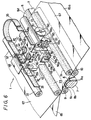
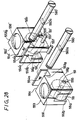
- a sheet c of a photo-sensitive material which is desirably in the form of a long web or film, and a sheet d of the developing paper are pressed together between a pair of vertically superposed cylindrical pressure rollers e and f having axial lengths somewhat greater than the width of the sheets c and d .
- the lower pressure roller e is rotatably mounted in a suitable support frame (not shown) and rotated by a motor (also not shown).
- the upper pressure roller is rotatably mounted in a vertically movable frame which is pressed downward by one or more strong resilient members (not shown) so that the roller f is pressed downwardly against the roller e .
- a frame or area of the web or sheet c of photo-sensitive material is exposed to a light image before being brought together with the sheet d of developing paper, whereupon the sheets c and d are fed together between the pressure rollers e and f .
- the upper roller f pressed thereagainst is also rotated so that the sheet c of photo-sensitive material and the sheet d of developing paper are moved together while being pressed between the rollers e and f .
- the apparatus a has the advantage of providing a relatively high printing speed since the sheets of the developing paper and the photo-sensitive material are pressed together while being continuously transported or advanced by the rotated rollers e and f .
- the rollers e and f act to press together the sheets c and d simultaneously along a stripe-like area extending across the entire width of the sheets. Therefore, in order to provide the requisite pressure at each increment of such stripe-like area to ensure rupture of those microcapsules that have not been fully hardened, and further to ensure transfer of the precursors of pigments from the ruptured microcapsules to the sheet of developing paper, a very large force must be provided to urge the roller f toward the roller e .
- the sheet c of photo-sensitive material and the sheet d of developing paper be pressed together with a pressure of 30 to 40 kg/mm2.
- the force urging together the rollers has to be about 57 kg for each cm of roller length, that is, a total force of about 1200 kg for rollers having lengths of 21 cm.
- the apparatus a in order to be capable of applying such a large force to urge together the rollers e and f , must be massive and requires a high-powered motor and a transmission mechanism to transmit the torque to the lower pressure roller e . As a result of the foregoing, the apparatus a is relatively expensive and difficult to assemble and maintain.
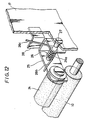
- apparatus b which, as shown in Figure 2, comprises a fixed back-up member g defining an upwardly facing back-up surface g ′, and a pressure member h having a spherical ball i rotatably mounted at its lower end.
- the sheets c and d of the photo-sensitive material and the developing paper, respectively, are brought into contact with each other and transported intermittently across the back-up surface g ′ in a direction of sheet travel that is transverse to the length of the back-up surface g ′.
- the pressing member h is mounted for reciprocal movements in the direction along the back-up surface g ′.
- the pressing member h is mounted for reciprocal movements in the direction along the back-up g ′, that is, perpendicular to the direction of sheet travel, between terminal positions h 1 and h 2, shown in dotted-lines in Figure 2, and at which the pressing member h is situated laterally beyond the side edges of the sheets c and d .
- the pressing member h is urged downwardly so that the ball i exerts pressure to urge together the sheets c and d against the back-up surface g ′ progressively along a narrow pressing region extending across the entire width of the contacting sheets c and d .
- the described pressing step is effected repetitively with intervening sheet transporting steps during each of which the sheets c and d are incrementally advanced.
- the apparatus b Since the ball i of the pressing member h acts, at any time, against only a very small area of the contacting sheets c and d , the requisite pressure to ensure the rupture of the unhardened microcapsules and the transfer of the released pigment precursors into adequate contact with the developing substances can be achieved with only a moderate force urging the pressing member h toward the back-up surface g ′.
- the apparatus b is disadvantageous in that its printing speed is low because developing of the picture is effected by alternating the movements of the pressing member h across the contacting sheets c and d and the intermittent transport of the sheets c and d of the photo-sensitive material and the developing paper.
- the contact pressure between the ball i of the pressing member h and the back-up surface g ′ is not uniform across the width w of the pressing area, as indicated by the pressure distribution curve j .
- the contact pressure between the ball i and the back-up surface g is highest at the centre of the ball and is reduced therefrom toward the opposite sides of the pressing area.
- the pressure urging together the sheet c of photo-sensitive material and the sheet d of developing paper d is highest at the centre of the pressing area and progressively reduces towards the opposite margins of such area. Therefore, for any particular degree of exposure, more of the microcapsules will be ruptured to release the respective pigment precursors along the center of the passing area than along the opposite side margins thereof.
- the concentration of development on the sheet d of developing paper is highest at the centre of each of the stripe-like pressing regions and is gradually reduced or diminished toward the opposite edges of each such pressing region or area, as indicated by the successive concentration distribution curves k in Figure 3B.
- the printed or developed picture will have a striped pattern resulting from the irregular concentration of development.
- the pressing member h will act on the sheets c and d along overlapping pressing areas with the result that the developed or printed picture will have a more uniform concentration of development on the sheet d of developing paper, as indicated by the concentration distribution curves k in Figure 3C.
- concentration distribution curves k in Figure 3C such reduction of the incremental movements of the sheets c and d will very substantially increase the printing or developing time and thereby considerably reduce the printing speed.
- the roller l has a cylindrical peripheral surface and is mounted for bodily movements relative to the back-up member g parallel to the back-up surface g ′ in directions perpendicular to the direction of intermittent sheet travel, and during such movements of the roller l , the roller l is urged toward the back-up surface g ′ with the sheets c and d of photo-sensitive material and developing paper being in contact with each other between the roller l and the back-up surface g ′ so as to be pressed together thereby.
- the cylindrical peripheral surface of the roller l the width of the strip-like pressing area along which the sheets c and d are pressed together sufficiently uniformly to develop the picture can be substantially increased. Therefore, the printing or developing speed can be increased relative to that of the apparatus b of Figure 2.
- the roller l is moved off the contacting sheets c and d to a standby position on the back-up surface g ′ at one side or the other of the sheets c and d as shown in Figure 5.
- the roller l is moved from its standby position on the back-up surface g ′ at one side of the path of travel of the sheets c and d laterally across the contacting sheets in a pressing step to a standby position onto back-up surface g ′ adjacent the opposite sides of the sheets c and d whereupon an incremental movement of the sheets c and d is effected in another sheet transporting step.
- the sheet pressing and transporting steps are alternately performed in a repetitive manner and, due to the relatively wide area along which the roller l can exert the requisite pressure against the contacted sheets c and d during each pressing step, a sufficiently high printing or developing speed can be realised.
- the contacting sheets c and d have a substantial thickness and, as shown in Figure 5, the opposite edges of the contacting sheets extend upwardly from the back-up surface g ′ at the standby positions of the roller l .
- apparatus to develop an image on a sheet of developing paper from a sheet of photo-sensitive material of a kind which develops the image upon the pressing together of the sheets of developing paper and photo- sensitive material
- the apparatus comprising: a back-up member having a back-up surface and standby surfaces extending from the opposite ends of the back-up surface and being raised relative to the backup surface to define guide shoulders at the ends of the back-up surface; means intermittently to transport the sheets of developing paper and photo-sensitive material in contact with each other across the back-up surface between the guide shoulders in a predetermined direction of sheet travel at a substantial angle to a longitudinal median of the back-up surface; at least one rotatable roller disposed in opposing relation to the back-up surface and having an axis of rotation substantially at right angles to the longitudinal median of the back-up surface; means to mount the roller for bodily movements relative to the back-up member toward and away from the back-up surface and parallel to the back-up surface in directions parallel to the longitudinal median thereof; means
- Such apparatus can be of relatively small size and low cost while reliably achieving developing of the picture at an acceptably high speed.
- a uniform developing concentration can be obtained and damage to the sheets of developing paper and photo-sensitive material and generation of objectionable noise during operation of the apparatus can be avoided.
- the sheets of developing paper and photo-sensitive material in contact with each other can be intermittently transported in a predetermined direction of sheet travel across the back-up surface and, during each interval when the sheets are at rest on the back-up surface, the rotatable roller can be transported along the back-up surface at a substantial angle to the direction of sheet travel while being urged toward the back-up surface to press together the sheets between the roller and back-up surface.
- the back-up surface can have raised guide shoulders at its opposite ends to guide the adjacent side edges of the sheets and thereby prevent relative shifting thereof during pressing together of the sheets or the intermittent transport thereof.
- Two contacting sheets for example, of developing paper and photo-sensitive material, respectively, which are of different hardness or rigidity, can be transported, in contact with each, across a curved back-up surface without being displaced relative to each other.
- the pressure exerted on the contacting sheets of developing paper and photo-sensitive material between a back-up surface and a roller transported there-across can be substantially uniformly distributed so as to achieve clear development of a picture without irregular concentrations of the development thereof.
- Self-alignment can be achieved with respect to the back-up surface and roller between which the contacting sheets of developing paper and photo-sensitive material are pressed together, thereby reducing the accuracy required in the assembly and adjustment of the respect parts.
- the force required to press together the sheets of developing paper and photo-sensitive material against the back-up surface can be minimized so as to make possible the provision of a relatively low cost apparatus that is compact and light in weight.
- the frictional resistance to the intermittent transportation of the sheets of developing paper and photo-sensitive material across the back-up surface can be minimized so as to avoid irregular movements of the sheets that would adversely affect uniform development.
- apparatus to develop an image on a sheet of developing paper from a sheet of photo-sensitive material which is more rigid than the sheet of developing paper and of a kind which develops the image upon pressing together of the sheets of the developing paper and the photo-sensitive material
- the apparatus comprising: means defining a back-up surface having a longitudinal median; means intermittently to transport the sheets of the developing paper and the photo-sensitive material in contact with each other across the back-up surface in a predetermined direction of sheet travel which is at a substantial angle to the longitudinal median thereof, and, with the sheet of photo-sensitive material contacting the back-up surface; at least one rotatable roller disposed in opposing relation to the back-up surface and having an axis of rotation substantially at right angles to the longitudinal median of the back-up surface; means to mount the roller for bodily movements toward and away from the back-up surface and parallel to the back-up surface in directions parallel to the longitudinal median thereof; and means to transport the roller relative to the back-up surface in the directions parallel to the longitudinal median
- apparatus to develop an image on a sheet of developing paper from a sheet of photo-sensitive material of a kind which develops the image upon the pressing together of the sheets of the developing paper and the photo-sensitive material
- the apparatus comprising: means defining a back-up surface having a longitudinal median; means intermittently to transport the sheets of the developing paper and the photo-sensitive material in contact with each other in a predetermined direction of sheet travel across the back-up surface; at least one rotatable roller disposed in opposing relation to the back-up surface and having an axis of rotation extending at right angles to the longitudinal median; means mounting the roller for bodily movements toward and away from the back-up surface and parallel to the back-up surface in directions parallel to the longitudinal median of the back-up surface; and means to transport the roller across the back-up surface in the directions parallel to the longitudinal median while urging the roller toward the back-up surface with the sheets of the developing paper and the photo-sensitive material being in contact with each other between the roller and the back-up surface so as
- the sheet of photo-sensitive material which is more rigid or harder than the sheet of developing paper can be arranged to contact the back-up surface while the roller which exerts the pressure rolls across the relatively soft sheet of developing paper in being transported from one to another of the standby surfaces.
- apparatus to develop an image on a sheet of developing paper from a sheet of photo-sensitive material of a kind which develops the image upon the pressing together of the sheets of the developing paper and the photo-sensitive material
- the apparatus comprising: means defining a back-up surface having a longitudinal median; means intermittently to transport the sheets of the developing paper and the photo-sensitive material in contact with each other in a predetermined direction of sheet travel across the back-up surface at a substantial angle to the longitudinal median; at least one rotatable roller disposed in opposing relation to the back-up surface and having an axis of rotation extending substantially at right angles to the longitudinal median; means to mount the roller for bodily movements toward and away from the back-up surface and parallel to the back-up surface in directions parallel to the longitudinal median thereof; means to transport the roller across the back-up surface in the directions parallel to the longitudinal median while urging the roller toward the back-up surface with the sheets of the developing paper and the photo-sensitive material in contact with each other between the roller and the back
- the back-up surface and the roller can be configured so that, during the transporting of the roller across the back-up surface from one to another of the standby surfaces, the contact pressure between the peripheral surface of the roller and the back-up surface is smaller at the opposite margins of such peripheral surface than at any other portion thereof latter between such margins.
- apparatus to develop an image on a sheet of developing paper from a sheet of photo-sensitive material of a kind which develops the image upon the pressing together of the sheets of the developing paper and the photo-sensitive material
- the apparatus comprising: a back-up cylinder defining a peripheral back-up surface with rounded edges at the opposite ends of the back-up surface; means intermittently to turn the cylinder and thereby transport the sheets of the developing paper and the photo-sensitive material in contact with each other in a predetermined direction of sheet travel across the back-up surface; at least one rotatable roller disposed in opposing relation to the back-up surface and having an axis of rotation extending parallel to the predetermined direction of sheet travel; means mounting the roller for bodily movements relative to the back-up cylinder toward and away from the back-up surface and parallel to the back-up surface in directions perpendicular to the predetermined direction of sheet travel between standby positions situated beyond the opposite ends of the back-up surface surface; means to transport the roller relative to the back
- At least one of the back-up surface and the peripheral surface of the roller can be formed with minute concave and convex surface irregularities distributed thereover so that the force urging the roller toward the back-up surface causes contact pressure to be applied to the sheets of developing paper and photo-sensitive material at the localized areas defined by the convex surface irregularities.
- the requisite, relatively high contact pressures can be achieved by only moderate forces urging the roller toward the back-up surface.
- apparatus to develop an image on a sheet of developing paper from a sheet of photo-sensitive material of a kind which develops the image upon the pressing together of the sheets of the developing paper and the photo-sensitive material
- the apparatus comprising;: means defining a back-up surface having a longitudinal median; means intermittently to transport the sheets of the developing paper and the photo-sensitive material in contact with each other in a predetermined direction of sheet travel across the back-up surface at a substantial angle to the longitudinal median; first and second rotatable rollers arranged in tandem in opposing relation to the back-up surface and each having an axis of rotation extending substantially at right angles to the longitudinal median; means to mount the rollers for bodily movements toward and away from the back-up surface and parallel to the back-up surface in directions parallel to the longitudinal median; and means operative when the sheets are at rest on the back-up surface to transport the rollers relative to the back-up surface in the directions parallel to the longitudinal median while urging the rollers toward the back-up surface so that
- First and second rotatable rollers can be assembled together in tandem so that such rollers successively press together the sheets of developing paper and photo-sensitive material between the rollers and the back-up surface across which the sheets of developing paper and photo-sensitive material are intermittently transported.
- apparatus to develop an image on a sheet of developing paper from a sheet of photo-sensitive material of a kind which develops the image upon the pressing together of the sheets of the developing paper and the photo-sensitive material
- the apparatus comprising: a back-up member have a back-up surface with a longitudinal median; means intermittently to transport the sheets of the developing paper and the photo-sensitive material in contact with each other across the back-up surface in a predetermined direction of sheet travel at a substantial angle to the longitudinal median; at least one rotatable roller disposed in opposing relation to the back-up surface and having an axis of rotation extending substantially at right angles to the longitudinal median of the back-up surface; means to mount the roller for bodily movements relative to the back-up member toward and away from the back-up surface and parallel to the back-up surface in directions parallel to the longitudinal median; means to transport the roller relative to the back-up surface in the directions parallel to the longitudinal median while urging the roller toward the back-up surface with the sheets of the developing
- Either the back-up member defining the back-up surface or the roller or assembly of rollers can be provided with a self-aligning mounting automatically to attain a desired attitude of the peripheral surface of each roller relative to the back-up surface.
- apparatus to develop an image on a sheet of developing paper from a sheet of photo-sensitive material of a kind which develops the image upon pressing together the sheets of developing paper and photo-sensitive material
- the apparatus comprising: means defining an upwardly facing back-up surface having opposed parallel margins extending longitudinally therealong, the back-up surface being convex and having a rectilinear generatrix extending parallel with the margins; means intermittently to transport the sheets of developing paper and photo-sensitive material in contact across the back-up surface in a direction of sheet travel at a substantial angle to the longitudinal margins of the back-up surface and including sheet guide means disposed before and after the back-up surface considered with respect to the direction of sheet travel, the sheet guide means defining paths for the sheets extending to and from the back-up surface and which converge and diverge, respectively, with respect to a plane tangential to the back-up surface at the top of the back-up surface, the paths being disposed between the plane and the back-up
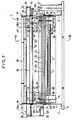
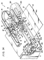
- a developing apparatus or printer 1 generally comprises a lower frame structure 2 formed of a base plate 3 of substantially rectangular shape and side walls 4 and 4′ extending upwardly from the opposite side portions of the base plate 3.
- a cylindrical bar 5 extends horizontally between and connects front end portions of the side walls 4 and 4′ at a vertical position that is approximately 2/3 the distance from the base plate 3 to the upper edges of the side walls 4 and 4′, and a rear wall 6 of the frame structure 2 extends between and connects the rear end portions of the side walls 4 and 4′ (Fig. 9).
- An elongate back-up member 7 of a relatively hard metal extends laterally between, and is suitably fixed at its end to the side walls 4 and 4′ of the frame structure 2.
- the back-up member 7 is shown to be located at a level near the top of the lower frame structure 2 and is positioned intermediate the front and back thereof.
- the back-up member 7 desirably has a vertically elongate cross-section so as to form a beam that is strongly resistant to flexing under loads applied from above.
- Such vertically elongate cross-section may be substantially elliptical or, as shown in Figs. 6 and 9, at least an upper surface 8 of the back-up member 7 is upwardly convex and has a rectilinear generatrix extending parallel to the longitudinal axis of the back-up member 7. More specifically, the upper surface 8 may be defined by a circular arcuate portion of the cross-section of the member 7 which is highest at the longitudinal median 8 d (Fig. 6) of the back-up member 7 and which, may, for example, have a radius of curvature of about 10mm.
- the upper surface 8 of the back-up member 7 is divided to provide a back-up surface 8 a having a length, measured in the lateral direction of the apparatus 1, corresponding to the width of the sheets of developing paper and photo-sensitive material to be employed in the apparatus, and standby surfaces 8 b extending from the opposite ends of the back-up surface 8 a and raised relative to the surface 8 a to define guide shoulders 8 c at the ends of the back-up surface 8 a , as particularly shown in Fig. 14.
- the height of the guide shoulders 8 c at the opposite ends of the back-up surface 8 a is preferably selected to be approximately equal to the combined thickness of the developing paper and photo-sensitive material to be pressed together against the back-up surface 8 a .
- a drive or feed roller 9 extends parallel to and behind the back-up member 7 with a relatively small spacing therebetween and with the top of the feed roller 9 being located below the upper surface 8 of the back-up member 7.
- a tension roller 10 is similarly disposed in front of the back-up member 7, and the feed and tension rollers 9 and 10 are rotatably supported at their respective ends by the side walls 4 and 4′.
- the rollers 9 and 10 are driven to rotate at predetermined times, as hereinafter described in detail, in the clockwise direction, as viewed in Fig. 9, by means of a sheet transporting motor 11 mounted on the base plate 2 and connected with the rollers 9 and 10 through suitable speed reduction mechanisms 12 and 12 (Figs. 8 and 9).
- the feed roller 9 is rotated at a slightly slower speed than the tension roller 10 so that the sheets of developing paper and photo-sensitive film or material being transported by the rollers 9 and 10 are slightly tensioned therebetween.
- a locking member 14 extends between the side walls 4 and 4′ at the front of the lower frame structure 2 and has end flanges pivotably supported on the cylindrical bar 5 and terminating at their upper ends, in locking claws 14 a for a purpose described below.
- a light source 15 which is desirably formed of a bundle of numerous optical fibres and hereinafter referred to as an FOT (Fig. 9), is suitably mounted within the lower frame structure 2 behind and below the back-up member 7 and has a light-emitting surface 15 a facing rearwardly for use to expose a sheet or frame of photo-sensitive film or material as hereinafter described in detail.
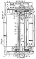
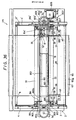
- the apparatus 1 is further shown to comprise a movable upper frame structure 16 (Figs. 7-9) composed of opposite side walls 17 and 17′ space apart laterally by substantially the same distance as the side walls 4 and 4′ of the lower frame structure 2, and cross members 18 and 19 which extend between, and connect upper portions of the side walls 17 and 17′.
- the side walls 17 and 17′ are rotatably mounted, at their lower rear ends, on pivots 20 extending from the side walls 4 and 4′ at the upper rear ends thereof.
- the upper frame structure 16 is pivotably movable between the horizontal operative position shown in full lines in Fig. 9 and the upwardly pivoted open position indicated in dotted lines at 16′ on Fig. 9.
- Locking pins 21 extend inwardly from the side walls 17 and 17′ adjacent the lower front portions thereof (Fig. 9) and are engaged by the locking claws 14 a of the locking member 14 to secure the upper frame structure 16 in its opposite horizontal position.
- Cylindrical guide shafts 22 extend parallel to each other laterally across the upper frame structure 16 and are suitably mounted, at their opposite ends, on the side walls 17 and 17′.
- the guide shafts 22 are spaced apart and located so that, in the operative position of the movable upper frame structure 16, the guide shafts 22 will be disposed equal distances in front and to the rear of a vertical plane extending through the longitudinal median of the back-up member 7.
- the upper frame structure 16 also has mounted therein two follow-up or sheet-guiding rollers 23 and 24 which are mounted, as hereinafter described in detail, so as to press downwardly from above on the feed roller 9 and the tensioning roller 10, respectively, when the frame structure 16 is in its operative position. As shown particularly in Figs.
- rollers 23 and 24 are rotatably carried by free end portions of respective support arms 25 which are, in turn, pivoted on support pins 27 extending from the adjacent side walls 17 and 17′.
- a torsion spring 26 is associated with each of the support arms 25 and includes a coil portion 26 a mounted on the respective pin 27 and spring arms 26 b and 26 c which respectively bear against the associated support arm 25 and a spring abutment 28 extending from the adjacent side wall 17 or 17′.
- Each torsion spring 26 is effective angularly to urge the respective support arm 25 in the direction to move the mounted roller 23 or 24 downwardly toward the underlying roller 9 or 10, respectively.
- a reversible motor 29 is supported, with its shaft 29 a extending vertically upward, in a mounting bracket 30 directed outwardly from the side wall 17 of the movable frame structure 16.
- a drive pulley 31 is secured to the upper end of the motor shaft 29 a and, as shown on Fig. 8, is positioned approximately midway between the axes of the guide shafts 22, but at a slightly higher level.
- a driven pulley 32 is rotatably mounted on a shaft 34 which is carried by a support bracket 33 extending outwardly from the side wall 17′ and which is substantially in lateral alignment with the motor shaft 29 a .
- An endless drive belt 35 extends around the pulleys 31 and 32 to transport a carriage and roller assembly 41 along the guide shafts 22, that is, in directions parallel to the longitudinal axis of the back-up member 7, as hereinafter described in detail.
- Sensors 36 and 37 are mounted on the cross member 18 of the movable frame structure 16 adjacent the side walls 17 and 17′, respectively, to detect when the carriage and roller assembly 41 has attained the opposite extreme end positions within its range of travel between the side walls 17 and 17′.
- Each of the sensors 36 and 37 has a light-emitting element 38 and a light receiving element 39 positioned opposite each other and carried by a support member 40 suitably secured to a respective end portion of the cross member 18.
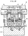
- the carriage and roller assembly 41 is shown in Figs. 10 and 11 to include a carriage 42 comprising a generally block-shaped body 43 having parallel, spaced apart flanges 45 depending from the bottom of the body 43, and a pair of through-bores 44 extending vertically through the mid-portion of the body 43 between the flanges 45 and arranged in tandem parallel to the direction in which the flanges 45 extend.
- the spaced apart flanges 45 have aligned holes 46 extending therethrough at locations midway along the lengths of the flanges 45.
- a through hole 47 is bored through the body 43 in the direction at right angles to the holes 46 and at a location diametrically to intersect the bores 44 at locations approximately midway between the open upper and lower levels of the bores 44.
- cover members 48 and 48′ extend forwardly and rearwardly from the top of the body 43 of the carriage 42 and are dimensioned to extend over the guide shafts 22 when the body 43 is situated between the shafts 22. Projections 49 depend from the cover members 48 and 48′ so as to be positioned above the guide shafts 22 with a small clearance therebetween when the carriage and roller assembly 41 is mounted within the frame structure 16.
- the cover member 48 extending forwardly from the carriage body 43 has an integral flange 48 a directed upwardly therefrom to form a light shield which cooperates with the sensors 36 and 37, as hereinafter described.
- pairs of parallel spaced apart axles 50 extend forwardly and rearwardly, respectively, from the carriage body 43, and guide rollers 51 are rotatably mounted on such axles 50 and have relatively deep, V-shaped peripheral grooves 51 a which engage, from below, the guide shafts 22 disposed in front and at the rear of the carriage body 43.
- the carriage 42 is free to move laterally, that is, in directions parallel to the longitudinal axis of the back-up member 7 with the guide rollers 51 being engageable, from below, with the guide shafts 22, and with the projections 49 of the cover members 48 and 48′ opposing the upper surfaces of the guide shafts 22 with a small clearance therebetween.
- a connecting member 52 is secured to the top surface of the carriage body 43 and is connected to a run of the belt 35 between the pulleys 31 and 32 so that the carriage 42 is moved laterally in one direction or the other in response to operation of the motor 29 to rotate its shaft 29 a in either a forward or a reverse direction.
- the carriage and roller assembly 41 further includes roller support arms 53 and 54 having block-shaped major portions 53 a and 54 a , respectively.
- These major portions 53 a and 54 a of the roller support arms are formed with respective downwardly opening central cutouts so as to divide the lower parts of the major portions 53 a and 54 a into bifurcated depending parts 53 b and 54 b , respectively, which are formed with aligned holes 55 extending therethrough.
- the top surfaces of the block-shaped major portions 53 a and 54 a are formed with shallow circular recesses 56.
- the major portions 53 a and 54 a of the roller support arms 53 and 54 respectively, have oppositely offset, integral projections 57 extending therefrom and formed with through holes 57 a parallel with the holes 55.
- Each of the projections 57 has a semi-cylindrical end surface portion 57 b which is coaxial with the respective through hole 57 a .
- the support arms 53 and 54 are dimensioned so that the major portions 53 a and 54 a thereof can fit between the depending flanges 45 of the carriage 42 with the projections 57 of the support arms 53 and 54 being arranged side-by-side and having their through holes 57 a axially aligned with each other and with the holes 46 in the flanges 45.
- a single shaft 60 extends through the holes 46 in the flanges 45 and through the holes 57 a in the projections 57 of the support arms 53 and 54 so as pivotally to mount the support arms 53 and 54 to rock about the axis of the support shaft 60.
- Pressing rollers 58 and 58′ of disc shape are provided with a thickness or axial dimension about 1/4 the width of the back-up surface 8 a , for example, a width of about 4mm, and are made of a metal of substantially high hardness.
- the outer peripheries 58 a and 58′ a of the pressing rollers 58 and 58′ are cylindrical, that is, each of the peripheral surfaces 58 a and 58′ a has a rectilinear generatrix extending parallel to the axis of the respective roller.
- the pressing rollers 58 and 58′ are further formed with central, axially extending bores 58 b and 58′ b which rotatably receive respective axles 59 and 59′.
- the axles 59 and 59′ are press fitted in the holes 55 and extended loosely through the bores 58 b and 58′ b of the pressing rollers 58 and 58′.
- the pressing rollers 58 and 58′ are rotatably supported by the arms 53 and 54 with the axes of rotation of the rollers 58 and 58′ being spaced apart at opposite sides of the pivoting axis defined by the shaft 60, and with the resulting tandem-arranged rollers 58 and 58′ having their lower portions projecting downwardly from the support arms 53 and 54 for rolling engagement with sheets backed-up by the surface 8 a of the back-up member 7, as hereinafter described.
- Substantially cylindrical spring bearings 61 and 61′ are provided, near their upper ends, with flanges 61 a , and are loosely received in the holes 44 through the open upper ends thereof.
- the spring bearings 61 and 61′ are further formed with diametrically extending bores 61 b extending therethrough below the flanges 61a.
- Helical compression springs 63 and 63′ are arranged around the spring bearings 61 and 61′, respectively, and bear at their upper ends against the flanges 61 a on the respective spring bearings 61 and 61′, while the lower ends of the springs 63 and 63′ seat in the circular recesses 56 in the top surfaces of the roller support arms 53 and 54, respectively.
- a single support pin 62 passes through the diametrical bores 61 b in the spring bearings 61 and 61′ and is press fitted in the holes 47 provided in the body 43 of the carriage 42, thereby fixedly positioning the spring bearings 61 and 61′ within the respective holes 44.
- Such positioning of the spring bearings 61 and 61′ is effective to compress the springs 63 and 63′ so that they urge the roller support arms 53 and 54 to rock downwardly about the shaft 60, and thereby urge the pressing rollers 58 and 58′ downwardly against the upper surface 8 on the back-up member 7.
- the main portions 53 a and 54 a of the roller support arms 53 and 54 desirably are provided with stop members (not shown) projecting from their confronting surfaces for limiting downward swinging movements of the support arms 53 and 54 when such movements are not limited by engagement of the rollers 58 and 58′ with the back-up member 7.
- stop members projecting from their confronting surfaces for limiting downward swinging movements of the support arms 53 and 54 when such movements are not limited by engagement of the rollers 58 and 58′ with the back-up member 7.
- the stop member extending from each of the support arms 53 and 54 is engageable with the confronting surface of the other of such support arms to limit the swinging movements of the arms 53 and 54 by the springs 63 and 63′, and thereby prevent inadvertent downward ejection of the springs 63 and 63′ from the respective holes 44.
- the pressing rollers 58 and 58′ are pressed downwardly by the springs 63 and 63′ against the upper surface 8 of the back-up member 7 and, in reaction thereto, the carriage 42 is urged upwardly so that the guide rollers 51 are pressed against the lower sides of the guide shafts 22.
- the pressing rollers 58 and 58′ roll in tandem, that is, one after the other, along the upper surface 8 of the back-up roller 7 with the longitudinal median 8 d (Fig. 6) of the upper surface 8 of the back-up member being centred with respect to the width of the peripheral surfaces 58 a and 58′ a of the pressing rollers and at right angles to the axes of rollers 58 and 58′.
- the carriage and roller assembly 41 When the carriage and roller assembly 41 reaches a position at one end of its movable range, that is, a position adjacent the side wall 17 of the upper frame structure 16, the light shield 48 extending from the carriage 42 is interposed between the light-emitting element 38 and the light-receiving element 39 of the sensor 36 and the resulting interruption of the reception of light by the element 39 is detected as an indication of the arrival of the carriage and roller assembly 41 at that one end position.
- the light shield 48 is then interposed between the light-emitting element 38 and the light-receiving element 39 of the sensor 37 and the resulting interruption in the reception of light by the element 39 and the sensor 37 is detected as an indication that the carriage and roller assembly 41 has attained its other end position.
- the sheet of photo-sensitive material is shown to be in the form of a long photo-sensitive film 65 which is unwound from a reel within a film cassette 64 (Fig. 9) suitably disposed within the lower rear portion of the lower frame structure 2 with the axis of its reel extending laterally and with a film outlet 64 a of the cassette directed upwardly.
- a film cassette 64 (Fig. 9) suitably disposed within the lower rear portion of the lower frame structure 2 with the axis of its reel extending laterally and with a film outlet 64 a of the cassette directed upwardly.
- the photo-sensitive film 64 drawn out of the outlet 64 a of the cassette 64 is directly upwardly past the light-emitting surface 15 a of the FOT 15 and then around a film guide roller 66 and forwardly therefrom so as to pass in succession between the drive or feed roller 9 and the sheet-guiding roller 24 prior to being directed downwardly as shown at 65′ and rewound on a take-up reel or spool (now shown).
- the photo-sensitive film 65 may be formed of an appropriate transparent film base with one side, indicated at 65 a on Fig. 9 and hereinafter referred to as the exposure side, being coated with an almost infinite number of microcapsules or particles of a suitable resin which contain respective pigment precursors and which are optically hardened when exposed to light images of corresponding wavelengths.
- the hardened microcapsules are substantially indestructible even when subjected to substantial pressures, but those microcapsules which have not been hardened can be crushed or ruptured by pressure to release the corresponding colour precursors which can then chemically react with developing substances or agents to provide the corresponding colours of pigments.
- the developing substances or agents are coated on one side 67 a , hereinafter referred to as the developing side, of sheets 67 of developing paper on which colour pictures or images are to be printed.
- the photo-sensitive film 65 has its exposure side 65 a facing upwardly as the film travels forwardly from the guide roller 66 and into the nip between the feed roller 9 and sheet guiding roller 23.
- the sheets 67 of developing paper which are rectangular and may have a width slightly large than that of the photo-sensitive film 65, are stacked in a paper supply tray or magazine 68 with the developing sides 67 a of the sheets 67 facing downwardly.
- the paper supply tray 68 is suitably mounted within the upper frame structure 16 above the pivoting axis thereof defined by the pivots 20 and, in the operative position of the upper frame structure 16, the paper supply tray 68 is inclined downwardly in the forward direction.
- a paper supply roller 69 is suitably mounted above the forward end portion of the paper supply tray 68 and a resilent bottom member of sheet lifter 68 a is provided within the tray 68 below the stack of sheets 67 therein to urge the stack upwardly and thereby cause frictional engagement of the topmost sheet 67 in the stack with the paper supply roller 69.
- each supplied sheet 67 has its downwardly facing developing side 67 a contacted by the upwardly facing exposure side 65 a of the film 65 and is fed therewith between the feed or drive roller 9 and the sheet guiding roller 23 and onto the back-up surface 8 a of the back-up member 7.
- the film 65 and a sheet 67 of the developing paper are fed together betwen the tensioning roller 10 and the respective sheet guiding roller 24 whereupon the film 65 is diverted downwardly, for example, as indicated schematically at 65′ while the sheet 67 having the developed or printed colour image or picture thereon is suitably stripped from the film and passed out of the apparatus 1 along a paper discharge guide plate 70 at the front of the apparatus.
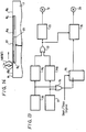
- a circuit for controlling the operations of the motor 11 intermittently to transport the photo-sensitive film 65 and the successive sheets 67 of developing paper and of the motor 29 for effecting movements of the carriage and roller assembly 41 laterally along the back-up member 7 generally comprises monostable multi-vibrators 71L and 71R which are triggered in response to the reception of detection signals from the sensors 36 and 37, respectively.
- the monostable multi-vibrators 71L and 71R are selectively operated to produce pulses of a predetermined pulse width in response to signals of logic level [1] from the sensors 36 and 37, respectively.
- Such signal of logic level [1] is obtained from the sensor 36 or 37 when it detects the arrival of the carriage and roller assembly 41 at the respective one of its end positions at which the rollers 58 and 58′ are situated on the respective one of the stand-by surfaces 8 b of the back-up member 7, and thus are removed from the sheet 67 and the film 65 carried by the back-up surface 8 a .
- the pulse of a predetermined pulse width from the monostable multi-vibrator 71L or 71R is transmitted through and OR circuit 72 to a motor drive circuit 73 for the motor 11.
- the sheet transporting motor 11 is operated for a period of time determined by the width of a pulse from the monostable multi-vibrator 71L or 71R and, during such period of time, the motor 11 causes transport of the photo-sensitive film 65 and the developing paper sheet 67 through a predetermined increment of movement.
- each of the sensors 36 and 37 produces a signal of logic level [1] for triggering the respective monostable multi-vibrator 71L or 71R when the light shield 48 a on the carriage 42 is interposed between the light-emitting and light-receiving elements 38 and 39 of the respective sensor 36 or 37, that is, when the carriage and roller assembly 41 reaches the respective end position in its range of movements.
- the sensors 36 and 37 output a signal of logic level [0] whenever the light shield 48 a is removed from between the light-emitting and light-receiving elements 38 and 39 of the respective sensor.
- the control circuit of Fig. 13 is further shown to include an OR circuit 74 which is supplied with the outputs from the sensors 36 and 37 and has its output connected to the input of a flip-flop circuit 75 which has its output supplied to a motor drive circuit 76 for the motor 29 by which the carriage and roller assembly 41 is moved laterally across the film 65 and sheet 67 on the back-up surface 8 a from one to the other of the opposite end positions of the assembly 41.
- the flip- flop circuit 75 provides an output which is alternatively positive or negative polarity for causing forward or reverse operation, respectively, of the motor 29 in response to successive outputs from the OR circuit 74.
- the flip-flop circuit 75 in response to each output of logic level [1] from the OR circuit 74, the polarity of the output from the flip-flop circuit 75 is changed.
- the flip-flop circuit 75 is also shown to be supplied with a start/stop signal.
- a start signal is supplied to the flip-flop circuit 75 when the apparatus 1 is to perform a printing or developing operation and, in response to such start signal, the flip-flop circuit 75 provides an output to the motor drive circuit 76 with the polarity of such output being reversed in response to successive outputs from the OR circuit 74.
- the flip-flop circuit 75 when the flip-flop circuit 75 received a stop signal to halt the printing or developing operation by the apparatus 1, the flip-flop circuit 75 provides no output to the motor drive circuit 76 with the result that the motor 29 is maintained in an inoperative condition.
- Fig. 13 further shows that the output of the OR circuit 72 is also supplied to the motor drive circuit 76 as a disabling signal therefore.
- the motor drive circuit 76 is inhibited from operating the motor 29 so that the carriage and roller assembly 41 will remain in one or the other of its end positions with the rollers 58 and 58′ resting on one of the stand-by surfaces 8 b during each incremental movement or transport of the film 65 and sheet 67.
- the carriage and roller assembly 41 is disposed at one or the other of its end positions and waits at such end position with its rollers 58 and 58′ resting on the respective one of the stand-by surfaces 8 b , while the photo-sensitive film 65 is intermittently transported by the drive roller 9 and associated guiding roller 23 and by the tension roller 10 and associated guiding roller 24.
- the exposure side 65 a of the film 65 is exposed line-by-line to light passing through the transport base of the film so as to provide an exposure of the desired picture on a prescribed area or frame of the film 65 constituting a frame thereof.
- a sheet 67 of developing paper is supplied from the tray 68 so as to overlap the exposed frame of the film 65 between the rollers 9 and 23 and onto the back-up surface 8 a of the back-up member 7.
- the arrival of the leading end of the exposed frame of the photo-sensitive film 65 at the top or longitudinal median 8 d of the back-up surface 8 a is detected by a suitable sensor (not shown) to provide a start signal by which the flip-flop circuit 75 causes the motor drive circuit 76 to effect operation of the motor 29 in the direction to move the carriage and roller assembly 41 away from the end position at which it resides while awaiting the arrival of the exposed frame of the film.
- the pressing rollers 58 and 58′ In response to such operation of the motor 29, the pressing rollers 58 and 58′, while pressing together the sheet 67 of developing paper and the photo-sensitive film 65 against the back-up surface 8 a of the member 7, roll in one or the other lateral direction, that is, a direction perpendicular or at least at a substantial angle to the direction of feeding movement or transport of the film 65 and sheet 67, so that the rollers 58 and 58′ scan across the sheet 67 of developing paper and the photo-sensitive film 65 in the direction of the width thereof.
- a stripe band-shaped area extending across the width of the sheet 67 of developing paper and the photo-sensitive film 65 is subjected to pressure between the pressing rollers 58 and 58′ and the back-up surface 8 a to cause developing of the corresponding band-shaped area of the exposed colour picture on the sheet 67.
- the sensor 36 or 37 detects the arrival of the assembly 41 at such other end position and provides a signal of logic level [1] through the OR circuit 74 to the flip-flop 75 to invert the polarity of the output from the flip-flop circuit.
- the signal of logic level [1] from the sensor 36 or 37 triggers the respective monostable multi-vibrator 71L or 71R, and the resulting output pulse from the triggered monostable multi-vibrator is passed through the OR circuit 72 to the motor drive circuit 76 to inhibit any operation of the motor 29 for the duration of such pulse.
- the carriage and roller assembly 41 remains at rest at one or other of its end positions, while the motor drive circuit 73 responds to such pulse to cause operation of the motor 11 by which a further increment of movement of the sheet 67 together with the film 65 is effected.
- the absence of any pulse fed from the OR circuit 72 to the motor drive circuit 76 enables the circuit 76 to effect renewed operation of the motor 29 in the direction corresponding to the polarity of the out put then being received by the motor drive circuit 76 from the flip-flop circuit 75.
- the carriage and roller assembly 41 is moved laterally or returns to its original end position and, during such movement, the rollers 58 and 58′ press together the sheet 67 of developing paper and the photo-sensitive film 65 against the back-up surface 8 a in another band-shaped pressing area that abuts or partially overlaps the band shaped area in which the sheet 67 and film 65 were previously pressed together.
- the pressing rollers 58 and 58′ press together a band-shaped area of the photo-sensitive film 65 and the sheet 67 of developing paper against the back-up surface 8 a by rolling thereacross in the direction of the width of the film 65, the area at which each of the rollers 58 and 58′ contacts the sheet 67 at any one time is very small so that the force exerted by each of the springs 63 and 63′ may be as small as 2 to 3 kg, as compared with the force of 1,000 to 1,500 kg required to press together the rollers e and f in the previously proposed arrangement of Fig. 1.
- the pressing rollers 58 and 58′ can roll relatively smoothly between the stand-by surfaces 8 b and the surface of the sheet 67 of developing paper to avoid damage to the side edges of the superposed film 65 and sheet 67, and also to avoid the generation of objectionable noise when moving on and off the opposite side edges of the sheet 67 and the film 65.
- each of the two rollers 58 and 58′ can be reduced without sacrificing the uniformity of the development concentration, damage to the photo-sensitive film 65 and the sheet 67 of developing paper, such as, tearing and wrinkling thereof, can be substantially prevented.
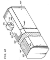
- FIG. 15 another embodiment of developing apparatus 1A is similar to the apparatus 1 previously described, but the back-up member 7 which defines the fixed back-up surface 8 a is replaced by a cylindrical back-up member 77 including a rotatable, cylindrical body portion 78 mounted on a shaft 79 and having an axial length substantially corresponding to the width of the sheet 67 of developing paper and the photo-sensitive film 65.
- Fixed opposite end portions 80 each have a diameter slightly larger than the diameter of the rotatable cylindrical body portion 78 so that the fixed end portions 80 define stand-by surfaces 80 b at their peripheries and guide surfaces or shoulders 80 c at the opposite ends of a back-up surface 80 a .
- the apparatus 1A operates similarly to the previously described operation of the apparatus 1 with the exception that, during the rolling movements of the roller 58 or of rollers 58 and 58′ laterally across the superposed sheet 67 and film 65 against the back-up surface 80 a from one to the other of the stand-by surfaces 80 b , the cylindrical body portion 78, which defines the back-up surface 80 a , is desirably held against rotation by a suitable locking means (not shown).
- a suitable locking means not shown.
- the cylindrical body portion 78 is similarly angularly displaced or turned while the roller 58 or rollers 58 and 58′ are disposed on one or the other of the fixed stand-by surfaces 80 b .
- the back-up surface 80 a does not give rise to any frictional resistance to such movements of the web 65 and sheet 67.
- relative displacements or shifting of the film 65 and sheet 67 are avoided to ensure clean development of the desired picture.
- the difference between the diameter of the rotatable cylindrical body-portion 78 and the diameter of the fixed end members 80 is selected so that the guide shoulders 80 c preferably have a radial dimension approximately equal to the combined thicknesses of the film 65 and sheet 67.
- the apparatus 1A has the previously described advantages of avoiding damages to the edges of the film 65 and sheet 67, and also of avoiding the generation of noise when the roller 58 or rollers 58 and 58′ are exposed to light and then pressed again the sheet of developing paper containing the developing agents or substances for providing the desired image or picture on the sheet of developing paper, it will be appreciated that the invention can be applied to other image forming systems which are responsive to the application of pressure.
- the invention may be similarly applied to a developing apparatus which employs a developing paper having both the photo-sensitive pigment precursors and the developing agents provided thereon and which is pressed against a sheet of copy paper on which the image is to be produced.
- the invention may be applied to a developing apparatus of the kind in which a photo-sensitive toner is used for printing and is pressed against and fixed on a copy paper by means of the apparatus embodying this invention.
- the developing apparatus in accordance with this invention may be applied to any arrangement in which a photo-sensitive material and a developing paper are moved together in face-to-face contact with each other and pressed against a back-up surface to provide the desired image or picture.
- the peripheral surface 58 a or 58′ a of the pressing roller 58 or 58′ is cylindrical and has a rectilinear generatrix extending parallel to the axis of rotation of the respective pressing roller, while the back-up surface 8 a or 80 a is outwardly or upwardly convex and has a rectilinear generatrix extending parallel to the longitudinal median of the back-up surface, that is, parallel to the directions in which the rollers 58 and 58′ are transported with the carriage 42 in the direction along the guide shafts 22.
- each of the rollers 58 and 58′ are shaped to diverge relative to each other from the median of the peripheral surface 58 a or 58′ a toward the opposite margins of such peripheral surface.
- each of the rollers 58 and 58′ exerts a pressure on the superposed sheet 67 and film 65 against the underlying back-up surface 8 a or 80 a which is substantially concentrated near the median of the peripheral surface of the pressing roller.
- each of such pressing rollers may be given the configuration of the roller 158 shown in Figs. 17 and 18.
- Each pressing roller 158 has a peripheral surface 158 a which is outwardly concave between its margins.
- Such outwardly concave peripheral surface 158 a has a radius of curvature R1 which is slightly larger than the radius of curvature R2 of the upwardly convex back-up surface 8 a of the back-up member 7.
- the radius of curvature R1 may be 15mm, while the radius of curvature R2 is 10mm.
- the surfaces 158 a and 8 a still diverge slightly from the longitudinal median of the back-up surface 8 a so that the contact pressure is larger at the median of the peripheral surface 158 a than at the margins thereof.
- the pressure distribution curve m1 tends more nearly to equalize the distribution of pressure across the width w of the peripheral surface of the roller 158 than would be the case for the previously described rollers 58 and 58′ when used with the back-up member 7.
- the apparatus 1B shown in Fig. 18 and employing the roller 158 in association with the back-up member 7 may be otherwise the same as the apparatus 1 or 1A previously described herein, so that only the details of the characteristic pressing roller 158 have been illustrated and described.
- Figs. 19 and 20 and Figs. 21 and 22 illustrate other cooperative arrangements of the pressing roller and the back-up surface by which the pressure distribution across the width of the pressing roller can be desirably influenced.
- each pressing roller 258 has a peripheral surface 258 a which is outwardly convex between the margins of the peripheral surface and is associated with a back-up member 107 having a flat back-up surface 108 a extending along the top thereof.
- the pressure distribution exerted by the roller 258 on a superposed sheet of developing paper and a photo-sensitive film against the flat back-up surface 108 a can be made substantially uniform across the width w of the pressing roller, but with the exerted pressure decreasing gradually near to the opposite margins of the peripheral surface 258 a , as indicated by the pressure distribution curve m 2 on Fig. 19.
- each pressing roller 358 has a cylindrical peripheral surface 358 a with a rectilinear generatrix extending parallel to the axis of rotation of the roller 358.
- the opposed flanks 358 b of the roller 358 are formed with annular recesses 358 c which are concentric with the axis of rotation of the roller.
- Such annular recesses 358 c are shaped so that the rim 358 d of the roller 358 tapers in thickness from the centre toward its opposite sides so that the rim 358 d has less rigidity at the opposite margins of the peripheral surface intermediate such margins. Therefore, when the roller 358 of the apparatus 1D presses a superposed sheet of developing paper and photo-sensitive film against the flat back-up surface 108 a , the pressure distribution across the width w of the pressing roller is substantially as indicated at m3 in Fig. 21, that is, there is obtained a substantially uniform pressure distribution with some diminishing of the pressure near the opposite margins of the peripheral surface of the roller. The foregoing may be distinguished from the pressure distribution indicated at m in Fig.
- All of the heretofore described embodiments of the invention employ a back-up surface and a pressing roller or rollers which are shaped relative to each other so that, during transport of each roller across the back-up surface from one to another of the stand-by surfaces, the contact pressure between the peripheral surface of each roller and the back-up surface is smaller at the opposite margins of the peripheral surface between such margins.
- Such pressure distribution is achieved by shaping at least one of the back-up surface and the peripheral surface of the or each pressing roller so as to diverge relative to the other of such surfaces from them median of the peripheral surface toward the opposite margins thereof, for example, as in the embodiments of Figs. 6-14, Figs, 15 and 16, Figs. 17 and 18, and Figs. 19 and 20, or by providing each pressing roller with a rim having less rigidity at the margins of the peripheral surface than at the median thereof, as in the embodiment of Figs. 21 and 22.
- the stripe or band-shaped area along which the sheet 67 and film 65 are pressed together against the back-up surface by each pressing roller rolling thereacross is made relatively wide, as compared with the narrow area of contact provided by the ball i of the pressing member h in the previously proposed arrangement of Fig. 3A, so that the increments of the intermittent transportation of the sheet 67 and the film 65 can be relatively increased corresponding to increase the developing or printing speed, without the danger that the contacting pressures under the margins of the peripheral surface of the pressing roller will be abnormally increased with resulting damage to the sheet of developing paper and/or to the photo-sensitive film.
- the embodiment shown in Figs. 17 and 18 has the further advantage that the combination of the pressing roller 158 having an outwardly concave peripheral surface 158 a with the upwardly convex back-up surface 8 a tends to stabilise the pressing roller 158 during its movement along the back-up surface 8 a with the result that relative shifting of the sheet of developing paper and the photo-sensitive film is avoided.
- each pressing roller has a cylindrical peripheral surface 58 a or 58′ a with a rectilinear generatrix parallel to its axis of rotation and is associated with a back-up surface 8 a on the member 7 which is upwardly convex and has a rectilinear generatrix extending parallel to the directions in which the roller 58 is transported
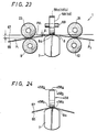
- the feed roller 9 in association with the tape guiding roller 23 and the tensioning roller 10 in association with the tape guiding roller 24 constitute guide means disposed before and after, respectively, the back-up surface 8 a considered with respect to the direction of travel of the sheet 67 of developing paper and the photo-sensitive film 65 across the back-up surface.
- the rollers 9 and 23 and the rollers 10 and 24 guide the superposed sheet 67 and the film 65 along paths P1 and P2 extending to and from, respectively, the back-up surface 8 a and which converge and diverge, respectively, with respect to the plane P l 1.
- the distance L is selected so that the paths P1 and P2 are disposed between the plane P l 1 and the back-up surface 8 a and are spaced from the surface 8 a at the opposed margins of the back-up surface.
- the optimum value of the distance L between the plane P l 1 tangential to the back-up surface 8 a at the area of contact of the pressing roller 58 therewith and the lines of contact between the rollers 9 and 23 and the rollers 10 and 24 is determined in accordance with the axial width of each of the pressing rollers 58 and 58′. If the distance L is too small, for example, if the paths P1 and P2 are horizontal or nearly so, there is the danger that the pressing rollers 58 and 58′ will damage the upper surface of the sheet 67 of developing paper by digging or cutting into the sheet at the marginal edges of the peripheral surfaces 58 a and 58′ a of the rollers.
- the distance L is too large, it is difficult initially to load the photo-sensitive film 65 and the sheet 67 of developing paper onto the back-up surface 8. Further, as the distance L is increased, the wrapping angle of the film 65 and sheet 67 about the arcuate back-up surface 8 a is increased and this causes excessive stretching of the sheet 67 which is at the outside of the resulting curve. Moreover, the frictional resistance to intermittent travel of the film 65 across the back-up surface 8 a is increased.
- the distance L is preferably selected so as to provide a spacing l 1 of about 0.2 to 0.5 mm between the peripheral surface of the roller 58 or 58′, at each margin thereof, and the underlying surface of the sheet 67 of developing paper in the path P1 or P2.
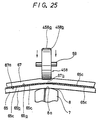
- each pressing roller as indicated at 458 on Figs. 24 and 25, may be provided with a cylindrical peripheral surface 458 a with rounded or bevelled edges 458 b at the opposite margins of the peripheral surface.
- the back-up surface 8 a can be upwardly convex, as shown, without undesirably decreasing the width of the band-shaped area at which each pressing roller 458 presses together the sheet 67 of developing paper and the photo-sensitive film 65 against the back-up surface 8 a .
- the opposite marginal portions of the back-up surface are spaced from the photo-sensitive film 65 passing thereover, as is clear in Fig. 25. It will be appreciated that the arrangement shown in Figs. 24 and 25 differs from that indicated in Fig.
- the paths P1 and P2 are established, in Fig. 23, by the guiding rollers 23 and 24 cooperating with the feed roller 9 and the tensioning roller 10, respectively, the requisite paths P1 and P2 can be established by other guiding means, for example, by guiding rollers which are apart from the rollers cooperating with the feed roller 9 and tensioning roller 10 to transport the film 65 and the sheet 67.
- Fig. 25 specifically illustrates the photo-sensitive film 65 as including a transparent film base 65 b coated, at its exposure side 65 a , with an almost infinite number of microcapsules or particles 65 c of a suitable resin which contain respective pigment precursors and which are optically hardened, for example, when irradiated with ultraviolet light of respective wavelengths.
- each sheet 67 of developing paper is shown to have the developing side 67 a coated with a developing substance or agent capable of chemically reacting with the pigment precursors released by the crushed microcapsules 65 c to provide the corresponding colour or pigments on the developing surface 67 a of the sheet 67.
- the photo-sensitive film 65 and the sheet 67 of developing paper are arranged with respect to the back-up member 7 so that the photo-sensitive film 65 which is relatively harder and more rigid than the sheet 67 of developing paper will be in contact with the back-up surface 8 a of the member 7.
- the contacting film 65 and sheet 67 are pressed together by a pressing roller 58, 158, 258, 358 or 458, the resulting reduction in thickness of the sheet 67, as at 67 b on Fig. 25, will not cause wrinkling of the underlying photo-sensitive film 65.
- the arrangement o the film 65 in contact with the fixed back-up surface 8 a serves to reduce the frictional resistance to the movement of the film 65 across the back-up surface. Therefore, the intermittent transport of the film 65 and the sheet 67 of developing paper can be effected smoothly again to avoid relative displacements or shifting of the stripe-shaped increments of the developed picture and irregular concentrations of the development.
- the above described arrangement of the film 65 and sheet 67 of developing paper presumes that the photo-sensitive film 65 is harder and has the greater rigidity.
- the sheet of developing paper 67 has the higher rigidity and hardness, for example, as when the sheet 67 of developing paper is formed of overhead projector (OHP) film, such OHP film can be arranged under the photo-sensitive film 65, and thus be in contact with the back-up surface 8 a .
- OHP overhead projector
- Self-aligning means can be provided automatically to attain a desired attitude of the peripheral surface of each pressing roller relative to the back-up surface during the transporting of the pressing roller along the back-up surface.
- the desired attitude of the peripheral surfaces 58 a and 58′ a of the rollers 58 and 58′ relative to the back-up surface 108 a is achieved by providing a carriage and roller assembly 541 with respect to the carriage 542.
- the carriage 542 is shown to include a generally block-shaped body 543 which is similar to the previously described body 43 in having parallel, spaced apart flanges 545 depending from the body 543. However, the spaced apart flanges 545 have aligned holes 546 and 546′ extending therethrough at locations that are symmetrically arranged at opposite sides of the mid-position along the length of the flanges 545.
- the pressing rollers 58 and 58′ are respectively supported by roller support arms 553 and 553′ having block-shaped major portions 553 a and 553′ a respectively.
- These major portions 553 a and 553′ a of the roller support arms are formed with respective downwardly opening central cutouts so as to divide the lower parts of the major portions 553 a and 553′ a into bifurcated depending parts 553 b and 553′ b , respectively, which are formed with aligned holes 555 and 555′ extending therethrough.
- the pressing rollers 58 and 58′ have cylindrical outer peripheral surfaces 58 a and 58′ a , and are further formed with central, axially extending bores 58 b and 58′ b which rotatably receive respective axles 59 and 59′.
- the axles 59 and 59′ are press fitted in the holes 555 and 555′ and extend loosely through the bores 58 b and 58′ b of the pressing rollers.
- the pressing rollers 58 and 58′ are rotatably supported by the arms 553 and 553′ with the lower portions of the rollers 58 and 58′ projecting downwardly from the respective support arm 553 and 553′.
- the roller support arms 553 and 553′ further have channels 554 and 554′ opening upwardly, and extending laterally across their respective upper portions, and being parallel and offset with respect to the axles 59 and 59′ on which the respective pressing rollers are rotatable.
- the channels 554 and 554′ are dimensioned loosely to receive support shafts 560 and 560′, respectively, which extend through and can turn in the holes 546 and 546′, respectively, formed in the flanges 545.
- the support shafts 560 and 560′ have diametrically extending bores 560 a and 560′ a formed therethrough for alignment with apertures 554 a and 554′ a formed in support arms 553 and 553′ at opposite sides of the middle portions of the channels 554 and 554′, respectively.
- Self-aligning shafts 557 and 557′ are press-fitted in the diametrically extending bores 560 a and 560′ a and turnably received in the apertures 554 a and 554′ a respectively.
- the upper surfaces of the main portions 553 a and 553′ a of the roller support arms 553 and 553′ are formed with shallow circular recesses 556 and 556′ in which the lower ends of the compression springs 63 and 63′ are respectively seated.
- the pressing rollers 58 and 58′ are rotatably supported by the arms 553 and 553′ with the rollers 58 and 58′ being arranged in tandem and movable independently of each other substantially in the vertical direction relative to the carriage body 543 by pivoting of the support arms 553 and 553′ about the axes of the support shafts 560 and 560′, respectively. Further, the support arms 553 and 553′ are mounted for angular displacements independently of each other relative to the respective support shafts 560 and 560′ about the axes of the self-aligning shafts 557 and 557′, respectively.
- the pressing rollers can be individually inclined in one direction or the other relative to the back-up surface on the member 107, as indicated by the dot-dash lines in Fig. 27, thereby automatically attaining a desired attitude of the peripheral surface of each pressing roller relative to the back-up surface.
- the spring bearings 61 and 61′ are positioned to compress the springs 63 and 63′ so that they urge the roller support arms 553 and 553′ to rock downwardly about the shafts 560 and 560′ and thereby urge the pressing rollers 58 and 58′ downwardly against the upper surface 108 of the back-up member 107 when an upper frame structure of the apparatus 1E corresponding to the previously described frame structure 16 is similarly locked in its operative position.
- the springs 63 and 63′ acting on the support arms 553 and 553′ urge the support arms to shift angularly about the shafts 557 and 557′ so as to stabilise the attitudes of the pressing rollers 58 and 58′ in positions where the pressure resulting from the springs 63 and 63′ is applied to the back-up surface 108 uniformly across the width of each of the rollers 58 and 58′ in a direction precisely perpendicular to the surface 108.
- the attitudes of the pressing rollers 58 and 58′ are automatically adjusted by the relative contact between the pressing rollers and the back-up surface in directions perpendicular to such back-up surface.
- Such automatic adjustment or self-alignment of the pressing rollers 58 and 58′, with respect to the back-up surface 108 makes it unnecessary to maintain absolutely precise accuracy in the manufacture and assembly of the various parts of the apparatus 1E and thereby reduces the cost of its manufacture while ensuring its satisfactory operation.
- FIG. 29 Another embodiment which is capable of achieving self-alignment of the pressing rollers 58 and 58′ with respect to the back-up surface 108 on the back-up member 107 will now be described with reference to Figs. 29, 30 and 31.
- the developing apparatus 1F shown in Figs. 29, 30 and 31 is similar to the apparatus 1 previously described in detail with reference to Figs. 6 to 14 and differs substantially therefrom only in respect of the structural provisions for achieving the self-alignment. More specifically, in the apparatus 1F, the guide shafts 22, which are fixed at their ends to the side walls 17 and 17′ of the upper frame structure 16 in the apparatus 1, are replaced by similar guide shafts 622 extending parallel to each other within a tiltable frame 623. More specifically, as shown in Fig.
- the frame 623 is rectangular and elongate in the lateral direction, that is, in the direction parallel to the longitudinal axis of the back-up member 107.
- the frame 623 is shown to include elongate parallel side members 623 a connected, at their ends, to cross members 623 b to which the ends of the guide shafts 622 are attached.
- Pivot pins 624 extend centrally from the cross members 623 b and are rotatably received in suitable bearings 625 (Fig. 29) provided in the side walls 17 and 17′ of the frame structure 16.
- the frame 623 is tiltable about an axis parallel to the longitudinal axis or median of the back-up surface 108, and such tilting of the frame 623 may be suitably limited by stop pins 626 projecting inwardly from the side walls 17 and 17′ below the cross members 623 b and being engageable by the cross members upon a predetermined inclination of the frame 623 from the horizontal.
- the carriage and roller assembly 41 may again be similar to that described with reference to the apparatus 1 and is guided by its grooved guide rollers 51 for movements along the guide shafts 622.
- the pressing rollers 58 and 58′ are spring urged against the back-up surface 108 and, in reaction thereto, the carriage 42 is spring biased upwardly to maintain the guide rollers 51 in rolling contact with the guide shafts 622.
- the tiltable frame 623 is angularly adjusted about the axis defined by the pivot pins 624 so as to achieve the desired attitude of the rollers 58 and 58′ relative to the back-up surface 108.
- the tiltable frame 623 is automatically urged to a position in which the peripheral surfaces of the pressing rollers 58 and 58′ apply pressure uniformly to the back-up surface 108 across the width of each of the pressing rollers and in a direction perpendicular to the back-up surface 108.
- the apparatus 1G differs from the apparatus 1 described with reference to Figs. 6 to 14 in that the shafts 59 and 59′ of the pressing rollers 58 and 58′ may be mounted directly in suitable holes in depending flanges 745 of a body 743 of a carriage 742.
- the carriage and roller assembly 741 of the apparatus 1G is merely guided by the guide shafts 22 (not shown on Figs. 32 and 33) and no springs are present within the assembly 741 to urge the pressing rollers 58 and 58′ downwardly relative to the carriage body 743.
- the fixed back-up member 7 of the apparatus 1 is replaced by a floating back-up member 707 which is spring urged upwardly against the peripheries 58 a and 58′ a of the pressing rollers.
- the floating back-up member 707 has a hard metal body 707 a provided with an approximately square cross section for high rigidity and formed with a back-up surface 708 and flanges 707 b projecting laterally along its opposite sides.
- a rigid, elongate support plate 709 extends laterally between the side walls 4 and 4′ of the lower frame structure 2 and is securely attached thereto.
- Guide pins 710 with heads 710 a at their upper ends extend from the support plate 709 in uniformly spaced apart rows at opposite sides of the body 707 a of the floating back-up member 707.
- the flanges 707 b are provided with suitably spaced apart holes 707 c through which the guide pins 710 loosely extend with the heads 710 a situated above the flanges 707 b .
- helical compression springs 711 are provided around the guide pins 710 between the support plate 709 and the flanges 707 b so as to urge the back-up member 707 to a raised position shown in dot-dash lines at 707′ in Fig. 33, and at which the flanges 707 b abut against the heads 710 a of the guide pins.
- the various parts of the apparatus 1G are dimensioned so that, when the movable upper frame structure thereof (not shown) which corresponds to the frame structure 16 of the apparatus 1, is locked in its horizontal operative position, the pressing rollers 58 and 58′ act against the back-up surface 708 at the top of the back-up member 707 so as to push the back-up member 707 downwardly a small distance, for example, to the position indicated in full lines on Fig. 33, against the forces of the springs 711. Accordingly, the back-up surface 708 is continuously urged, by the forces of the springs 710, against the peripheries 58 a and 58′ a of the pressing rollers 58 and 58′.
- the back-up member 707 is free to be urged to any attitude in which there will be uniform pressure distribution between the back-up surface 708 and the peripheral surfaces 58 a and 58′ a of the pressing rollers across the entire axial widths of such rollers.
- each apparatus 1E, 1F or 1G by reason of its described self-aligning feature, ensures that, as the rollers 58 and 58′ are moved across the superposed sheet 67 of developing paper and photo-sensitive film 65 against the respective back-up surface, the pressure is applied uniformly to the sheet 67 and the film 65 across the entire width of each pressing roller thereby to ensure that irregular concentration of development will be avoided. Furthermore, by reason of the self-aligning feature, the desired contact between the back-up surface and the peripheries of the pressing rollers can be reliably achieved without requiring extreme accuracies and care in the manufacture and assembly of the apparatus.
- a developing apparatus 1H is shown to be generally similar to the apparatus 1 described with reference to Figs. 6 to 14 and differs substantially therefrom only in respect of the structures provided in the apparatus 1H to define a back-up surface to support the photo-sensitive film 65 and the sheet 67 of developing paper during the pressing together thereof, and the structure provided to effect intermittent transport of the film 65 and the sheet 67 across such back-up surface.
- a back-up member 800 is provided in the form an elongate cylindrical body 801 which, at its periphery defines a cylindrical back-up surface 802 having an axial length slightly longer than the width of the photo-sensitive film 65 and the sheet 67 of developing paper which are to be pressed together between the pressing rollers 58 and 58′ and the back-up surface 802.
- the back-up member 800 which also serves as part of structure for feeding the film 65 and sheet 67, as hereinafter described, has reduced diameter end portions 803 extending axially from the opposite ends of the cylindrical body 801 and terminating in trunnions 804 and 804′ which are journalled in bearings 805 and 805′, respectively, fixedly supported by the side walls 4 and 4′ of the lower frame structure 2 (Fig. 35).
- the bearings 805 and 805′ are positioned so that the axis of the cylindrical back-up member 800 will extend horizontally in a vertical plane that substantially bisects the peripheral surfaces 58 a and 58′ a of the rollers 58 and 58′ as the rollers are moved with the carriage and roller assembly 41 along the guide shafts 22.
- the trunnion 804′ received in the bearing 805′ extends axially therethrough and has a driven gear 806 fixed thereto.
- a drive assembly 807 is provided for the cylindrical back-up member 800 and may include a so-called stepping motor 808 secured on the base 3 adjacent the side wall 4′ and having a driving gear 809 fixed to a motor shaft 808 a which is suitably rotatably mounted on the adjacent side wall 4′ so as to also be in meshing engagement with the driven gear 806.
- the reduced diameter end portions 803 of the cylindrical back-up member 800 are provided with axial dimensions substantially larger than the width of the carriage and roller assembly 41 and, as hereinafter described, provide stand-by positions for the assembly 41 during the intermittent advancements of the film 65 and sheet 67 across the back-up surface 802. Further, as is particularly shown in Fig. 34, the cylindrical back-up surface 802 on the member 800 has rounded edges 802 a at the opposite ends thereof for a purpose hereinafter described.
- the paper discharge guide plate 70 extends forwardly from adjacent the cylindrical back-up surface 802 on the back-up member 800 in a substantially horizontal plane that is below the tangent to the surface 802 at the top thereof (Fig. 37).
- a paper and film feed guide plate 811 is also provided in the apparatus 1H and extends between, and is connected to the side walls 4 and 4′ of the lower frame structure 2 behind the cylindrical back-up member 800. As shown in Fig. 37, the feed guide plate 811 is disposed beneath the path of the photo-sensitive film 65 running forwardly from the guide roller 66 to the back-up surface 802 at a position below the top of the back-up surface.
- guiding or pinch rollers 812 and 813 are provided to cooperate with the cylindrical back-up surface 802 of the rotatable back-up member 800 to wrap the photo-sensitive film 65 and the sheet of developing paper 67 in contact with each other about an upper portion of the circumference of the back-up surface 802, and to cause intermittent transport of the film 65 and the sheet 67 across the back-up surface in response to incremental or step-by step rotation of the member 800.
- the guiding and pinching rollers 812 and 813 are shown to be of substantially the same length as the cylindrical body 801 of the member 800 and extend parallel to the axis of the member 800 in front of and behind, respectively, a vertical plane passing through the axis of the member 800, and equally distances from that vertical plane.
- the rollers 812 and 813 are rotatable on shafts 812 a and 813 a , respectively, which project axially beyond the respective rollers, and which are supported, at their opposite ends by support arms 814 and 814′ and support arms 815 and 815′, respectively.
- the arms 814 and 814′ extend substantially horizontally forward from pivot pins 816 and 816′ which are carried by the side walls 17 and 17′ of the upper frame structure 16 and which are located so that the roller 812 will be positioned to bear downwardly against the back-up surface 802 at a position behind the vertical plane containing the axis of rotation of the member 800, and hence at a position below the summit or longitudinal median of the back-up surface 802 at the top of the cylindrical body 801.
- the support arms 815 and 815′ are similar pivotably supported on, and extend substantially horizontally rearwardly from pivot pins 817 and 817′ which are carried by the side walls 17 and 17′, respectively.
- the pivot pins 817 and 817′ are located at about the same level as the pivot pins 816 and 816′ and positioned so that the roller 813 can bear downwardly against the back-up surface 802 in front of the vertical plane passing through the axis of the member 800 and slightly below the summit of the cylindrical back-up surface 802, that is, the longitudinal median of the effective back-up surface.
- each of the support arms 814, 814′, 815 and 815′ is urged downwardly about its respective pivot pin 816, 816′, 817 and 817′ by a respective torsion spring 818.
- each of the torsion springs 818 has a coil portion 818 a extending around the respective pivot pin 816, 816′ 817 or 817′, and angularly related arms 818 b and 818 c extending from the opposite ends of a coil portion 818 a and being relatively resiliently urged by the latter so as to increase the angular distance between the arms 818 b and 818 c .
- each torsion spring 818 engages the respective support arm 814, 814′, 815 or 815′, and the arm 818 c of each torsion spring acts against a respective spring anchor 819 which is suitably secured to the adjacent side wall 17 or 17′.
- the rollers 812 and 813 are pressed downwardly against the back-up surface 802 when the movable upper frame structure 16 is displaced to its operative horizontal position shown in full lines in Fig. 37.
- the apparatus 1H is similar to the apparatus 1 of Figs. 6 to 14 and has its carriage and roller assembly 41 positioned by the guide shafts 22 so that the pressing rollers 58 will be pressed downwardly toward the back-up surface 802 at the longitudinal median line thereof midway between the guiding and pinch rollers 812 and 813, as clearly shown in Fig. 37.
- the apparatus 1H may also have its operations controlled by a circuit similar to that shown in Fig. 13, but in which the motor 11 provided for driving the feed roller 9 and the tensioning roller 10 of the developing apparatus 1 is replaced by the motor 808 of the drive mechanism 807 for the rotatable back-up member 800 in the apparatus 1H.
- the carriage and roller assembly 41 is disposed at one or the other of its ends or stand-by positions corresponding to the reduced diameter end portions 803 of the back-up member 800 so that the pressing rollers 58 and 58′ of the assembly 41 are then fully disengaged from any surface of the back-up member 800 to avoid any interference with turning of the back-up member.
- the carriage and roller assembly 41 waits at one of its end or stand-by positions, the stepping motor 808 of the drive 807 is suitably operated to turn the back-up member 800 in the clockwise direction, as viewed in Fig. 37.
- the rollers 812 and 813 are frictionally driven in the counter-clockwise direction, as viewed in Fig. 37.
- the photo-sensitive film 65 which has been initially threaded between the roller 812 and the back-up member 800, and then between the roller 813 and the back-up member 800, is intermittently transported past the FOT 15 so that the exposure side 65 a of the film is exposed line-by-line to light passing through the transparent base of the film so as to provide an exposure of the desired picture on a prescribed area or frame of the film 65.
- a sheet 67 of developing paper is supplied from the tray 68 so as to overlap the exposed frame of the film in correct registration therewith and to be fed together with the film 65 between the roller 812 and the back-up surface 802, and then toward the summit or longitudinal median of the back-up surface 802 which is vertically aligned with the axis of rotation of the member 800.
- the arrival of the leading end of the exposed frame of the photo-sensitive film 65 at the longitudinal median of the back-up surface 802 is detected by a suitable sensor (not shown) to provide a start signal by which the flip-flop circuit 75 causes the motor drive circuit 76 to effect operation of the motor 29 in the direction for moving the carriage and roller assembly 41 away from the end or stand-by position at which it resided while awaiting the arrival of the exposed frame of the film.
- the carriage and roller assembly 41 is moved parallel to the guide shafts 22, that is, parallel to the axis of the back-up member 800 so that the rollers 58 and 58′ move from a stand-by position free of the back-up member 800 onto the back-up surface 802, the tandem arranged pressing rollers 58 and 58′ roll over the rounded edge 802 a at the respective end of the back-up surface 802, thereby to avoid excessive noise and resistance to the movement of the pressing rollers 58 and 58′ from the stand-by position thereof onto the back-up surface 802 where the pressing rollers 58 and 58′ roll parallel to the axis of the member 800 and thereby press together the sheet 67 of developing paper and the photo-sensitive film 65 against the back-up surface 802.
- the rollers 58 and 58′ are again out of engagement with the member 800, the sensor 36 or 37 detects the arrival of the assembly 41 at such other end position and provides a signal of logic level [1] through the OR circuit 74 to the flip-flop 75 to invert the polarity of the output from the flip-flop circuit.
- the signal of logic level [1] from the sensor 36 or 37 triggers the respective monostable multi-vibrator 71L or 71R, and the resulting output from the triggered monostable multi-vibrator is passed through the OR circuit 72 to the motor drive circuit 76 to inhibit any operation of the motor 29 for the duration of such pulse.
- the carriage and roller assembly 41 remains at rest at one or the other of its stand-by or end positions, while the motor drive circuit 73 responds to such pulse to cause operation of the stepping motor 808 by which a further increment of movement of the sheet 67 together with the film 65 is effected in response to corresponding angular displacement of the back-up member 800.
- the absence of any pulse fed from the OR circuit 72 to the motor drive circuit 76 enables the circuit 76 to effect renewed operation of the motor 29 in the direction corresponding to the polarity of the output then being received by the motor drive circuit 76 from the flip-flop circuit 75.
- the carriage and roller assembly 41 is moved laterally or returns to its original end or stand-by position and, during such movement, the rollers 58 and 58′ again press together the sheet 67 of developing paper and the photo-sensitive film 65 against the back-up surface 802 in another band-shaped pressing area that abuts or partially overlaps the band-shaped area in which the sheet 67 and film 65 were previously pressed together.
- each traverse of the sheet 67 and the film 65 by the rollers 58 and 58′ causes a band-shaped part of the image or picture to be printed or developed on the sheet 67.
- the pressing rollers 58 and 58′ successively press together the same band-shaped area of the photo-sensitive film 65 and the sheet 67 of developing paper against the back-up surface 802 by rolling thereacross in tandem, the area at which each of the rollers 58 and 58′ contacts the sheet 67 at any one time is very small so that the force exerted by the springs 63 and 63′ of the carriage and roller assembly 41 may be as small as 2 to 3 kg, as compared with the force of 1,000 to 1,500 kg required for pressing together the roller e and f in the apparatus shown in Fig. 1.
- the sheet 67 of developing paper and the photo-sensitive film 65 are transported by rotation of the back-up member 800, no friction occurs between the sheet 67 and the film 65, and the back-up surface 802 on the rotated member 800 so that the sheet 67 and the film 65 are always transported through the correct incremental distance and with high accuracy. Since the incremental amount of movement of the sheet 67 and the film 65 is regular for the successive feeding periods, the successive band-shaped areas at which the pressing rollers 58 and 58′ press together the sheet 67 and the film 65 against the back-up surface 802 are of regular width to ensure clear and uniform development of the picture or image.
- the back-up member 800 is electromagnetically locked against rotation in the intervals when the motor 808 is not operated, that is, when the carriage and roller assembly 41 is being laterally moved across the superposed sheet 67 and film 65 against the back-up surface 802.
- a worm gear mechanism may be interposed in the transmission between the motor 808 and the back-up member 800.
- Either the peripheral surface of a pressing roller or a back-up surface between which a sheet of developing paper and a photo-sensitive film are pressed together can be formed with minute concave and convex surface irregularities distributed thereover so that the force urging the pressing roller toward the back-up surface causes contact pressures to be applied to the sheet of developing paper and the photo-sensitive film primarily at the localised areas defined by the convex surface irregularities.
- a back-up member 907 that can be used in place of the back-up member 7 in the apparatus 1 of Figs. 6 to 14.
- the back-up member 907 is similarly shown to have a top surface 908 divided to provide a back-up surface 908 a having a length, measured in the lateral direction of the developing apparatus, corresponding to the widths of the sheets of developing paper and photo-sensitive film to be employed in the apparatus, and stand-by surfaces 908 b extending from the opposite ends of the back-up surface 908 a and raised relative to the back-up surface to define guide shoulders 908 c at the ends of the back-up surface 908 a .
- stand-by surfaces 908 b extending from the opposite ends of the back-up surface 908 a and raised relative to the back-up surface to define guide shoulders 908 c at the ends of the back-up surface 908 a .
- guide shoulders 908 c at the ends of the back-up surface 908 a .
- the top surface 908 of the back-up member 907 is generally flat and has bevelled or rounded edges 908 d extending along its opposite longitudinal margins. Furthermore, the back-up surface 908 a is formed with a large number of parallel grooves 909 extending lengthwise along the back-up surface 908 a .
- Such grooves 909 which are desirably of V-shaped cross section, are of a size generally corresponding to the resolution of a picture to be developed, for example, from 100 ⁇ m to about 200 ⁇ m.
- the grooves 909 may be provided with a pitch p of about 200 ⁇ m and with a depth of substantially twice the pitch p .
- the pitch p of the grooves 909 may be high than 200 ⁇ m when the required resolution is not too high.
- the parallel V-shaped grooves 909 define protrusions 910 (Fig. 39) therebetween, and such protrusions 910 are of inverted V-shaped cross section.
- the described grooves 909 and the intervening protrusions 910 may be manufactured, for example, through the use of a laser beam.
- the alternating grooves 909 and protrusions 910 form minute concave and convex surface irregularities distributed across the back-up surface 908 a .
- a pressing roller 58 or 58′ having a cylindrical peripheral surface presses a sheet 67 of developing paper and an underlying photo-sensitive film 65 against the back-up surface 908 a while rolling along the back-up surface in the longitudinal direction of the back-up member 907, the resulting contact pressures are concentrated at the regions corresponding to the ridges of the protrusions 910.
- the pressure exerted on each of the microcapsules 65 c of the film 65, which microcapsules correspond, in size, to the desired resolution, is very substantially increased so that the rupture of the non-hardened microcapsules is ensured.
- the back-up member 907 described with reference to Figs. 38 and 39 is further advantageous as compared with a back-up member having a flat back-up surface, for example, as in the previously proposed apparatus illustrated by Fig. 4.
- the pressing roller l will concentrate the pressure applied to the sheet d and film c at those areas of the irregular surface g ′ that are relatively high.
- the contact pressure is concentrated at the peaks or ridges of the protrusions 910 distributed across the entire width of the back-up surface so that the sheet 67 and film 65 are uniformly pressed together across the entire width of the band-shaped pressing area to ensure uniform concentration of the development.
- a back-up member 907′ with a back-up surface 908′ a having a multitude of small holes or pits 909′ formed, for example, by etching, in the surface 908′ a and being randomly distributed thereover with a predetermined spacing, for example, of about 100 ⁇ m to 200 ⁇ m.
- the back-up surface 908′ a again has minute concave and convex surface irregularities distributed thereover and defined by the holes or pits 909′ and the spaces therebetween.
Landscapes
- Physics & Mathematics (AREA)
- General Physics & Mathematics (AREA)
- Photographic Developing Apparatuses (AREA)
- Delivering By Means Of Belts And Rollers (AREA)
Abstract
Description
- The invention relates to developing apparatus and particularly to apparatus to develop an image or picture on a sheet of developing paper from an exposed sheet of photo-sensitive material by pressing together the sheets.
- It has been previously proposed in Japanese laid-open Patent Gazette No. 59-30537, to print or develop a colour picture on a sheet of developing paper from a sheet of photo-sensitive material having a coating of photo-sensitive microcapsules which have been irradiated with a light image of the picture. This known printing method employs, as the photo-sensitive sheet, a base made of a suitable resin on which there is a coating of uniformly distributed yellow, magenta and cyan microcapsules. Each of the yellow, magenta and cyan microcapsules has an outer shell of a relatively soft material in which there is sealed an optically-hardenable composition containing a respective pigment or a precursor thereof. When the photo-sensitive microcapsules are irradiated with respective wave lengths of light, the optically-hardenable compositions therein are selectively hardened. For example, irradiation with blue light hardens the yellow microcapsules containing the precursor of yellow pigment, irradiation with green light hardens the magenta microcapsules containing the precursor of magenta pigment and irradiation with red light hardens the cyan microcapsules containing the precursor of cyan pigment.
- It will be appreciated that, when irradiating the above described sheet of photo-sensitive material with a light image of a colour picture, the light of the colour picture is suitably analyzed into the three primary colours of red, green and blue and the sheet of photo-sensitive material is irradiated separately with a red light image, a green light image and a blue light image by which the cyan, magenta and yellow microcapsules, respectively, are selectively hardened in accordance with such images. Then, the irradiated or exposed coating of photo-sensitive microcapsules on the sheet of photo-sensitive material is placed in contact with a sheet of developing paper coated with or containing a developing substance, and the contacting sheets are pressed together so as to rupture the shells of the yellow, magenta and cyan microcapsules that were not substantially hardened by irradiation with light of corresponding wave lengths. The substances containing precursors of pigments are transferred from the ruptured microcapsules to the facing surface of the sheet of developing paper and react with the developing substances thereon to develop the respective colour pigments from the precursors thereof. Thus, the transferred precursors of pigments from the yellow, magenta and cyan microcapsules are developed into the respective pigments which are suitably mixed to present a printed colour picture on the sheet of developing paper.
- In a previously proposed apparatus for pressing together the sheets of developing paper and photo-sensitive material, shown at a on Figure 1 of the accompanying drawings, a sheet c of a photo-sensitive material, which is desirably in the form of a long web or film, and a sheet d of the developing paper are pressed together between a pair of vertically superposed cylindrical pressure rollers e and f having axial lengths somewhat greater than the width of the sheets c and d. The lower pressure roller e is rotatably mounted in a suitable support frame (not shown) and rotated by a motor (also not shown). The upper pressure roller is rotatably mounted in a vertically movable frame which is pressed downward by one or more strong resilient members (not shown) so that the roller f is pressed downwardly against the roller e. A frame or area of the web or sheet c of photo-sensitive material is exposed to a light image before being brought together with the sheet d of developing paper, whereupon the sheets c and d are fed together between the pressure rollers e and f. As the lower roller e is rotated, the upper roller f pressed thereagainst is also rotated so that the sheet c of photo-sensitive material and the sheet d of developing paper are moved together while being pressed between the rollers e and f.
- The apparatus a has the advantage of providing a relatively high printing speed since the sheets of the developing paper and the photo-sensitive material are pressed together while being continuously transported or advanced by the rotated rollers e and f. However, in the apparatus a, the rollers e and f act to press together the sheets c and d simultaneously along a stripe-like area extending across the entire width of the sheets. Therefore, in order to provide the requisite pressure at each increment of such stripe-like area to ensure rupture of those microcapsules that have not been fully hardened, and further to ensure transfer of the precursors of pigments from the ruptured microcapsules to the sheet of developing paper, a very large force must be provided to urge the roller f toward the roller e. For example, in order to rupture the unhardened microcapsules of the sheet of photo-sensitive material and to ensure adequate contact of the released pigment precursors with the developing substances on the sheet of developing paper, it is necessary that the sheet c of photo-sensitive material and the sheet d of developing paper be pressed together with a pressure of 30 to 40 kg/mm². In the case where, for example, a picture is to be printed on a sheet of developing paper of A4 size which has a width of 21 cm, and the rollers e and f employed to press together the sheets c and d each have a diameter of 50 mm, the force urging together the rollers has to be about 57 kg for each cm of roller length, that is, a total force of about 1200 kg for rollers having lengths of 21 cm. The apparatus a, in order to be capable of applying such a large force to urge together the rollers e and f, must be massive and requires a high-powered motor and a transmission mechanism to transmit the torque to the lower pressure roller e. As a result of the foregoing, the apparatus a is relatively expensive and difficult to assemble and maintain.
- In order to overcome the foregoing disadvantages of the known apparatus a, apparatus b has been proposed which, as shown in Figure 2, comprises a fixed back-up member g defining an upwardly facing back-up surface g′, and a pressure member h having a spherical ball i rotatably mounted at its lower end. The sheets c and d of the photo-sensitive material and the developing paper, respectively, are brought into contact with each other and transported intermittently across the back-up surface g′ in a direction of sheet travel that is transverse to the length of the back-up surface g′. The pressing member h is mounted for reciprocal movements in the direction along the back-up surface g′. The pressing member h is mounted for reciprocal movements in the direction along the back-up g′, that is, perpendicular to the direction of sheet travel, between terminal positionsh₁ and h₂, shown in dotted-lines in Figure 2, and at which the pressing member h is situated laterally beyond the side edges of the sheets c and d. During its movements between the terminal positions h₁ and h₂, which occur when the sheets c and d are at rest on the back-up surface g′, the pressing member h is urged downwardly so that the ball i exerts pressure to urge together the sheets c and d against the back-up surface g′ progressively along a narrow pressing region extending across the entire width of the contacting sheets c and d. The described pressing step is effected repetitively with intervening sheet transporting steps during each of which the sheets c and d are incrementally advanced.
- Since the ball i of the pressing member h acts, at any time, against only a very small area of the contacting sheets c and d, the requisite pressure to ensure the rupture of the unhardened microcapsules and the transfer of the released pigment precursors into adequate contact with the developing substances can be achieved with only a moderate force urging the pressing member h toward the back-up surface g′. Thus, the apparatus b is disadvantageous in that its printing speed is low because developing of the picture is effected by alternating the movements of the pressing member h across the contacting sheets c and dand the intermittent transport of the sheets c and d of the photo-sensitive material and the developing paper. Furthermore, as shown in Figure 3A, the contact pressure between the ball i of the pressing member h and the back-up surface g′ is not uniform across the width w of the pressing area, as indicated by the pressure distribution curve j. As will be apparent from such curve j, the contact pressure between the ball i and the back-up surface g is highest at the centre of the ball and is reduced therefrom toward the opposite sides of the pressing area.
- Therefore, the pressure urging together the sheet c of photo-sensitive material and the sheet d of developing paper d is highest at the centre of the pressing area and progressively reduces towards the opposite margins of such area. Therefore, for any particular degree of exposure, more of the microcapsules will be ruptured to release the respective pigment precursors along the center of the passing area than along the opposite side margins thereof. Thus, the concentration of development on the sheet d of developing paper is highest at the centre of each of the stripe-like pressing regions and is gradually reduced or diminished toward the opposite edges of each such pressing region or area, as indicated by the successive concentration distribution curves k in Figure 3B. If the sheets c and d are intermittently transported through an incremental distance of pitch equal to the width w of the tripe-like area of contact of the ball i with the sheet d of developing paper, the printed or developed picture will have a striped pattern resulting from the irregular concentration of development.
- If the incremental movements of the intermittently transported sheets c and d are reduced, for example, if each incremental movement of the sheets c and d is made equal to about one half the width w of the stripe-like area of contact of the ball i with the sheet d of the developing paper, the pressing member h will act on the sheets c and d along overlapping pressing areas with the result that the developed or printed picture will have a more uniform concentration of development on the sheet d of developing paper, as indicated by the concentration distribution curves k in Figure 3C. However, such reduction of the incremental movements of the sheets c and d will very substantially increase the printing or developing time and thereby considerably reduce the printing speed.
- In order to reduce the force that needs to be exerted to press together the sheets c and d, as compared with the apparatus a of Figure 1, while increasing the width of the pressing area along which the sheets c and d are pressed together during each stroke or scan across the width thereof, as compared with the apparatus b of Figure 2, is has been proposed in Japanese Patent Application No. P270758/87, filed October 27, 1987 to replace the pressing member h having a rotatable ball i to contact the sheet d of developing paper, by a rotatable roller l (Figure 4) disposed in opposing relation to the back-up surface g′ and having an axis of rotation extending parallel to the direction of travel of the sheets c and d across the back-up surface g′. The roller l has a cylindrical peripheral surface and is mounted for bodily movements relative to the back-up member g parallel to the back-up surface g′ in directions perpendicular to the direction of intermittent sheet travel, and during such movements of the roller l, the roller l is urged toward the back-up surface g′ with the sheets c and d of photo-sensitive material and developing paper being in contact with each other between the roller l and the back-up surface g′ so as to be pressed together thereby. By reason of the cylindrical peripheral surface of the roller l, the width of the strip-like pressing area along which the sheets c and d are pressed together sufficiently uniformly to develop the picture can be substantially increased. Therefore, the printing or developing speed can be increased relative to that of the apparatus b of Figure 2.
- In the apparatus of Figure 4, during each incremental movement of the sheets c and d, the roller l is moved off the contacting sheets c and d to a standby position on the back-up surface g′ at one side or the other of the sheets c and das shown in Figure 5. At the completion of each incremental movement of the sheets c and d, the roller l is moved from its standby position on the back-up surface g′ at one side of the path of travel of the sheets c and d laterally across the contacting sheets in a pressing step to a standby position onto back-up surface g′ adjacent the opposite sides of the sheetsc and dwhereupon an incremental movement of the sheets c and d is effected in another sheet transporting step. Thus, the sheet pressing and transporting steps are alternately performed in a repetitive manner and, due to the relatively wide area along which the roller l can exert the requisite pressure against the contacted sheets c and d during each pressing step, a sufficiently high printing or developing speed can be realised. However, the contacting sheets c and d have a substantial thickness and, as shown in Figure 5, the opposite edges of the contacting sheets extend upwardly from the back-up surface g′ at the standby positions of the roller l. Therefore, each time the roller l is rolled onto or off the contacting sheets c and dm or to, respectively, a standby position of the roller on the back-up surface g′, the roller l, in effect, rolls over a step and thereby generates objectionable noise. Further, there is the likelihood that, in moving from a standby position on the back-up surface g′ onto the contacting sheets c and d, the roller l will damage the side edges of the developing paper and the photo-sensitive material, or even that the roller l, in colliding with the raised side edges of the sheets c and dwill have its rolling movement halted thereby.
- According to one aspect of the invention there is provided apparatus to develop an image on a sheet of developing paper from a sheet of photo-sensitive material of a kind which develops the image upon the pressing together of the sheets of developing paper and photo- sensitive material, the apparatus comprising:
a back-up member having a back-up surface and standby surfaces extending from the opposite ends of the back-up surface and being raised relative to the backup surface to define guide shoulders at the ends of the back-up surface;
means intermittently to transport the sheets of developing paper and photo-sensitive material in contact with each other across the back-up surface between the guide shoulders in a predetermined direction of sheet travel at a substantial angle to a longitudinal median of the back-up surface;
at least one rotatable roller disposed in opposing relation to the back-up surface and having an axis of rotation substantially at right angles to the longitudinal median of the back-up surface;
means to mount the roller for bodily movements relative to the back-up member toward and away from the back-up surface and parallel to the back-up surface in directions parallel to the longitudinal median thereof;
means to transport the roller relative to the back-up member in said directions parallel to the longitudinal median from one to another of the standby surfaces while urging the roller toward the back-up surface with the sheets of developing paper and photo-sensitive material in contact with each other between the roller and the back-up surface so as to be pressed together thereby; and
control means to cause coordinate operations of the means intermittently to transport the sheets and the means to transport the roller so that the sheets are transported a predetermined incremental distance in the direction of sheet travel while the roller is situated on one of the standby surfaces and the sheets are at rest while the roller is transported along the back-up surface from one to another of the standby surfaces. - Such apparatus can be of relatively small size and low cost while reliably achieving developing of the picture at an acceptably high speed. A uniform developing concentration can be obtained and damage to the sheets of developing paper and photo-sensitive material and generation of objectionable noise during operation of the apparatus can be avoided.
- The sheets of developing paper and photo-sensitive material in contact with each other can be intermittently transported in a predetermined direction of sheet travel across the back-up surface and, during each interval when the sheets are at rest on the back-up surface, the rotatable roller can be transported along the back-up surface at a substantial angle to the direction of sheet travel while being urged toward the back-up surface to press together the sheets between the roller and back-up surface. The back-up surface can have raised guide shoulders at its opposite ends to guide the adjacent side edges of the sheets and thereby prevent relative shifting thereof during pressing together of the sheets or the intermittent transport thereof.
- Two contacting sheets, for example, of developing paper and photo-sensitive material, respectively, which are of different hardness or rigidity, can be transported, in contact with each, across a curved back-up surface without being displaced relative to each other.
- The pressure exerted on the contacting sheets of developing paper and photo-sensitive material between a back-up surface and a roller transported there-across can be substantially uniformly distributed so as to achieve clear development of a picture without irregular concentrations of the development thereof.
- Self-alignment can be achieved with respect to the back-up surface and roller between which the contacting sheets of developing paper and photo-sensitive material are pressed together, thereby reducing the accuracy required in the assembly and adjustment of the respect parts.
- The force required to press together the sheets of developing paper and photo-sensitive material against the back-up surface can be minimized so as to make possible the provision of a relatively low cost apparatus that is compact and light in weight.
- The frictional resistance to the intermittent transportation of the sheets of developing paper and photo-sensitive material across the back-up surface can be minimized so as to avoid irregular movements of the sheets that would adversely affect uniform development.
- According to another aspect of the invention there is provided apparatus to develop an image on a sheet of developing paper from a sheet of photo-sensitive material which is more rigid than the sheet of developing paper and of a kind which develops the image upon pressing together of the sheets of the developing paper and the photo-sensitive material, the apparatus comprising:
means defining a back-up surface having a longitudinal median;
means intermittently to transport the sheets of the developing paper and the photo-sensitive material in contact with each other across the back-up surface in a predetermined direction of sheet travel which is at a substantial angle to the longitudinal median thereof, and, with the sheet of photo-sensitive material contacting the back-up surface;
at least one rotatable roller disposed in opposing relation to the back-up surface and having an axis of rotation substantially at right angles to the longitudinal median of the back-up surface;
means to mount the roller for bodily movements toward and away from the back-up surface and parallel to the back-up surface in directions parallel to the longitudinal median thereof; and
means to transport the roller relative to the back-up surface in the directions parallel to the longitudinal median while urging the roller toward the back-up surface with the sheets of the developing paper and the photo-sensitive material in contact with each other between the roller and the back-up surface so as to be pressed together by the roller acting on the relatively less rigid sheet of the developing paper. - According to yet another aspect of the invention there is provided apparatus to develop an image on a sheet of developing paper from a sheet of photo-sensitive material of a kind which develops the image upon the pressing together of the sheets of the developing paper and the photo-sensitive material, the apparatus comprising:
means defining a back-up surface having a longitudinal median;
means intermittently to transport the sheets of the developing paper and the photo-sensitive material in contact with each other in a predetermined direction of sheet travel across the back-up surface;
at least one rotatable roller disposed in opposing relation to the back-up surface and having an axis of rotation extending at right angles to the longitudinal median;
means mounting the roller for bodily movements toward and away from the back-up surface and parallel to the back-up surface in directions parallel to the longitudinal median of the back-up surface; and
means to transport the roller across the back-up surface in the directions parallel to the longitudinal median while urging the roller toward the back-up surface with the sheets of the developing paper and the photo-sensitive material being in contact with each other between the roller and the back-up surface so as to be pressed together thereby;
the back-up surface of the roller being configured so that, during the transport of the roller across the back-up surface, the contact pressure between the peripheral surface of the roller and the back-up surface is smaller at the opposite margins of the peripheral surface than at any other portions of the back-up surface between the margins. - The sheet of photo-sensitive material which is more rigid or harder than the sheet of developing paper can be arranged to contact the back-up surface while the roller which exerts the pressure rolls across the relatively soft sheet of developing paper in being transported from one to another of the standby surfaces.
- According to a further aspect of the invention there is provided apparatus to develop an image on a sheet of developing paper from a sheet of photo-sensitive material of a kind which develops the image upon the pressing together of the sheets of the developing paper and the photo-sensitive material, the apparatus comprising:
means defining a back-up surface having a longitudinal median;
means intermittently to transport the sheets of the developing paper and the photo-sensitive material in contact with each other in a predetermined direction of sheet travel across the back-up surface at a substantial angle to the longitudinal median;
at least one rotatable roller disposed in opposing relation to the back-up surface and having an axis of rotation extending substantially at right angles to the longitudinal median;
means to mount the roller for bodily movements toward and away from the back-up surface and parallel to the back-up surface in directions parallel to the longitudinal median thereof;
means to transport the roller across the back-up surface in the directions parallel to the longitudinal median while urging the roller toward the back-up surface with the sheets of the developing paper and the photo-sensitive material in contact with each other between the roller and the back-up surface so as to be pressed together thereby; and
at least one of the back-up surface and the peripheral surface of the roller being formed with minute concave and convex surface irregularities distributed thereover. - The back-up surface and the roller can be configured so that, during the transporting of the roller across the back-up surface from one to another of the standby surfaces, the contact pressure between the peripheral surface of the roller and the back-up surface is smaller at the opposite margins of such peripheral surface than at any other portion thereof latter between such margins.
- According to a still further aspect of the invention there is provided apparatus to develop an image on a sheet of developing paper from a sheet of photo-sensitive material of a kind which develops the image upon the pressing together of the sheets of the developing paper and the photo-sensitive material, the apparatus comprising:
a back-up cylinder defining a peripheral back-up surface with rounded edges at the opposite ends of the back-up surface;
means intermittently to turn the cylinder and thereby transport the sheets of the developing paper and the photo-sensitive material in contact with each other in a predetermined direction of sheet travel across the back-up surface;
at least one rotatable roller disposed in opposing relation to the back-up surface and having an axis of rotation extending parallel to the predetermined direction of sheet travel;
means mounting the roller for bodily movements relative to the back-up cylinder toward and away from the back-up surface and parallel to the back-up surface in directions perpendicular to the predetermined direction of sheet travel between standby positions situated beyond the opposite ends of the back-up surface surface;
means to transport the roller relative to the back-up cylinder in the directions perpendicular to the predetermined direction of sheet travel from one to another of the standby positions while urging the roller toward the back-up surface with the sheets of the developing paper and the photo-sensitive material in contact with each other between the roller and the back-up surface so as to be pressed together thereby; and
control means to cause coordinate operations of the means intermittently to turn the cylinder and the means to transport the roller so that the sheets are transported a predetermined incremental distance in the direction of sheet travel while the roller is situated at one of the standby positions and the sheets are at rest while the roller is transported along the back-up surface from one to another of the standby positions and rolls smoothly over the rounded end edges in moving between the back-up surface and the standby positions. - At least one of the back-up surface and the peripheral surface of the roller can be formed with minute concave and convex surface irregularities distributed thereover so that the force urging the roller toward the back-up surface causes contact pressure to be applied to the sheets of developing paper and photo-sensitive material at the localized areas defined by the convex surface irregularities. Thus, the requisite, relatively high contact pressures can be achieved by only moderate forces urging the roller toward the back-up surface.
- According to yet another aspect of the invention there is provided apparatus to develop an image on a sheet of developing paper from a sheet of photo-sensitive material of a kind which develops the image upon the pressing together of the sheets of the developing paper and the photo-sensitive material, the apparatus comprising;:
means defining a back-up surface having a longitudinal median;
means intermittently to transport the sheets of the developing paper and the photo-sensitive material in contact with each other in a predetermined direction of sheet travel across the back-up surface at a substantial angle to the longitudinal median;
first and second rotatable rollers arranged in tandem in opposing relation to the back-up surface and each having an axis of rotation extending substantially at right angles to the longitudinal median;
means to mount the rollers for bodily movements toward and away from the back-up surface and parallel to the back-up surface in directions parallel to the longitudinal median; and
means operative when the sheets are at rest on the back-up surface to transport the rollers relative to the back-up surface in the directions parallel to the longitudinal median while urging the rollers toward the back-up surface so that the rollers successively press together the sheets of the developing paper and the photo-sensitive material between the rollers and the back-up surface. - First and second rotatable rollers can be assembled together in tandem so that such rollers successively press together the sheets of developing paper and photo-sensitive material between the rollers and the back-up surface across which the sheets of developing paper and photo-sensitive material are intermittently transported.
- According to a further aspect of the invention there is provided apparatus to develop an image on a sheet of developing paper from a sheet of photo-sensitive material of a kind which develops the image upon the pressing together of the sheets of the developing paper and the photo-sensitive material, the apparatus comprising:
a back-up member have a back-up surface with a longitudinal median;
means intermittently to transport the sheets of the developing paper and the photo-sensitive material in contact with each other across the back-up surface in a predetermined direction of sheet travel at a substantial angle to the longitudinal median;
at least one rotatable roller disposed in opposing relation to the back-up surface and having an axis of rotation extending substantially at right angles to the longitudinal median of the back-up surface;
means to mount the roller for bodily movements relative to the back-up member toward and away from the back-up surface and parallel to the back-up surface in directions parallel to the longitudinal median;
means to transport the roller relative to the back-up surface in the directions parallel to the longitudinal median while urging the roller toward the back-up surface with the sheets of the developing paper and the photo-sensitive material being in contact with each other between the roller and the back-up surface so as to be pressed together thereby; and
self-aligning means automatically to attain a desired attitude of the peripheral surface of the roller relative to the back-up surface during the transport of the roller relative to the back-up member. - Either the back-up member defining the back-up surface or the roller or assembly of rollers can be provided with a self-aligning mounting automatically to attain a desired attitude of the peripheral surface of each roller relative to the back-up surface.
- According to a still further aspect of the invention there is provided apparatus to develop an image on a sheet of developing paper from a sheet of photo-sensitive material of a kind which develops the image upon pressing together the sheets of developing paper and photo-sensitive material, the apparatus comprising:
means defining an upwardly facing back-up surface having opposed parallel margins extending longitudinally therealong, the back-up surface being convex and having a rectilinear generatrix extending parallel with the margins;
means intermittently to transport the sheets of developing paper and photo-sensitive material in contact across the back-up surface in a direction of sheet travel at a substantial angle to the longitudinal margins of the back-up surface and including sheet guide means disposed before and after the back-up surface considered with respect to the direction of sheet travel, the sheet guide means defining paths for the sheets extending to and from the back-up surface and which converge and diverge, respectively, with respect to a plane tangential to the back-up surface at the top of the back-up surface, the paths being disposed between the plane and the back-up surface and spaced from the back-up surface at the opposed longitudinal margins of the back-up surface;
at least one rotatable roller disposed in opposing relation to the back-up surface and having an axis of rotation extending substantially at right angles to the margins of the back-up surface;
means to mount the roller for bodily movements relative to the back-up surface toward and away from the back-up surface and parallel to the back-up surface in directions parallel to the margins; and
means to transport the roller relative to the back-up surface in the directions parallel to the margins while urging the roller toward the back-up surface with the sheets of the developing paper and the photo-sensitive material being in contact with each other between the roller and the back-up surface so as to be pressed together thereby. - The invention is diagrammatically illustrated by way of example in the accompanying drawings, in which:-
- Fig. 1 is a schematic perspective view of a pressure type printer or developing apparatus of previously proposed kind;
- Fig. 2 is a schematic perspective view of another pressure type printer or developing apparatus of previously proposed kind;
- Fig. 3A is an enlarged, schematic side elevational view showing the major elements of the developing apparatus of Fig. 2.
- Figs. 3B and 3C are schematic diagrams illustrating developing concentrations achieved with the apparatus of Fig. 2 for different incremental movements of the sheets of developing paper and photo-sensitive material during the intermittent transportation thereof;
- Fig. 4 is a schematic side elevational view, similar to that of Fig. 3A, but showing another previously proposed developing apparatus;
- Fig. 5 is a schematic front elevational view of the main components of the apparatus of Fig. 4;
- Fig. 6 is a partly cut-away perspective view of the major components of developing apparatus in accordance with a first embodiment of the invention;
- Fig. 7 is a front elevational view of the developing apparatus of Fig. 6;
- Fig. 8 is a top plan view of the apparatus of Figs. 6 and 7;
- Fig. 9 is a sectional view taken along line IX-IX in Fig. 7.
- Fig. 10 is a partly cut-away, exploded perspective view of a carriage and roller assembly included in the apparatus of Figs. 6 to 9;
- Fig. 11 is an enlarged sectional view of the carriage and roller assembly taken along line XI-XI in Fig. 6;
- Fig. 12 is an enlarged, fragmentary perspective view showing details of the mounting of sheet feed rolls in the developing apparatus of Figs. 6 to 11;
- Fig. 13 is a block diagram of a circuit used for controlling the operations of the developing apparatus of Figs. 6 to 12;
- Fig. 14 is a front elevational view similar to that of Fig. 5, but to which reference will be made in explaining the advantageous operations of the developing apparatus of Fig. 6 to 13;
- Fig. 15 is a schematic side elevational view of the main components of a developing apparatus according to another embodiment of the invention;
- Fig. 16 is a schematic front elevational view of a portion of the apparatus of Fig. 15;
- Fig. 17 is an enlarged perspective view of a roller that is used in a developing apparatus according to still another embodiment of the invention;
- Fig. 18 is a side elevational view of the main components of a developing apparatus employing the roller of Fig. 17;
- Fig. 19 is a schematic side elevational view similar to that of Fig. 18, but illustrating the main components of a developing apparatus according to still another embodiment of the invention;
- Fig. 20 is an enlarged perspective view of a roller included in the apparatus of Fig. 19;
- Fig. 21 is a schematic side elevational view similar to that of Fig. 19, but illustrating still another embodiment of the invention;
- Fig. 22 is an enlarged perspective view of a roller included in the apparatus of Fig. 21;
- Fig. 23 is a schematic side elevational view of a developing apparatus according to the present invention in which the sheets are fed to and from a back-up surface along preferably arranged paths;
- Fig. 24 is a schematic side elevational view similar to a portion of Fig. 23, but in which a pressing roller is provided with a preferred configuration.
- Fig. 25 is an enlarged schematic side elevational view, similar to that of Fig. 24, and to which reference will be made in explaining the advantages of the roller configuration and sheet feeding paths preferred in accordance with the invention;
- Fig. 26 is a sectional view similar to that of Fig. 11, but showing a carriage and roller assembly of a developing apparatus according to still another embodiment of this invention;
- Fig. 27 is a detailed sectional view taken on line XXVII-XXVII in Fig. 26, showing the manner in which the rollers of the respective carriage and roller assembly are mounted for self-alignment with respect to the back-up surface;
- Fig. 28 is an exploded perspective view illustrating parts included in the carriage and roller assembly of Figs. 26 and 27;
- Fig. 29 is a front elevational view of a developing apparatus according to still another embodiment of the invention having an arrangement for effecting self-alignment of the rollers with respect to the back-up surface;
- Fig. 30 is a sectional view taken along line XXX-XXX in Fig. 29;
- Fig. 31 is a perspective view illustrating a pivoted frame included in the apparatus of Figs. 29 and 30 for achieving self-alignment;
- Fig. 32 is a schematic front elevational view illustrating a developing apparatus according to still another embodiment of the invention;
- Fig. 33 is a sectional view taken along a line XXXIII-XXXIII in Fig. 32;
- Fig. 34 is a partly cut-away perspective view similar to that of Fig. 6, but showing a developing apparatus according to a further embodiment of the invention;
- Fig. 35 is a front elevational view of the apparatus shown in Fig. 34;
- Fig. 36 is a top plan view of the apparatus of Figs. 34 and 35;
- Fig. 38 is a fragmentary perspective view showing a back-up member which, in accordance with still another embodiment of the present invention, has a back-up surface formed to concentrate the application of pressure to sheets of developing paper and photo-sensitive material contacting each other on the back-up surface;
- Fig. 39 is an enlarged schematic sectional view illustrating the manner in which the back-up surface of Fig. 38 is effective to concentrate the application of pressure to the sheets; and
- Fig. 40 is a fragmentary perspective view similar to that of Fig. 38, but showing a back-up member with a back-up surface thereon in accordance with still another embodiment of the invention.
- Referring to the drawings, and initially to Figs. 6, 7, 8 and 9 thereof, it will be seen that a developing apparatus or
printer 1 generally comprises alower frame structure 2 formed of abase plate 3 of substantially rectangular shape andside walls base plate 3. Acylindrical bar 5 extends horizontally between and connects front end portions of theside walls base plate 3 to the upper edges of theside walls rear wall 6 of theframe structure 2 extends between and connects the rear end portions of theside walls - An elongate back-up
member 7 of a relatively hard metal extends laterally between, and is suitably fixed at its end to theside walls frame structure 2. The back-upmember 7 is shown to be located at a level near the top of thelower frame structure 2 and is positioned intermediate the front and back thereof. - As shown in Figs. 6 and 9, the back-up
member 7 desirably has a vertically elongate cross-section so as to form a beam that is strongly resistant to flexing under loads applied from above. Such vertically elongate cross-section may be substantially elliptical or, as shown in Figs. 6 and 9, at least anupper surface 8 of the back-upmember 7 is upwardly convex and has a rectilinear generatrix extending parallel to the longitudinal axis of the back-upmember 7. More specifically, theupper surface 8 may be defined by a circular arcuate portion of the cross-section of themember 7 which is highest at the longitudinal median 8d (Fig. 6) of the back-upmember 7 and which, may, for example, have a radius of curvature of about 10mm. - The
upper surface 8 of the back-upmember 7 is divided to provide a back-upsurface 8a having a length, measured in the lateral direction of theapparatus 1, corresponding to the width of the sheets of developing paper and photo-sensitive material to be employed in the apparatus, andstandby surfaces 8b extending from the opposite ends of the back-upsurface 8a and raised relative to thesurface 8a to defineguide shoulders 8c at the ends of the back-upsurface 8a, as particularly shown in Fig. 14. The height of the guide shoulders 8c at the opposite ends of the back-upsurface 8a is preferably selected to be approximately equal to the combined thickness of the developing paper and photo-sensitive material to be pressed together against the back-upsurface 8a. - A drive or feed
roller 9 extends parallel to and behind the back-upmember 7 with a relatively small spacing therebetween and with the top of thefeed roller 9 being located below theupper surface 8 of the back-upmember 7. Atension roller 10 is similarly disposed in front of the back-upmember 7, and the feed andtension rollers side walls rollers sheet transporting motor 11 mounted on thebase plate 2 and connected with therollers speed reduction mechanisms 12 and 12 (Figs. 8 and 9). During each of the intermittent or incremental operations of thesheet transporting motor 11, thefeed roller 9 is rotated at a slightly slower speed than thetension roller 10 so that the sheets of developing paper and photo-sensitive film or material being transported by therollers - A locking member 14 (Figs. 7 and 9) extends between the
side walls lower frame structure 2 and has end flanges pivotably supported on thecylindrical bar 5 and terminating at their upper ends, in lockingclaws 14a for a purpose described below. - A
light source 15, which is desirably formed of a bundle of numerous optical fibres and hereinafter referred to as an FOT (Fig. 9), is suitably mounted within thelower frame structure 2 behind and below the back-upmember 7 and has a light-emittingsurface 15a facing rearwardly for use to expose a sheet or frame of photo-sensitive film or material as hereinafter described in detail. - The
apparatus 1 is further shown to comprise a movable upper frame structure 16 (Figs. 7-9) composed ofopposite side walls side walls lower frame structure 2, andcross members side walls side walls pivots 20 extending from theside walls upper frame structure 16 is pivotably movable between the horizontal operative position shown in full lines in Fig. 9 and the upwardly pivoted open position indicated in dotted lines at 16′ on Fig. 9. Locking pins 21 extend inwardly from theside walls claws 14a of the lockingmember 14 to secure theupper frame structure 16 in its opposite horizontal position. -
Cylindrical guide shafts 22 extend parallel to each other laterally across theupper frame structure 16 and are suitably mounted, at their opposite ends, on theside walls guide shafts 22 are spaced apart and located so that, in the operative position of the movableupper frame structure 16, theguide shafts 22 will be disposed equal distances in front and to the rear of a vertical plane extending through the longitudinal median of the back-upmember 7. Theupper frame structure 16 also has mounted therein two follow-up or sheet-guidingrollers feed roller 9 and thetensioning roller 10, respectively, when theframe structure 16 is in its operative position. As shown particularly in Figs. 9 and 12, the opposite ends of therollers respective support arms 25 which are, in turn, pivoted on support pins 27 extending from theadjacent side walls torsion spring 26 is associated with each of thesupport arms 25 and includes acoil portion 26a mounted on therespective pin 27 andspring arms support arm 25 and aspring abutment 28 extending from theadjacent side wall torsion spring 26 is effective angularly to urge therespective support arm 25 in the direction to move the mountedroller underlying roller - A
reversible motor 29 is supported, with itsshaft 29a extending vertically upward, in a mountingbracket 30 directed outwardly from theside wall 17 of themovable frame structure 16. Adrive pulley 31 is secured to the upper end of themotor shaft 29a and, as shown on Fig. 8, is positioned approximately midway between the axes of theguide shafts 22, but at a slightly higher level. A drivenpulley 32 is rotatably mounted on ashaft 34 which is carried by asupport bracket 33 extending outwardly from theside wall 17′ and which is substantially in lateral alignment with themotor shaft 29a. Anendless drive belt 35 extends around thepulleys roller assembly 41 along theguide shafts 22, that is, in directions parallel to the longitudinal axis of the back-upmember 7, as hereinafter described in detail. -
Sensors 36 and 37 (Fig. 8) are mounted on thecross member 18 of themovable frame structure 16 adjacent theside walls roller assembly 41 has attained the opposite extreme end positions within its range of travel between theside walls sensors element 38 and alight receiving element 39 positioned opposite each other and carried by asupport member 40 suitably secured to a respective end portion of thecross member 18. - The carriage and
roller assembly 41 is shown in Figs. 10 and 11 to include acarriage 42 comprising a generally block-shapedbody 43 having parallel, spaced apart flanges 45 depending from the bottom of thebody 43, and a pair of through-bores 44 extending vertically through the mid-portion of thebody 43 between theflanges 45 and arranged in tandem parallel to the direction in which theflanges 45 extend. The spaced apartflanges 45 have alignedholes 46 extending therethrough at locations midway along the lengths of theflanges 45. Further, a throughhole 47 is bored through thebody 43 in the direction at right angles to theholes 46 and at a location diametrically to intersect thebores 44 at locations approximately midway between the open upper and lower levels of thebores 44. - As shown on Fig. 9,
cover members body 43 of thecarriage 42 and are dimensioned to extend over theguide shafts 22 when thebody 43 is situated between theshafts 22.Projections 49 depend from thecover members guide shafts 22 with a small clearance therebetween when the carriage androller assembly 41 is mounted within theframe structure 16. Thecover member 48 extending forwardly from thecarriage body 43 has anintegral flange 48a directed upwardly therefrom to form a light shield which cooperates with thesensors - As shown particularly on Figs. 6 and 7, pairs of parallel spaced apart axles 50 extend forwardly and rearwardly, respectively, from the
carriage body 43, and guiderollers 51 are rotatably mounted onsuch axles 50 and have relatively deep, V-shapedperipheral grooves 51a which engage, from below, theguide shafts 22 disposed in front and at the rear of thecarriage body 43. - Thus, the
carriage 42 is free to move laterally, that is, in directions parallel to the longitudinal axis of the back-upmember 7 with theguide rollers 51 being engageable, from below, with theguide shafts 22, and with theprojections 49 of thecover members guide shafts 22 with a small clearance therebetween. Further, a connectingmember 52 is secured to the top surface of thecarriage body 43 and is connected to a run of thebelt 35 between thepulleys carriage 42 is moved laterally in one direction or the other in response to operation of themotor 29 to rotate itsshaft 29a in either a forward or a reverse direction. - As shown particularly on Figs. 10 and 11, the carriage and
roller assembly 41 further includesroller support arms major portions major portions major portions parts holes 55 extending therethrough. The top surfaces of the block-shapedmajor portions circular recesses 56. Further, themajor portions roller support arms integral projections 57 extending therefrom and formed with throughholes 57a parallel with theholes 55. Each of theprojections 57 has a semi-cylindricalend surface portion 57b which is coaxial with the respective throughhole 57a. Thesupport arms major portions flanges 45 of thecarriage 42 with theprojections 57 of thesupport arms holes 57a axially aligned with each other and with theholes 46 in theflanges 45. Asingle shaft 60 extends through theholes 46 in theflanges 45 and through theholes 57a in theprojections 57 of thesupport arms support arms support shaft 60. - Pressing
rollers surface 8a, for example, a width of about 4mm, and are made of a metal of substantially high hardness. Theouter peripheries pressing rollers peripheral surfaces pressing rollers bores respective axles pressing rollers lower portions roller support arms axles holes 55 and extended loosely through thebores pressing rollers pressing rollers arms rollers shaft 60, and with the resulting tandem-arrangedrollers support arms surface 8a of the back-upmember 7, as hereinafter described. - Substantially
cylindrical spring bearings flanges 61a, and are loosely received in theholes 44 through the open upper ends thereof. Thespring bearings bores 61b extending therethrough below theflanges 61a. Helical compression springs 63 and 63′ are arranged around thespring bearings flanges 61a on therespective spring bearings springs circular recesses 56 in the top surfaces of theroller support arms single support pin 62 passes through thediametrical bores 61b in thespring bearings holes 47 provided in thebody 43 of thecarriage 42, thereby fixedly positioning thespring bearings spring bearings springs roller support arms shaft 60, and thereby urge thepressing rollers upper surface 8 on the back-upmember 7. Themain portions roller support arms support arms rollers member 7. Thus, for example, when the movableupper frame structure 16 is in its raised inoperative position, the stop member extending from each of thesupport arms arms springs springs - When the
upper frame structure 16 is moved downwardly from its inoperative position indicated at 16′ on Fig. 9, thepressing rollers carriage 42 are engaged with theupper surface 8 of the back-upmember 7 prior to the arrival of theframe structure 16 at its operative horizontal position. Thus, during the final increment of swinging movement of theframe structure 16 downwardly to its operative position at which it is locked by the engagement of the lockingclaws 14a with the locking pins 21, thesupport arms body 43 of thecarriage 42 against the force of the compression springs 63 and 63′. Therefore, with theupper frame structure 16 locked in its operative horizontal position, thepressing rollers springs upper surface 8 of the back-upmember 7 and, in reaction thereto, thecarriage 42 is urged upwardly so that theguide rollers 51 are pressed against the lower sides of theguide shafts 22. During the movement of thecarriage 42 laterally along theguide shafts 22 by thebelt 35 in response to the operation of themotor 29 in one direction or the other, thepressing rollers upper surface 8 of the back-uproller 7 with the longitudinal median 8d (Fig. 6) of theupper surface 8 of the back-up member being centred with respect to the width of theperipheral surfaces rollers - When the carriage and
roller assembly 41 reaches a position at one end of its movable range, that is, a position adjacent theside wall 17 of theupper frame structure 16, thelight shield 48 extending from thecarriage 42 is interposed between the light-emittingelement 38 and the light-receivingelement 39 of thesensor 36 and the resulting interruption of the reception of light by theelement 39 is detected as an indication of the arrival of the carriage androller assembly 41 at that one end position. Similarly, when the carriage androller assembly 41 attains the other end position adjacent to theside wall 17′ of theupper frame structure 16, thelight shield 48 is then interposed between the light-emittingelement 38 and the light-receivingelement 39 of thesensor 37 and the resulting interruption in the reception of light by theelement 39 and thesensor 37 is detected as an indication that the carriage androller assembly 41 has attained its other end position. - In the
apparatus 1, the sheet of photo-sensitive material is shown to be in the form of a long photo-sensitive film 65 which is unwound from a reel within a film cassette 64 (Fig. 9) suitably disposed within the lower rear portion of thelower frame structure 2 with the axis of its reel extending laterally and with afilm outlet 64a of the cassette directed upwardly. The photo-sensitive film 64 drawn out of theoutlet 64a of thecassette 64 is directly upwardly past the light-emittingsurface 15a of theFOT 15 and then around afilm guide roller 66 and forwardly therefrom so as to pass in succession between the drive or feedroller 9 and the sheet-guidingroller 24 prior to being directed downwardly as shown at 65′ and rewound on a take-up reel or spool (now shown). - As was earlier described in connection with the prior art, the photo-
sensitive film 65 may be formed of an appropriate transparent film base with one side, indicated at 65a on Fig. 9 and hereinafter referred to as the exposure side, being coated with an almost infinite number of microcapsules or particles of a suitable resin which contain respective pigment precursors and which are optically hardened when exposed to light images of corresponding wavelengths. The hardened microcapsules are substantially indestructible even when subjected to substantial pressures, but those microcapsules which have not been hardened can be crushed or ruptured by pressure to release the corresponding colour precursors which can then chemically react with developing substances or agents to provide the corresponding colours of pigments. The developing substances or agents are coated on oneside 67a, hereinafter referred to as the developing side, ofsheets 67 of developing paper on which colour pictures or images are to be printed. - As shown in Fig. 9, the photo-
sensitive film 65 has itsexposure side 65a facing upwardly as the film travels forwardly from theguide roller 66 and into the nip between thefeed roller 9 andsheet guiding roller 23. On the other hand, thesheets 67 of developing paper which are rectangular and may have a width slightly large than that of the photo-sensitive film 65, are stacked in a paper supply tray ormagazine 68 with the developingsides 67a of thesheets 67 facing downwardly. Thepaper supply tray 68 is suitably mounted within theupper frame structure 16 above the pivoting axis thereof defined by thepivots 20 and, in the operative position of theupper frame structure 16, thepaper supply tray 68 is inclined downwardly in the forward direction. Apaper supply roller 69 is suitably mounted above the forward end portion of thepaper supply tray 68 and a resilent bottom member ofsheet lifter 68a is provided within thetray 68 below the stack ofsheets 67 therein to urge the stack upwardly and thereby cause frictional engagement of thetopmost sheet 67 in the stack with thepaper supply roller 69. - During a printing or developing operation of the
apparatus 1, thepaper supply roller 69 is suitably driven so that thesheets 67 of the developing paper are delivered one at a time from thetray 68 in a path converging with the path of the photo-sensitive film 65 extending forwardly from theguide roller 66. Thus, each suppliedsheet 67 has its downwardly facing developingside 67a contacted by the upwardly facingexposure side 65a of thefilm 65 and is fed therewith between the feed or driveroller 9 and thesheet guiding roller 23 and onto the back-upsurface 8a of the back-upmember 7. After being pressed together against the back-upsurface 8a by means of therollers film 65 and asheet 67 of the developing paper are fed together betwen the tensioningroller 10 and the respectivesheet guiding roller 24 whereupon thefilm 65 is diverted downwardly, for example, as indicated schematically at 65′ while thesheet 67 having the developed or printed colour image or picture thereon is suitably stripped from the film and passed out of theapparatus 1 along a paperdischarge guide plate 70 at the front of the apparatus. - Referring now to Fig. 13, it will be seen that a circuit for controlling the operations of the
motor 11 intermittently to transport the photo-sensitive film 65 and thesuccessive sheets 67 of developing paper and of themotor 29 for effecting movements of the carriage androller assembly 41 laterally along the back-upmember 7 generally comprises monostable multi-vibrators 71L and 71R which are triggered in response to the reception of detection signals from thesensors sensors sensor roller assembly 41 at the respective one of its end positions at which therollers surfaces 8b of the back-upmember 7, and thus are removed from thesheet 67 and thefilm 65 carried by the back-upsurface 8a. The pulse of a predetermined pulse width from the monostable multi-vibrator 71L or 71R is transmitted through andOR circuit 72 to a motor drive circuit 73 for themotor 11. Thus, thesheet transporting motor 11 is operated for a period of time determined by the width of a pulse from the monostable multi-vibrator 71L or 71R and, during such period of time, themotor 11 causes transport of the photo-sensitive film 65 and the developingpaper sheet 67 through a predetermined increment of movement. - As earlier noted, each of the
sensors light shield 48a on thecarriage 42 is interposed between the light-emitting and light-receivingelements respective sensor roller assembly 41 reaches the respective end position in its range of movements. On the other hand, thesensors light shield 48a is removed from between the light-emitting and light-receivingelements - The control circuit of Fig. 13 is further shown to include an OR
circuit 74 which is supplied with the outputs from thesensors flop circuit 75 which has its output supplied to a motor drive circuit 76 for themotor 29 by which the carriage androller assembly 41 is moved laterally across thefilm 65 andsheet 67 on the back-upsurface 8a from one to the other of the opposite end positions of theassembly 41. The flip-flop circuit 75 provides an output which is alternatively positive or negative polarity for causing forward or reverse operation, respectively, of themotor 29 in response to successive outputs from theOR circuit 74. In other words, in response to each output of logic level [1] from theOR circuit 74, the polarity of the output from the flip-flop circuit 75 is changed. The flip-flop circuit 75 is also shown to be supplied with a start/stop signal. Thus, a start signal is supplied to the flip-flop circuit 75 when theapparatus 1 is to perform a printing or developing operation and, in response to such start signal, the flip-flop circuit 75 provides an output to the motor drive circuit 76 with the polarity of such output being reversed in response to successive outputs from theOR circuit 74. On the other hand, when the flip-flop circuit 75 received a stop signal to halt the printing or developing operation by theapparatus 1, the flip-flop circuit 75 provides no output to the motor drive circuit 76 with the result that themotor 29 is maintained in an inoperative condition. Fig. 13 further shows that the output of theOR circuit 72 is also supplied to the motor drive circuit 76 as a disabling signal therefore. In other words, in response to an output from theOR circuit 72 to cause an incremental operation of themotor 11 by which asheet 67 and thefilm 65 are transported, the motor drive circuit 76 is inhibited from operating themotor 29 so that the carriage androller assembly 41 will remain in one or the other of its end positions with therollers surfaces 8b during each incremental movement or transport of thefilm 65 andsheet 67. - The operation of the
apparatus 1 will now be described: - At the initiation of a printing or developing operation of the
apparatus 1, the carriage androller assembly 41 is disposed at one or the other of its end positions and waits at such end position with itsrollers surfaces 8b, while the photo-sensitive film 65 is intermittently transported by thedrive roller 9 and associated guidingroller 23 and by thetension roller 10 and associated guidingroller 24. During such intermittent transport of thefilm 65 past theFOT 15, theexposure side 65a of thefilm 65 is exposed line-by-line to light passing through the transport base of the film so as to provide an exposure of the desired picture on a prescribed area or frame of thefilm 65 constituting a frame thereof. - As the exposed frame of the
film 65 nears the nip between therollers sheet 67 of developing paper is supplied from thetray 68 so as to overlap the exposed frame of thefilm 65 between therollers surface 8a of the back-upmember 7. - The arrival of the leading end of the exposed frame of the photo-
sensitive film 65 at the top or longitudinal median 8d of the back-upsurface 8a is detected by a suitable sensor (not shown) to provide a start signal by which the flip-flop circuit 75 causes the motor drive circuit 76 to effect operation of themotor 29 in the direction to move the carriage androller assembly 41 away from the end position at which it resides while awaiting the arrival of the exposed frame of the film. In response to such operation of themotor 29, thepressing rollers sheet 67 of developing paper and the photo-sensitive film 65 against the back-upsurface 8a of themember 7, roll in one or the other lateral direction, that is, a direction perpendicular or at least at a substantial angle to the direction of feeding movement or transport of thefilm 65 andsheet 67, so that therollers sheet 67 of developing paper and the photo-sensitive film 65 in the direction of the width thereof. Accordingly, a stripe band-shaped area extending across the width of thesheet 67 of developing paper and the photo-sensitive film 65 is subjected to pressure between thepressing rollers surface 8a to cause developing of the corresponding band-shaped area of the exposed colour picture on thesheet 67. - When the carriage and
roller assembly 41 has moved completely across the width of thesheet 67 andfilm 65 and reaches its other end position with therollers surface 8b, thesensor assembly 41 at such other end position and provides a signal of logic level [1] through theOR circuit 74 to the flip-flop 75 to invert the polarity of the output from the flip-flop circuit. However, at the same time, the signal of logic level [1] from thesensor OR circuit 72 to the motor drive circuit 76 to inhibit any operation of themotor 29 for the duration of such pulse. Thus, for the duration of any pulse from the monostable multi-vibrator 71L or 71R, the carriage androller assembly 41 remains at rest at one or other of its end positions, while the motor drive circuit 73 responds to such pulse to cause operation of themotor 11 by which a further increment of movement of thesheet 67 together with thefilm 65 is effected. At the completion of such incremental movement determined by the width of the pulse from the monostable multi-vibrator 71L or 71R, and which is no greater than the width of the previously mentioned band-shaped pressing area, the absence of any pulse fed from theOR circuit 72 to the motor drive circuit 76 enables the circuit 76 to effect renewed operation of themotor 29 in the direction corresponding to the polarity of the out put then being received by the motor drive circuit 76 from the flip-flop circuit 75. Thus, the carriage androller assembly 41 is moved laterally or returns to its original end position and, during such movement, therollers sheet 67 of developing paper and the photo-sensitive film 65 against the back-upsurface 8a in another band-shaped pressing area that abuts or partially overlaps the band shaped area in which thesheet 67 andfilm 65 were previously pressed together. - It will be appreciated from the foregoing that the intermittent transportation of a
sheet 67 of developing paper and the photo-sensitive film 65 and the movement or transportation of therollers sheet 67 andfilm 65 while supported on the back-upsurface 8a are alternately performed in a repetitive manner. Each time thepressing rollers sheet 67 andfilm 65 against the back-upsurface 8a, the microcapsules of pigment precursors of the photo-sensitive film 65 in the band-shaped pressing area which have not been exposed to light by theFOT 15 are ruptured or crushed so as to transfer the respective pigment precursors to the developingsurface 67a of thesheet 67 of developing paper thereby to provide the respective pigment or colour on thesheet 67. Thus, each traverse of thesheet 67 andfilm 65 by therollers sheet 67. - Since the
pressing rollers sensitive film 65 and thesheet 67 of developing paper against the back-upsurface 8a by rolling thereacross in the direction of the width of thefilm 65, the area at which each of therollers sheet 67 at any one time is very small so that the force exerted by each of thesprings - Furthermore, by reason of the stand-by
surfaces 8b being raised relative to the back-upsurface 8a on the back-upmember 7, there is not a large difference in height between the top surface of thesheet 67 of developing paper superposed on the photo-sensitive film 65 against the back-upsurface 8a and the stand-bysurfaces 8b. Therefore, thepressing rollers surfaces 8b and the surface of thesheet 67 of developing paper to avoid damage to the side edges of the superposedfilm 65 andsheet 67, and also to avoid the generation of objectionable noise when moving on and off the opposite side edges of thesheet 67 and thefilm 65. Furthermore, since the side edges of the superposedsheet 67 andfilm 65 do not project substantially above the stand-bysurfaces 8b, there is no danger that therollers surfaces 8b will collide with the side edges of thefilm 65 andsheet 67 and be stopped thereby. - It is also to be noted that, since the two
pressing rollers sheet 67 andfilm 65 against the back-upsurface 8a successively scan the same incremental regions of such band-shaped area, any non-hardened microcapsules of thefilm 65 that were not ruptured or crushed by the action of the leadingroller roller 58′ or 58, respectively. Thus, a more uniform concentration of development is likely to be provided. - Furthermore, since the pressure exerted by each of the two
rollers sensitive film 65 and thesheet 67 of developing paper, such as, tearing and wrinkling thereof, can be substantially prevented. - Referring now to Figs. 15 and 16, another embodiment of developing
apparatus 1A is similar to theapparatus 1 previously described, but the back-upmember 7 which defines the fixed back-upsurface 8a is replaced by a cylindrical back-upmember 77 including a rotatable,cylindrical body portion 78 mounted on ashaft 79 and having an axial length substantially corresponding to the width of thesheet 67 of developing paper and the photo-sensitive film 65. Fixedopposite end portions 80 each have a diameter slightly larger than the diameter of the rotatablecylindrical body portion 78 so that thefixed end portions 80 define stand-bysurfaces 80b at their peripheries and guide surfaces orshoulders 80c at the opposite ends of a back-upsurface 80a. - The
apparatus 1A operates similarly to the previously described operation of theapparatus 1 with the exception that, during the rolling movements of theroller 58 or ofrollers sheet 67 andfilm 65 against the back-upsurface 80a from one to the other of the stand-bysurfaces 80b, thecylindrical body portion 78, which defines the back-upsurface 80a, is desirably held against rotation by a suitable locking means (not shown). One the other hand, during each interval or increment of movement of the superposedfilm 65 andsheet 67, thecylindrical body portion 78 is similarly angularly displaced or turned while theroller 58 orrollers surfaces 80b. Thus, during the intermittent transportation of thefilm 65 and eachsheet 67, the back-upsurface 80a does not give rise to any frictional resistance to such movements of theweb 65 andsheet 67. Thus, relative displacements or shifting of thefilm 65 andsheet 67 are avoided to ensure clean development of the desired picture. The difference between the diameter of the rotatable cylindrical body-portion 78 and the diameter of thefixed end members 80 is selected so that the guide shoulders 80c preferably have a radial dimension approximately equal to the combined thicknesses of thefilm 65 andsheet 67. Thus, theapparatus 1A has the previously described advantages of avoiding damages to the edges of thefilm 65 andsheet 67, and also of avoiding the generation of noise when theroller 58 orrollers - In the embodiments described above with reference to Figs. 6 to 14 and Figs. 15 and 16, respectively, the
peripheral surface pressing roller surface rollers carriage 42 in the direction along theguide shafts 22. In other words, the back-upsurface peripheral surface rollers peripheral surface rollers superposed sheet 67 andfilm 65 against the underlying back-upsurface pressure rollers roller 158 shown in Figs. 17 and 18. Eachpressing roller 158 has aperipheral surface 158a which is outwardly concave between its margins. Such outwardly concaveperipheral surface 158a has a radius of curvature R₁ which is slightly larger than the radius of curvature R₂ of the upwardly convex back-upsurface 8a of the back-upmember 7. For example, the radius of curvature R₁ may be 15mm, while the radius of curvature R₂ is 10mm. By reason of the described difference between the radii of curvature, thesurfaces surface 8a so that the contact pressure is larger at the median of theperipheral surface 158a than at the margins thereof. However, it will be apparent that the pressure distribution curve m₁, as shown in Fig. 18, tends more nearly to equalize the distribution of pressure across the width w of the peripheral surface of theroller 158 than would be the case for the previously describedrollers member 7. It will be appreciated that theapparatus 1B shown in Fig. 18 and employing theroller 158 in association with the back-upmember 7 may be otherwise the same as theapparatus pressing roller 158 have been illustrated and described. - Figs. 19 and 20 and Figs. 21 and 22 illustrate other cooperative arrangements of the pressing roller and the back-up surface by which the pressure distribution across the width of the pressing roller can be desirably influenced.
- In the
apparatus 1C of Figs. 19 and 20, eachpressing roller 258 has aperipheral surface 258a which is outwardly convex between the margins of the peripheral surface and is associated with a back-upmember 107 having a flat back-upsurface 108a extending along the top thereof. By suitably selecting the radius of curvature of the outwardly convexperipheral surface 258a of eachroller 258, the pressure distribution exerted by theroller 258 on a superposed sheet of developing paper and a photo-sensitive film against the flat back-upsurface 108a can be made substantially uniform across the width w of the pressing roller, but with the exerted pressure decreasing gradually near to the opposite margins of theperipheral surface 258a, as indicated by the pressure distribution curve m₂ on Fig. 19. - In the
apparatus 1D of Figs. 21 and 22 which also employs a back-upmember 107 with a flat back-upsurface 108a extending across the top thereof, eachpressing roller 358 has a cylindrical peripheral surface 358a with a rectilinear generatrix extending parallel to the axis of rotation of theroller 358. However, theopposed flanks 358b of theroller 358 are formed withannular recesses 358c which are concentric with the axis of rotation of the roller. Suchannular recesses 358c are shaped so that therim 358d of theroller 358 tapers in thickness from the centre toward its opposite sides so that therim 358d has less rigidity at the opposite margins of the peripheral surface intermediate such margins. Therefore, when theroller 358 of theapparatus 1D presses a superposed sheet of developing paper and photo-sensitive film against the flat back-upsurface 108a, the pressure distribution across the width w of the pressing roller is substantially as indicated at m₃ in Fig. 21, that is, there is obtained a substantially uniform pressure distribution with some diminishing of the pressure near the opposite margins of the peripheral surface of the roller. The foregoing may be distinguished from the pressure distribution indicated at m in Fig. 4 for the previously proposed arrangement employing a flat back-up surface g′ and apressing roller 1 with a cylindrical peripheral surface having a rectilinear generatrix parallel to the axis of rotation of the roller. In such arrangement there is the danger that, when theroller 1 is urged downwardly toward the flat back-up surface g′ with a relatively soft sheet of developing paper d and a photo-sensitive film c in contact with each other therebetween, the pressure distribution m will provide the highest contact pressures at the opposite margins of the peripheral surface of the roller which has the same rigidity thereacross. - All of the heretofore described embodiments of the invention employ a back-up surface and a pressing roller or rollers which are shaped relative to each other so that, during transport of each roller across the back-up surface from one to another of the stand-by surfaces, the contact pressure between the peripheral surface of each roller and the back-up surface is smaller at the opposite margins of the peripheral surface between such margins. Such pressure distribution is achieved by shaping at least one of the back-up surface and the peripheral surface of the or each pressing roller so as to diverge relative to the other of such surfaces from them median of the peripheral surface toward the opposite margins thereof, for example, as in the embodiments of Figs. 6-14, Figs, 15 and 16, Figs. 17 and 18, and Figs. 19 and 20, or by providing each pressing roller with a rim having less rigidity at the margins of the peripheral surface than at the median thereof, as in the embodiment of Figs. 21 and 22.
- In each of the described instances, the stripe or band-shaped area along which the
sheet 67 andfilm 65 are pressed together against the back-up surface by each pressing roller rolling thereacross is made relatively wide, as compared with the narrow area of contact provided by the ball i of the pressing member h in the previously proposed arrangement of Fig. 3A, so that the increments of the intermittent transportation of thesheet 67 and thefilm 65 can be relatively increased corresponding to increase the developing or printing speed, without the danger that the contacting pressures under the margins of the peripheral surface of the pressing roller will be abnormally increased with resulting damage to the sheet of developing paper and/or to the photo-sensitive film. - The embodiment shown in Figs. 17 and 18 has the further advantage that the combination of the
pressing roller 158 having an outwardly concaveperipheral surface 158a with the upwardly convex back-upsurface 8a tends to stabilise thepressing roller 158 during its movement along the back-upsurface 8a with the result that relative shifting of the sheet of developing paper and the photo-sensitive film is avoided. - Referring now to Fig. 23, it will be seen that, in the
apparatus 1 in which each pressing roller has a cylindricalperipheral surface surface 8a on themember 7 which is upwardly convex and has a rectilinear generatrix extending parallel to the directions in which theroller 58 is transported, thefeed roller 9 in association with thetape guiding roller 23 and thetensioning roller 10 in association with thetape guiding roller 24 constitute guide means disposed before and after, respectively, the back-upsurface 8a considered with respect to the direction of travel of thesheet 67 of developing paper and the photo-sensitive film 65 across the back-up surface. By providing the nip between therollers rollers surface 8a at its longitudinal median along which theroller 58 is made to roll, therollers rollers superposed sheet 67 and thefilm 65 along paths P₁ and P₂ extending to and from, respectively, the back-upsurface 8a and which converge and diverge, respectively, with respect to the plane Pl₁. It will be noted that the distance L is selected so that the paths P₁ and P₂ are disposed between the plane Pl₁ and the back-upsurface 8a and are spaced from thesurface 8a at the opposed margins of the back-up surface. - The optimum value of the distance L between the plane Pl₁ tangential to the back-up
surface 8a at the area of contact of thepressing roller 58 therewith and the lines of contact between therollers rollers pressing rollers pressing rollers sheet 67 of developing paper by digging or cutting into the sheet at the marginal edges of theperipheral surfaces sensitive film 65 and thesheet 67 of developing paper onto the back-upsurface 8. Further, as the distance L is increased, the wrapping angle of thefilm 65 andsheet 67 about the arcuate back-upsurface 8a is increased and this causes excessive stretching of thesheet 67 which is at the outside of the resulting curve. Moreover, the frictional resistance to intermittent travel of thefilm 65 across the back-upsurface 8a is increased. Accordingly, when thepressing rollers roller sheet 67 of developing paper in the path P₁ or P₂. - In order to permit the distance L to be made relatively small while avoiding scratching of the upper or outer surface of the
sheet 67 of developing paper by the edges or margins of the peripheral surface of the pressing roller or rollers, each pressing roller, as indicated at 458 on Figs. 24 and 25, may be provided with a cylindricalperipheral surface 458a with rounded or bevellededges 458b at the opposite margins of the peripheral surface. Since theperipheral surface 458a is cylindrical between its rounded or bevellededges 458b, the back-upsurface 8a can be upwardly convex, as shown, without undesirably decreasing the width of the band-shaped area at which eachpressing roller 458 presses together thesheet 67 of developing paper and the photo-sensitive film 65 against the back-upsurface 8a. By reason of the upwardly convex curvature of the back-upsurface 8a, the opposite marginal portions of the back-up surface are spaced from the photo-sensitive film 65 passing thereover, as is clear in Fig. 25. It will be appreciated that the arrangement shown in Figs. 24 and 25 differs from that indicated in Fig. 23 only in respect of the configuration of thepressing roller 458 and the possibility such configuration offers for reducing the distance L in Fig. 23 and, in consequence thereof, reducing the curvature of the back-upsurface 8a. However, in the embodiment of Figs. 24 and 25, as well as in the embodiment of Fig. 23, the positioning of the guidingrollers member 7 so that the paths P₁ and P₂ extending to and from the back-upsurface 8a converge and diverge, respectively, with respect to the plane Pl₁ ensures that thesheet 67 of developing paper and the underlying photo-sensitive film 65 will be held tightly against the back-up surface, when thepressing roller sheet 67 andfilm 65 about the curved back-upsurface 8a, the tension in thesheet 67 andfilm 65 between therollers rollers film 65 andsheet 67 tightly against the back-up surface. - Although the paths P₁ and P₂ are established, in Fig. 23, by the guiding
rollers feed roller 9 and thetensioning roller 10, respectively, the requisite paths P₁ and P₂ can be established by other guiding means, for example, by guiding rollers which are apart from the rollers cooperating with thefeed roller 9 andtensioning roller 10 to transport thefilm 65 and thesheet 67. - It is further to be noted that Fig. 25 specifically illustrates the photo-
sensitive film 65 as including atransparent film base 65b coated, at itsexposure side 65a, with an almost infinite number of microcapsules orparticles 65c of a suitable resin which contain respective pigment precursors and which are optically hardened, for example, when irradiated with ultraviolet light of respective wavelengths. Further, eachsheet 67 of developing paper is shown to have the developingside 67a coated with a developing substance or agent capable of chemically reacting with the pigment precursors released by the crushedmicrocapsules 65c to provide the corresponding colour or pigments on the developingsurface 67a of thesheet 67. - The photo-
sensitive film 65 and thesheet 67 of developing paper are arranged with respect to the back-upmember 7 so that the photo-sensitive film 65 which is relatively harder and more rigid than thesheet 67 of developing paper will be in contact with the back-upsurface 8a of themember 7. By reason of the foregoing, when the contactingfilm 65 andsheet 67 are pressed together by apressing roller sheet 67, as at 67b on Fig. 25, will not cause wrinkling of the underlying photo-sensitive film 65. On the other hand, if the positions of thesheet 67 andfilm 65 were reversed, that is, if thefilm 65 was on top so as to be contacted by the pressing roller while thesheet 67 engaged the back-upsurface 8a, the deforming or reduction in thickness of the relativelysofter sheet 67 under thefilm 65 would cause wrinkling or buckling of thefilm 65 under the pressure exerted by the pressing roller, and such wrinkling would result in shifting or displacement of the stripe-shaped increments of the developed picture and also irregular concentrations of the development. Furthermore, since thefilm base 65b of the photo-sensitive film 65 is smoother than thesheet 67 of developing paper, the arrangement o thefilm 65 in contact with the fixed back-upsurface 8a serves to reduce the frictional resistance to the movement of thefilm 65 across the back-up surface. Therefore, the intermittent transport of thefilm 65 and thesheet 67 of developing paper can be effected smoothly again to avoid relative displacements or shifting of the stripe-shaped increments of the developed picture and irregular concentrations of the development. - The above described arrangement of the
film 65 andsheet 67 of developing paper presumes that the photo-sensitive film 65 is harder and has the greater rigidity. However, in the event that the sheet of developingpaper 67 has the higher rigidity and hardness, for example, as when thesheet 67 of developing paper is formed of overhead projector (OHP) film, such OHP film can be arranged under the photo-sensitive film 65, and thus be in contact with the back-upsurface 8a. - Self-aligning means can be provided automatically to attain a desired attitude of the peripheral surface of each pressing roller relative to the back-up surface during the transporting of the pressing roller along the back-up surface.
- More specifically, and as shown in Figs. 26 and 27, in a developing
apparatus 1E which is generally similar to theapparatus 1 described with reference to Figs. 6 to 14 and has its corresponding parts identified by the same reference numerals, the desired attitude of theperipheral surfaces rollers surface 108a is achieved by providing a carriage androller assembly 541 with respect to thecarriage 542. Thecarriage 542 is shown to include a generally block-shapedbody 543 which is similar to the previously describedbody 43 in having parallel, spaced apartflanges 545 depending from thebody 543. However, the spaced apartflanges 545 have alignedholes flanges 545. - In the carriage and
roller assembly 541, thepressing rollers roller support arms major portions major portions major portions parts holes pressing rollers peripheral surfaces bores respective axles pressing rollers lower portions roller support arms axles holes bores pressing rollers arms rollers respective support arm - As shown particularly in Fig. 28, the
roller support arms channels axles channels support shafts holes flanges 545. Midway along their lengths, thesupport shafts bores apertures support arms channels shafts bores apertures main portions roller support arms circular recesses - It will be apparent from the above that the
pressing rollers arms rollers carriage body 543 by pivoting of thesupport arms support shafts support arms respective support shafts shafts support arms shafts member 107, as indicated by the dot-dash lines in Fig. 27, thereby automatically attaining a desired attitude of the peripheral surface of each pressing roller relative to the back-up surface. - As in the previously described
apparatus 1, thespring bearings springs roller support arms shafts pressing rollers upper surface 108 of the back-upmember 107 when an upper frame structure of theapparatus 1E corresponding to the previously describedframe structure 16 is similarly locked in its operative position. - It will be understood that, when the outer
peripheral surfaces pressing rollers surface 108 is flat, as particularly shown on Fig. 27, thesprings support arms shafts pressing rollers springs surface 108 uniformly across the width of each of therollers surface 108. Therefore, regardless of the parallelism between the back-upsurface 108 and the axes of thesupport shafts support shafts axles pressing rollers pressing rollers pressing rollers surface 108 makes it unnecessary to maintain absolutely precise accuracy in the manufacture and assembly of the various parts of theapparatus 1E and thereby reduces the cost of its manufacture while ensuring its satisfactory operation. - Another embodiment which is capable of achieving self-alignment of the
pressing rollers surface 108 on the back-upmember 107 will now be described with reference to Figs. 29, 30 and 31. The developingapparatus 1F shown in Figs. 29, 30 and 31 is similar to theapparatus 1 previously described in detail with reference to Figs. 6 to 14 and differs substantially therefrom only in respect of the structural provisions for achieving the self-alignment. More specifically, in theapparatus 1F, theguide shafts 22, which are fixed at their ends to theside walls upper frame structure 16 in theapparatus 1, are replaced bysimilar guide shafts 622 extending parallel to each other within atiltable frame 623. More specifically, as shown in Fig. 31, theframe 623 is rectangular and elongate in the lateral direction, that is, in the direction parallel to the longitudinal axis of the back-upmember 107. Theframe 623 is shown to include elongateparallel side members 623a connected, at their ends, to crossmembers 623b to which the ends of theguide shafts 622 are attached. Pivot pins 624 extend centrally from thecross members 623b and are rotatably received in suitable bearings 625 (Fig. 29) provided in theside walls frame structure 16. Thus, theframe 623 is tiltable about an axis parallel to the longitudinal axis or median of the back-upsurface 108, and such tilting of theframe 623 may be suitably limited bystop pins 626 projecting inwardly from theside walls cross members 623b and being engageable by the cross members upon a predetermined inclination of theframe 623 from the horizontal. - In the
apparatus 1F, the carriage androller assembly 41 may again be similar to that described with reference to theapparatus 1 and is guided by itsgrooved guide rollers 51 for movements along theguide shafts 622. - It will be appreciated that, when the
upper frame structure 16 is locked in its horizontal operative position relative to thelower frame structure 2, thepressing rollers surface 108 and, in reaction thereto, thecarriage 42 is spring biased upwardly to maintain theguide rollers 51 in rolling contact with theguide shafts 622. In response to the resilient urging of thepressing rollers surface 108, thetiltable frame 623 is angularly adjusted about the axis defined by the pivot pins 624 so as to achieve the desired attitude of therollers surface 108. In other words, thetiltable frame 623 is automatically urged to a position in which the peripheral surfaces of thepressing rollers surface 108 across the width of each of the pressing rollers and in a direction perpendicular to the back-upsurface 108. - Another example of a self-aligning means in a developing
apparatus 1G will now be described with reference to Figs. 32 and 33. Theapparatus 1G differs from theapparatus 1 described with reference to Figs. 6 to 14 in that theshafts pressing rollers flanges 745 of abody 743 of acarriage 742. Thus, the carriage androller assembly 741 of theapparatus 1G is merely guided by the guide shafts 22 (not shown on Figs. 32 and 33) and no springs are present within theassembly 741 to urge thepressing rollers carriage body 743. - Further, in the
apparatus 1G of Figs. 32 and 33, the fixed back-upmember 7 of theapparatus 1 is replaced by a floating back-upmember 707 which is spring urged upwardly against theperipheries member 707 has ahard metal body 707a provided with an approximately square cross section for high rigidity and formed with a back-upsurface 708 andflanges 707b projecting laterally along its opposite sides. A rigid,elongate support plate 709 extends laterally between theside walls lower frame structure 2 and is securely attached thereto. Guide pins 710 withheads 710a at their upper ends extend from thesupport plate 709 in uniformly spaced apart rows at opposite sides of thebody 707a of the floating back-upmember 707. Theflanges 707b are provided with suitably spaced apart holes 707c through which the guide pins 710 loosely extend with theheads 710a situated above theflanges 707b. Finally, helical compression springs 711 are provided around the guide pins 710 between thesupport plate 709 and theflanges 707b so as to urge the back-upmember 707 to a raised position shown in dot-dash lines at 707′ in Fig. 33, and at which theflanges 707b abut against theheads 710a of the guide pins. - The various parts of the
apparatus 1G are dimensioned so that, when the movable upper frame structure thereof (not shown) which corresponds to theframe structure 16 of theapparatus 1, is locked in its horizontal operative position, thepressing rollers surface 708 at the top of the back-upmember 707 so as to push the back-upmember 707 downwardly a small distance, for example, to the position indicated in full lines on Fig. 33, against the forces of thesprings 711. Accordingly, the back-upsurface 708 is continuously urged, by the forces of thesprings 710, against theperipheries pressing rollers holes 707c of theflanges 707b, the back-upmember 707 is free to be urged to any attitude in which there will be uniform pressure distribution between the back-upsurface 708 and theperipheral surfaces - It will be appreciated that each
apparatus rollers sheet 67 of developing paper and photo-sensitive film 65 against the respective back-up surface, the pressure is applied uniformly to thesheet 67 and thefilm 65 across the entire width of each pressing roller thereby to ensure that irregular concentration of development will be avoided. Furthermore, by reason of the self-aligning feature, the desired contact between the back-up surface and the peripheries of the pressing rollers can be reliably achieved without requiring extreme accuracies and care in the manufacture and assembly of the apparatus. - Referring now to Figs. 34 to 37, a developing
apparatus 1H is shown to be generally similar to theapparatus 1 described with reference to Figs. 6 to 14 and differs substantially therefrom only in respect of the structures provided in theapparatus 1H to define a back-up surface to support the photo-sensitive film 65 and thesheet 67 of developing paper during the pressing together thereof, and the structure provided to effect intermittent transport of thefilm 65 and thesheet 67 across such back-up surface. - Those parts of the
apparatus 1H which are substantially unchanged from the corresponding parts in theapparatus 1 are identified by the same reference numerals and will not be further described herein. - In the
apparatus 1H, a back-upmember 800 is provided in the form an elongatecylindrical body 801 which, at its periphery defines a cylindrical back-upsurface 802 having an axial length slightly longer than the width of the photo-sensitive film 65 and thesheet 67 of developing paper which are to be pressed together between thepressing rollers surface 802. The back-upmember 800, which also serves as part of structure for feeding thefilm 65 andsheet 67, as hereinafter described, has reduceddiameter end portions 803 extending axially from the opposite ends of thecylindrical body 801 and terminating intrunnions bearings side walls bearings member 800 will extend horizontally in a vertical plane that substantially bisects theperipheral surfaces rollers roller assembly 41 along theguide shafts 22. Thetrunnion 804′ received in thebearing 805′ extends axially therethrough and has a drivengear 806 fixed thereto. Adrive assembly 807 is provided for the cylindrical back-upmember 800 and may include a so-calledstepping motor 808 secured on thebase 3 adjacent theside wall 4′ and having adriving gear 809 fixed to amotor shaft 808a which is suitably rotatably mounted on theadjacent side wall 4′ so as to also be in meshing engagement with the drivengear 806. - The reduced
diameter end portions 803 of the cylindrical back-upmember 800 are provided with axial dimensions substantially larger than the width of the carriage androller assembly 41 and, as hereinafter described, provide stand-by positions for theassembly 41 during the intermittent advancements of thefilm 65 andsheet 67 across the back-upsurface 802. Further, as is particularly shown in Fig. 34, the cylindrical back-upsurface 802 on themember 800 has roundededges 802a at the opposite ends thereof for a purpose hereinafter described. - In the
apparatus 1H, the paperdischarge guide plate 70 extends forwardly from adjacent the cylindrical back-upsurface 802 on the back-upmember 800 in a substantially horizontal plane that is below the tangent to thesurface 802 at the top thereof (Fig. 37). A paper and film feedguide plate 811 is also provided in theapparatus 1H and extends between, and is connected to theside walls lower frame structure 2 behind the cylindrical back-upmember 800. As shown in Fig. 37, thefeed guide plate 811 is disposed beneath the path of the photo-sensitive film 65 running forwardly from theguide roller 66 to the back-upsurface 802 at a position below the top of the back-up surface. - In the
apparatus 1H, guiding orpinch rollers surface 802 of the rotatable back-upmember 800 to wrap the photo-sensitive film 65 and the sheet of developingpaper 67 in contact with each other about an upper portion of the circumference of the back-upsurface 802, and to cause intermittent transport of thefilm 65 and thesheet 67 across the back-up surface in response to incremental or step-by step rotation of themember 800. The guiding and pinchingrollers cylindrical body 801 of themember 800 and extend parallel to the axis of themember 800 in front of and behind, respectively, a vertical plane passing through the axis of themember 800, and equally distances from that vertical plane. Therollers shafts 812a and 813a, respectively, which project axially beyond the respective rollers, and which are supported, at their opposite ends bysupport arms arms arms side walls upper frame structure 16 and which are located so that theroller 812 will be positioned to bear downwardly against the back-upsurface 802 at a position behind the vertical plane containing the axis of rotation of themember 800, and hence at a position below the summit or longitudinal median of the back-upsurface 802 at the top of thecylindrical body 801. Thesupport arms side walls roller 813 can bear downwardly against the back-upsurface 802 in front of the vertical plane passing through the axis of themember 800 and slightly below the summit of the cylindrical back-upsurface 802, that is, the longitudinal median of the effective back-up surface. - Each of the
support arms respective pivot pin respective torsion spring 818. As shown particularly in Fig. 34 with respect to thetorsion spring 818 associated with thesupport arm 814, each of the torsion springs 818 has acoil portion 818a extending around therespective pivot pin arms coil portion 818a and being relatively resiliently urged by the latter so as to increase the angular distance between thearms arm 818b of eachtorsion spring 818 engages therespective support arm arm 818c of each torsion spring acts against arespective spring anchor 819 which is suitably secured to theadjacent side wall support arms support arms rollers surface 802 when the movableupper frame structure 16 is displaced to its operative horizontal position shown in full lines in Fig. 37. - As earlier noted, the
apparatus 1H, apart from the foregoing, is similar to theapparatus 1 of Figs. 6 to 14 and has its carriage androller assembly 41 positioned by theguide shafts 22 so that thepressing rollers 58 will be pressed downwardly toward the back-upsurface 802 at the longitudinal median line thereof midway between the guiding andpinch rollers apparatus 1H may also have its operations controlled by a circuit similar to that shown in Fig. 13, but in which themotor 11 provided for driving thefeed roller 9 and thetensioning roller 10 of the developingapparatus 1 is replaced by themotor 808 of thedrive mechanism 807 for the rotatable back-upmember 800 in theapparatus 1H. - The operation of the
apparatus 1H will now be described: - At the initiation of a printing or developing operation of the
apparatus 1H, the carriage androller assembly 41 is disposed at one or the other of its ends or stand-by positions corresponding to the reduceddiameter end portions 803 of the back-upmember 800 so that thepressing rollers assembly 41 are then fully disengaged from any surface of the back-upmember 800 to avoid any interference with turning of the back-up member. While the carriage androller assembly 41 waits at one of its end or stand-by positions, the steppingmotor 808 of thedrive 807 is suitably operated to turn the back-upmember 800 in the clockwise direction, as viewed in Fig. 37. As a result of the pressing of therollers surface 802, therollers motor 808, the photo-sensitive film 65, which has been initially threaded between theroller 812 and the back-upmember 800, and then between theroller 813 and the back-upmember 800, is intermittently transported past theFOT 15 so that theexposure side 65a of the film is exposed line-by-line to light passing through the transparent base of the film so as to provide an exposure of the desired picture on a prescribed area or frame of thefilm 65. - As the exposed frame of the
film 65 nears the nip between theroller 812 and the back-upsurface 802 on the rotatable back-upmember 800, asheet 67 of developing paper is supplied from thetray 68 so as to overlap the exposed frame of the film in correct registration therewith and to be fed together with thefilm 65 between theroller 812 and the back-upsurface 802, and then toward the summit or longitudinal median of the back-upsurface 802 which is vertically aligned with the axis of rotation of themember 800. - The arrival of the leading end of the exposed frame of the photo-
sensitive film 65 at the longitudinal median of the back-upsurface 802 is detected by a suitable sensor (not shown) to provide a start signal by which the flip-flop circuit 75 causes the motor drive circuit 76 to effect operation of themotor 29 in the direction for moving the carriage androller assembly 41 away from the end or stand-by position at which it resided while awaiting the arrival of the exposed frame of the film. In response to such operation of themotor 29, the carriage androller assembly 41 is moved parallel to theguide shafts 22, that is, parallel to the axis of the back-upmember 800 so that therollers member 800 onto the back-upsurface 802, the tandem arrangedpressing rollers rounded edge 802a at the respective end of the back-upsurface 802, thereby to avoid excessive noise and resistance to the movement of thepressing rollers surface 802 where thepressing rollers member 800 and thereby press together thesheet 67 of developing paper and the photo-sensitive film 65 against the back-upsurface 802. In thus scanning across thesheet 67 of developing paper and the photo-sensitive film 65 in the direction of the width of the paper and film, therollers member 800, thesensor assembly 41 at such other end position and provides a signal of logic level [1] through theOR circuit 74 to the flip-flop 75 to invert the polarity of the output from the flip-flop circuit. However, at the same time, the signal of logic level [1] from thesensor OR circuit 72 to the motor drive circuit 76 to inhibit any operation of themotor 29 for the duration of such pulse. Thus, for the duration of any pulse from the monostable multi-vibrator 71L or 71R, the carriage androller assembly 41 remains at rest at one or the other of its stand-by or end positions, while the motor drive circuit 73 responds to such pulse to cause operation of the steppingmotor 808 by which a further increment of movement of thesheet 67 together with thefilm 65 is effected in response to corresponding angular displacement of the back-upmember 800. At the completion of the incremental movement of thefilm 65 andsheet 67 determined by the duration of the pulse from the monostable multi-vibrator 71L or 71R, and which is not greater than the width of the previously mentioned band-shaped pressing area, the absence of any pulse fed from theOR circuit 72 to the motor drive circuit 76 enables the circuit 76 to effect renewed operation of themotor 29 in the direction corresponding to the polarity of the output then being received by the motor drive circuit 76 from the flip-flop circuit 75. Thus, the carriage androller assembly 41 is moved laterally or returns to its original end or stand-by position and, during such movement, therollers sheet 67 of developing paper and the photo-sensitive film 65 against the back-upsurface 802 in another band-shaped pressing area that abuts or partially overlaps the band-shaped area in which thesheet 67 andfilm 65 were previously pressed together. - It will be apparent from the foregoing that the intermittent transportation of a
sheet 67 of developing paper and the photo-sensitive film 65 and the movement or transportation of therollers sheet 67 andfilm 65 while supported on the back-upsurface 802 are alternately performed in a repetitive manner. Each time thepressing rollers rollers surface 802 at therounded edges 802a thereof. - Each time the
pressing rollers sheet 67 andfilm 65 against the back-upsurface 802, the microcapsules of pigment precursors of the photo-sensitive film 65 situated in the band-shaped pressing area and which have not been exposed to light by theFOT 15 are ruptured or crushed so as to transfer the respective pigment precursors to the developingsurface 67a of thesheet 67 thereby to react chemically with the developing agents on such surface for providing the respective pigment or colour on thesheet 67. Thus, each traverse of thesheet 67 and thefilm 65 by therollers sheet 67. Since thepressing rollers sensitive film 65 and thesheet 67 of developing paper against the back-upsurface 802 by rolling thereacross in tandem, the area at which each of therollers sheet 67 at any one time is very small so that the force exerted by thesprings roller assembly 41 may be as small as 2 to 3 kg, as compared with the force of 1,000 to 1,500 kg required for pressing together the roller e and f in the apparatus shown in Fig. 1. - Furthermore, since the
sheet 67 of developing paper and the photo-sensitive film 65 are transported by rotation of the back-upmember 800, no friction occurs between thesheet 67 and thefilm 65, and the back-upsurface 802 on the rotatedmember 800 so that thesheet 67 and thefilm 65 are always transported through the correct incremental distance and with high accuracy. Since the incremental amount of movement of thesheet 67 and thefilm 65 is regular for the successive feeding periods, the successive band-shaped areas at which thepressing rollers sheet 67 and thefilm 65 against the back-upsurface 802 are of regular width to ensure clear and uniform development of the picture or image. - It is also to be noted that, since the rotatable back-up
member 800 which defines the back-upsurface 802 also forms part of the arrangement to effect the intermittent transport of thesheet 67 and thefilm 65, the number of parts to be assembled to provide theapparatus 1H is considerably reduced. - When the
motor 808 to drive the rotatable back-upmember 800 is a stepping motor, as described, the back-upmember 800 is electromagnetically locked against rotation in the intervals when themotor 808 is not operated, that is, when the carriage androller assembly 41 is being laterally moved across the superposedsheet 67 andfilm 65 against the back-upsurface 802. If some other kind of motor is used for themotor 808, other means are provided for locking the back-upmember 800 against rotation when themotor 808 is inoperative, for example, a worm gear mechanism may be interposed in the transmission between themotor 808 and the back-upmember 800. - Either the peripheral surface of a pressing roller or a back-up surface between which a sheet of developing paper and a photo-sensitive film are pressed together can be formed with minute concave and convex surface irregularities distributed thereover so that the force urging the pressing roller toward the back-up surface causes contact pressures to be applied to the sheet of developing paper and the photo-sensitive film primarily at the localised areas defined by the convex surface irregularities.
- In Figs. 38 and 39 there is illustrated a back-up
member 907 that can be used in place of the back-upmember 7 in theapparatus 1 of Figs. 6 to 14. The back-upmember 907 is similarly shown to have atop surface 908 divided to provide a back-upsurface 908a having a length, measured in the lateral direction of the developing apparatus, corresponding to the widths of the sheets of developing paper and photo-sensitive film to be employed in the apparatus, and stand-bysurfaces 908b extending from the opposite ends of the back-upsurface 908a and raised relative to the back-up surface to define guideshoulders 908c at the ends of the back-upsurface 908a. However, in the embodiment illustrated in Figs. 38 and 39, thetop surface 908 of the back-upmember 907 is generally flat and has bevelled or roundededges 908d extending along its opposite longitudinal margins. Furthermore, the back-upsurface 908a is formed with a large number ofparallel grooves 909 extending lengthwise along the back-upsurface 908a.Such grooves 909, which are desirably of V-shaped cross section, are of a size generally corresponding to the resolution of a picture to be developed, for example, from 100 µm to about 200 µm. For example, thegrooves 909 may be provided with a pitch p of about 200 µm and with a depth of substantially twice the pitch p. Of course, if desired, the pitch p of thegrooves 909 may be high than 200 µm when the required resolution is not too high. The parallel V-shapedgrooves 909 define protrusions 910 (Fig. 39) therebetween, andsuch protrusions 910 are of inverted V-shaped cross section. The describedgrooves 909 and the interveningprotrusions 910 may be manufactured, for example, through the use of a laser beam. - It will be seen that the alternating
grooves 909 andprotrusions 910 form minute concave and convex surface irregularities distributed across the back-upsurface 908a. Thus, when apressing roller sheet 67 of developing paper and an underlying photo-sensitive film 65 against the back-upsurface 908a while rolling along the back-up surface in the longitudinal direction of the back-upmember 907, the resulting contact pressures are concentrated at the regions corresponding to the ridges of theprotrusions 910. Accordingly, without increasing the force employed to urge theroller surface 908a, the pressure exerted on each of themicrocapsules 65c of thefilm 65, which microcapsules correspond, in size, to the desired resolution, is very substantially increased so that the rupture of the non-hardened microcapsules is ensured. - The back-up
member 907 described with reference to Figs. 38 and 39 is further advantageous as compared with a back-up member having a flat back-up surface, for example, as in the previously proposed apparatus illustrated by Fig. 4. In such previously proposed apparatus, if the back-up surface g′ is not absolutely flat, the pressing roller l will concentrate the pressure applied to the sheet d and film c at those areas of the irregular surface g′ that are relatively high. As distinguished from the foregoing, in the case of the back-upsurface 908a, the contact pressure is concentrated at the peaks or ridges of theprotrusions 910 distributed across the entire width of the back-up surface so that thesheet 67 andfilm 65 are uniformly pressed together across the entire width of the band-shaped pressing area to ensure uniform concentration of the development. - Referring now to Fig. 40, it will be seen that the advantages of the back-up
surface 908a described with reference to Figs. 38 and 39 can be achieved by providing a back-upmember 907′ with a back-upsurface 908′a having a multitude of small holes orpits 909′ formed, for example, by etching, in thesurface 908′a and being randomly distributed thereover with a predetermined spacing, for example, of about 100 µm to 200 µm. Thus, the back-upsurface 908′a again has minute concave and convex surface irregularities distributed thereover and defined by the holes orpits 909′ and the spaces therebetween. Once again, when apressing roller 58a rolls across the back-upsurface 908′a with a sheet of developing paper and photo-sensitive film in contact with each other therebetween, the pressure exerted by theroller 58 is concentrated at the localised areas defined by the convex surface irregularities, that is, but the surfaces between theholes 909′. By reason of such concentration or localising of the exerted pressure, the microcapsules which have not been irradiated will surely by ruptured to release the respective pigment precursors.
Claims (41)
a back-up member (7) having a back-up surface (8a) and standby surfaces (8b) extending from the opposite ends of the back up surface and being raised relative to the backup surface to define guide shoulders (8c) at the ends of the back-up surface;
means (9 to 13) intermittently to transport the sheets of developing paper and photo-sensitive material in contact with each other across the back-up surface between the guide shoulders in a predetermined direction of sheet travel at a substantial angle to a longitudinal median (8d) of the back-up surface;
at least one rotatable roller (58) disposed in opposing relation to the back-up surface (8a) and having an axis of rotation (59) substantially at right angles to the longitudinal median of the back-up surface;
means (42) to mount the roller (58) for bodily movements relative to the back-up member toward and away from the back-up surface and parallel to the back-up surface in directions parallel to the longitudinal median (8d) thereof;
means (29 to 35) to transport the roller relative to the back-up member in said directions parallel to the longitudinal median from one to another of the standby surfaces while urging the roller toward the back-up surface with the sheets of developing paper and photo-sensitive material in contact with each other between the roller (58) and the back-up surface (8a) so as to be pressed together thereby; and
control means (71 to 76) to cause coordinate operations of the means (9 to 13) intermittently to transport the sheets and the means (29 to 35) to transport the roller so that the sheets are transported a predetermined incremental distance in the direction of sheet travel while the roller is situated on one of the standby surfaces (8b) and the sheets are at rest while the roller (58) is transported along the back-up surface (8a) from one to another of the standby surfaces (8b).
means defining a back-up suface (8a) having a longitudinal median (8d);
means (9 to 13) intermittently to transport the sheets of the developing paper and the photo-sensitive material in contact with each other across the back-up surface in a predetermined direction of sheet travel which is at a substantial angle to the longitudinal median thereof, and, with the sheet of photo-sensitive material contacting the back-up surface;
at least one rotatable roller (58) disposed in opposing relation to the back-up surface and having an axis of rotation (59) substantially at right angles to the longitudinal median of the back-up surface;
means (42) to mount the roller for bodily movements toward and away from the back-up surface and parallel to the back-up surface in directions parallel to the longitudinal median thereof; and
means (29 to 35) to transport the roller (58) relative to the back-up surface (8a) in the directions parallel to the longitudinal median while urging the roller toward the back-up surface with the sheets of the developing paper and the photo-sensitive material in contact with each other between the roller and the back-up surface so as to be pressed together by the roller acting on the relatively less rigid sheet of the developing paper.
means (8) defining a back-up surface (8a) having a longitudinal median (8d);
means (9 to 13) intermittently to transport the sheets of the developing paper and the photo-sensitive material in contact with each other in a predetermined direction of sheet travel across the back-up surface (8a);
at least one rotatable roller (58) disposed in opposing relation to the back-up surface (8a) and having an axis of rotation (59) extending at right angles to the longitudinal median (8d);
means (42) mounting the roller for bodily movements toward and away from the back-up surface and parallel to the back-up surface in directions parallel to the longitudinal median of the back-up surface; and
means (29 to 35) to transport the roller across the back-up surface in the directions parallel to the longitudinal median while urging the roller toward the back-up surface with the sheets of the developing paper and the photo-sensitive material being in contact with each other between the roller and the back-up surface so as to be pressed together thereby;
the back-up surface of the roller being configured so that, during the transport of the roller across the back-up surface, the contact pressure between the peripheral surface of the roller and the back-up surface is smaller at the opposite margins of the peripheral surface (58a) than at any other portions of the back-up surface between the margins.
means defining a back-up surface (8a) having a longitudinal median (8d);
means (9 to 13) intermittently to transport the sheets of the developing paper and the photo-sensitive material in contact with each other in a predetermined direction of sheet travel across the back-up surface (8a) at a substantial angle to the longitudinal median (8d);
at least one rotatable roller (58) disposed in opposing relation to the back-up surface (8a) and having an axis of rotation (59) extending substantially at right angles to the longitudinal median (8d);
means (42) to mount the roller (58) for bodily movements toward and away from the back-up surface (8a) and parallel to the back-up surface in directions parallel to the longitudinal median thereof;
means (29 to 35) to transport the roller (58) across the back-up surface in the directions parallel to the longitudinal median while urging the roller toward the back-up surface with the sheets of the developing paper and the photo-sensitive material in contact with each other between the roller and the back-up surface so as to be pressed together thereby; and
at least one of the back-up surface and the peripheral surface of the roller being formed with minute concave and convex surface irregularities (909) distributed thereover.
a back-up cylinder (800) defining a peripheral back-up surface (802) with rounded edges (802a) at the opposite ends of the back-up surface (802);
means (808) intermittently to turn the cylinder and thereby transport the sheets of the developing paper and the photo-sensitive material in contact with each other in a predetermined direction of sheet travel across the back-up surface;
at least one rotatable roller (58) disposed in opposing relation to the back-up surface (802) and having an axis of rotation (59) extending parallel to the predetermined direction of sheet travel;
means (42) mounting the roller (58) for bodily movements relative to the back-up cylinder toward and away from the back up surface and parallel to the back-up surface in directions perpendicular to the predetermined direction of sheet travel between standby positions situated beyond the opposite ends of the back-up surface;
means (29 to 35) to transport the roller (58) relative to the back-up cylinder (800) in the directions perpendicular to the predetermined direction of sheet travel from one to another of the standby positions while urging the roller toward the back-up surface with the sheets of the developing paper and the photo-sensitive material in contact with each other between the roller and the back-up surface so as to be pressed together thereby; and
control means (71 to 76) to cause coordinate operations of the means (808) intermittently to turn the cylinder and the means (29 to 35) to transport the roller so that the sheets are transported a predetermined incremental distance in the direction of sheet travel while the roller is situated at one of the standby positions and the sheets are at rest while the roller is transported along the back-up surface from one to another of the standby positions and rolls smoothly over the rounded end edges (802a) in moving between the back-up surface and the standby positions.
means defining a back-up surface (8a) having a longitudinal median (8d);
means (9 to 13) intermittently to transport the sheets of the developing paper and the photo-sensitive material in contact with each other in a predetermined direction of sheet travel across the back-up surface (8a) at a substantial angle to the longitudinal median (8d);
first and second rotatable rollers (58, 58′) arranged in tandem in opposing relation to the back-up surface and each having an axis of rotation (59, 59′) extending substantially at right angles to the longitudinal median (8d);
means (42) to mount the rollers (58, 58′) for bodily movements toward and away from the back-up surface and parallel to the back-up surface in directions parallel to the longitudinal median; and
means (29 to 35) operative when the sheets are at rest on the back-up surface to transport the rollers relative to the back-up surface in the directions parallel to the longitudinal median while urging the rollers toward the back-up surface so that the rollers successively press together the sheets of the developing paper and the photo-sensitive material between the rollers and the back-up surface.
a back-up member (8) having a back-up surface (8a) with a longitudinal median (8d);
means (9 to 13) intermittently to transport the sheets of the developing paper and the photo-sensitive material in contact with each other across the back-up surface (8a) in a predetermined direction of sheet travel at a substantial angle to the longitudinal median (8d);
at least one rotatable roller (58) disposed in opposing relation to the back-up surface (8a) and having an axis of rotation (59) extending substantially at right angles to the longitudinal median (8d) of the back-up surface;
means (42) to mount the roller (58) for bodily movements relative to the back-up member (8) toward and away from the back-up surface (8a) and parallel to the back-up surface in directions parallel to the longitudinal median (8d);
means (29 to 35) to transport the roller (58) relative to the back-up surface in the directions parallel to the longitudinal median while urging the roller (58) toward the back-up surface with the sheets of the developing paper and the photo-sensitive material being in contact with each other between the roller and the back-up surface so as to be pressed together thereby; and
self-aligning means automatically to attain a desired attitude of the peripheral surface of the roller relative to the back-up surface during the transport of the roller relative to the back-up member.
means defining an upwardly facing back-up surface (8c) having opposed parallel margins (8c) extending longitudinally therealong, the back-up surface being convex and having a rectilinear generatrix extending parallel with the margins (8);
means (9 to 13) intermittently to transport the sheets of developing paper and photo-sensitive material in contact across the back-up surface (8a) in a direction of sheet travel at a substantial angle to the longitudinal margins of the back-up surface and including sheet guide means (9, 23; 10, 24) disposed before and after the back-up surface (8a) considered with respect to the direction of sheet travel, the sheet guide means defining paths (P1, P2) for the sheets extending to and from the back-up surface and which converge and diverge, respectively, with respect to a plane (Pl1) tangential to the back-up surface at the top of the back-up surface, the paths (P1, P2) being disposed between the plane (Pl1) and the back-up surface and spaced from the back-up surface at the opposed longitudinal margins of the back-up surface;
at least one rotatable roller (58) disposed in opposing relation to the back-up surface and having an axis of rotation (59) extending substantially at right angles to the margins (8c) of the back-up surface;
means (42) to mount the roller for bodily movements relative to the back-up surface toward and away from the back-up surface and parallel to the back-up surface in directions parallel to the margins; and
means (29 to 35) to transport the roller (58) relative to the back-up surface in the directions parallel to the margins while urging the roller toward the back-up surface with the sheets of the developing paper and the photo-sensitive material being in contact with each other between the roller and the back-up surface so as to be pressed together thereby.
Applications Claiming Priority (14)
| Application Number | Priority Date | Filing Date | Title |
|---|---|---|---|
| JP62288178A JP2576156B2 (en) | 1987-11-14 | 1987-11-14 | Developing device |
| JP288178/87 | 1987-11-14 | ||
| JP295796/87 | 1987-11-24 | ||
| JP62295796A JPH01136155A (en) | 1987-11-24 | 1987-11-24 | Developing device |
| JP62298605A JPH01138560A (en) | 1987-11-26 | 1987-11-26 | Developing device |
| JP298605/87 | 1987-11-26 | ||
| JP62301115A JPH01142550A (en) | 1987-11-28 | 1987-11-28 | Pressurizing device |
| JP301115/87 | 1987-11-28 | ||
| JP62313080A JPH01154059A (en) | 1987-12-10 | 1987-12-10 | Developing device |
| JP313080/87 | 1987-12-10 | ||
| JP62314936A JP2629755B2 (en) | 1987-12-12 | 1987-12-12 | Developing device |
| JP314936/87 | 1987-12-12 | ||
| JP318199/87 | 1987-12-16 | ||
| JP62318199A JPH01159650A (en) | 1987-12-16 | 1987-12-16 | Developing device |
Publications (3)
| Publication Number | Publication Date |
|---|---|
| EP0317246A2 true EP0317246A2 (en) | 1989-05-24 |
| EP0317246A3 EP0317246A3 (en) | 1990-10-31 |
| EP0317246B1 EP0317246B1 (en) | 1994-10-12 |
Family
ID=27566833
Family Applications (1)
| Application Number | Title | Priority Date | Filing Date |
|---|---|---|---|
| EP88310743A Expired - Lifetime EP0317246B1 (en) | 1987-11-14 | 1988-11-14 | Apparatus to develop an image on a sheet of developing paper |
Country Status (3)
| Country | Link |
|---|---|
| US (1) | US4914463A (en) |
| EP (1) | EP0317246B1 (en) |
| DE (1) | DE3851823T2 (en) |
Cited By (2)
| Publication number | Priority date | Publication date | Assignee | Title |
|---|---|---|---|---|
| WO1996024089A1 (en) * | 1995-01-30 | 1996-08-08 | Cycolor , Inc. | Tension arm developer apparatus |
| EP1168076A2 (en) * | 2000-06-19 | 2002-01-02 | Eastman Kodak Company | An image forming device and a method of processing photosensitive media having microencapsulated imaging material |
Families Citing this family (2)
| Publication number | Priority date | Publication date | Assignee | Title |
|---|---|---|---|---|
| US6002470A (en) * | 1997-09-09 | 1999-12-14 | Technicolor, Inc. | Dye transfer apparatus and method for processing color motion picture film |
| US6963392B1 (en) * | 2004-05-21 | 2005-11-08 | Eastman Kodak Company | Image-forming device having a belt type processing member with micro-features |
Citations (3)
| Publication number | Priority date | Publication date | Assignee | Title |
|---|---|---|---|---|
| JPS5930537A (en) | 1982-01-18 | 1984-02-18 | ザ・ミ−ド・コ−ポレ−シヨン | Formation of color image |
| US4648699A (en) | 1985-10-31 | 1987-03-10 | The Mead Corporation | Point contact development of imaging sheets employing photosensitive microcapsules |
| JPH01113751A (en) | 1987-10-27 | 1989-05-02 | Sony Corp | Developing device |
Family Cites Families (4)
| Publication number | Priority date | Publication date | Assignee | Title |
|---|---|---|---|---|
| EP0261394B1 (en) * | 1986-08-22 | 1993-08-11 | Canon Kabushiki Kaisha | Image recording apparatus |
| JPH0643790Y2 (en) * | 1986-10-27 | 1994-11-14 | ブラザー工業株式会社 | Exposure type developing device for transfer type photosensitive paper |
| JPS63201679A (en) * | 1987-02-18 | 1988-08-19 | Brother Ind Ltd | Pressure fixing device |
| US4768050A (en) * | 1987-04-16 | 1988-08-30 | The Mead Corporation | Pressure development apparatus for imaging sheets employing photosensitive microcapsules |
-
1988
- 1988-11-14 US US07/271,156 patent/US4914463A/en not_active Expired - Lifetime
- 1988-11-14 EP EP88310743A patent/EP0317246B1/en not_active Expired - Lifetime
- 1988-11-14 DE DE3851823T patent/DE3851823T2/en not_active Expired - Fee Related
Patent Citations (3)
| Publication number | Priority date | Publication date | Assignee | Title |
|---|---|---|---|---|
| JPS5930537A (en) | 1982-01-18 | 1984-02-18 | ザ・ミ−ド・コ−ポレ−シヨン | Formation of color image |
| US4648699A (en) | 1985-10-31 | 1987-03-10 | The Mead Corporation | Point contact development of imaging sheets employing photosensitive microcapsules |
| JPH01113751A (en) | 1987-10-27 | 1989-05-02 | Sony Corp | Developing device |
Cited By (3)
| Publication number | Priority date | Publication date | Assignee | Title |
|---|---|---|---|---|
| WO1996024089A1 (en) * | 1995-01-30 | 1996-08-08 | Cycolor , Inc. | Tension arm developer apparatus |
| EP1168076A2 (en) * | 2000-06-19 | 2002-01-02 | Eastman Kodak Company | An image forming device and a method of processing photosensitive media having microencapsulated imaging material |
| EP1168076A3 (en) * | 2000-06-19 | 2003-01-02 | Eastman Kodak Company | An image forming device and a method of processing photosensitive media having microencapsulated imaging material |
Also Published As
| Publication number | Publication date |
|---|---|
| DE3851823T2 (en) | 1995-04-13 |
| US4914463A (en) | 1990-04-03 |
| DE3851823D1 (en) | 1994-11-17 |
| EP0317246A3 (en) | 1990-10-31 |
| EP0317246B1 (en) | 1994-10-12 |
Similar Documents
| Publication | Publication Date | Title |
|---|---|---|
| US4727392A (en) | Pressure development apparatus for imaging sheets employing photosensitive microcapsules | |
| US4379549A (en) | Sheet paper stacking apparatus | |
| GB2117708A (en) | Thermal transfer printing apparatus | |
| US6238113B1 (en) | Media feed apparatus for imaging system | |
| EP0317246B1 (en) | Apparatus to develop an image on a sheet of developing paper | |
| US7300015B2 (en) | Paper magazine | |
| US4885601A (en) | Apparatus for developing imaging sheets employing photosensitive microcapsules | |
| US5080010A (en) | Pressure roller device | |
| EP0361812B1 (en) | A pressure device for use in image forming apparatuses | |
| US4993995A (en) | Toothed-belt fixing mechanism | |
| US6428162B2 (en) | Method and device for feeding recording sheet | |
| JP3261095B2 (en) | Sheet conveying device and image forming apparatus provided with the sheet conveying device | |
| US6481710B2 (en) | Apparatus for transporting individual sheets through a device for exposing or printing the sheets | |
| US4872032A (en) | Image fixing device | |
| KR0123812B1 (en) | Apparatus to develop an image on a sheet of developing paper | |
| KR0123811B1 (en) | Apparatus to develop an image on a sheet of developing paper | |
| EP1095768B1 (en) | Fixing structure | |
| JPH0272352A (en) | Pressure roller device | |
| KR970006926B1 (en) | Apparatus to develop an image on a sheet of developing paper | |
| EA000427B1 (en) | Pressure-developing device and recording device | |
| JP3524378B2 (en) | Image forming device | |
| JPH01163744A (en) | Developing device | |
| JPH01136155A (en) | Developing device | |
| JPH01154059A (en) | Developing device | |
| JP3746129B2 (en) | Recording paper transport device |
Legal Events
| Date | Code | Title | Description |
|---|---|---|---|
| PUAI | Public reference made under article 153(3) epc to a published international application that has entered the european phase |
Free format text: ORIGINAL CODE: 0009012 |
|
| AK | Designated contracting states |
Kind code of ref document: A2 Designated state(s): DE FR GB NL |
|
| PUAL | Search report despatched |
Free format text: ORIGINAL CODE: 0009013 |
|
| AK | Designated contracting states |
Kind code of ref document: A3 Designated state(s): DE FR GB NL |
|
| 17P | Request for examination filed |
Effective date: 19910303 |
|
| 17Q | First examination report despatched |
Effective date: 19930128 |
|
| GRAA | (expected) grant |
Free format text: ORIGINAL CODE: 0009210 |
|
| AK | Designated contracting states |
Kind code of ref document: B1 Designated state(s): DE FR GB NL |
|
| REF | Corresponds to: |
Ref document number: 3851823 Country of ref document: DE Date of ref document: 19941117 |
|
| ET | Fr: translation filed | ||
| PLBE | No opposition filed within time limit |
Free format text: ORIGINAL CODE: 0009261 |
|
| STAA | Information on the status of an ep patent application or granted ep patent |
Free format text: STATUS: NO OPPOSITION FILED WITHIN TIME LIMIT |
|
| 26N | No opposition filed | ||
| PGFP | Annual fee paid to national office [announced via postgrant information from national office to epo] |
Ref country code: FR Payment date: 20011113 Year of fee payment: 14 |
|
| PGFP | Annual fee paid to national office [announced via postgrant information from national office to epo] |
Ref country code: GB Payment date: 20011114 Year of fee payment: 14 |
|
| PGFP | Annual fee paid to national office [announced via postgrant information from national office to epo] |
Ref country code: DE Payment date: 20011126 Year of fee payment: 14 |
|
| PGFP | Annual fee paid to national office [announced via postgrant information from national office to epo] |
Ref country code: NL Payment date: 20011129 Year of fee payment: 14 |
|
| REG | Reference to a national code |
Ref country code: GB Ref legal event code: IF02 |
|
| PG25 | Lapsed in a contracting state [announced via postgrant information from national office to epo] |
Ref country code: GB Free format text: LAPSE BECAUSE OF NON-PAYMENT OF DUE FEES Effective date: 20021114 |
|
| PG25 | Lapsed in a contracting state [announced via postgrant information from national office to epo] |
Ref country code: NL Free format text: LAPSE BECAUSE OF NON-PAYMENT OF DUE FEES Effective date: 20030601 |
|
| PG25 | Lapsed in a contracting state [announced via postgrant information from national office to epo] |
Ref country code: DE Free format text: LAPSE BECAUSE OF NON-PAYMENT OF DUE FEES Effective date: 20030603 |
|
| GBPC | Gb: european patent ceased through non-payment of renewal fee | ||
| PG25 | Lapsed in a contracting state [announced via postgrant information from national office to epo] |
Ref country code: FR Free format text: LAPSE BECAUSE OF NON-PAYMENT OF DUE FEES Effective date: 20030731 |
|
| NLV4 | Nl: lapsed or anulled due to non-payment of the annual fee |
Effective date: 20030601 |
|
| REG | Reference to a national code |
Ref country code: FR Ref legal event code: ST |