EP0317075A1 - Fabrication and assembly of metal catalytic converter catalyst substrate - Google Patents
Fabrication and assembly of metal catalytic converter catalyst substrate Download PDFInfo
- Publication number
- EP0317075A1 EP0317075A1 EP88309493A EP88309493A EP0317075A1 EP 0317075 A1 EP0317075 A1 EP 0317075A1 EP 88309493 A EP88309493 A EP 88309493A EP 88309493 A EP88309493 A EP 88309493A EP 0317075 A1 EP0317075 A1 EP 0317075A1
- Authority
- EP
- European Patent Office
- Prior art keywords
- foil
- metal
- predetermined
- layers
- sheet
- Prior art date
- Legal status (The legal status is an assumption and is not a legal conclusion. Google has not performed a legal analysis and makes no representation as to the accuracy of the status listed.)
- Granted
Links
Images
Classifications
-
- F—MECHANICAL ENGINEERING; LIGHTING; HEATING; WEAPONS; BLASTING
- F01—MACHINES OR ENGINES IN GENERAL; ENGINE PLANTS IN GENERAL; STEAM ENGINES
- F01N—GAS-FLOW SILENCERS OR EXHAUST APPARATUS FOR MACHINES OR ENGINES IN GENERAL; GAS-FLOW SILENCERS OR EXHAUST APPARATUS FOR INTERNAL COMBUSTION ENGINES
- F01N3/00—Exhaust or silencing apparatus having means for purifying, rendering innocuous, or otherwise treating exhaust
- F01N3/08—Exhaust or silencing apparatus having means for purifying, rendering innocuous, or otherwise treating exhaust for rendering innocuous
- F01N3/10—Exhaust or silencing apparatus having means for purifying, rendering innocuous, or otherwise treating exhaust for rendering innocuous by thermal or catalytic conversion of noxious components of exhaust
- F01N3/24—Exhaust or silencing apparatus having means for purifying, rendering innocuous, or otherwise treating exhaust for rendering innocuous by thermal or catalytic conversion of noxious components of exhaust characterised by constructional aspects of converting apparatus
- F01N3/28—Construction of catalytic reactors
-
- B—PERFORMING OPERATIONS; TRANSPORTING
- B21—MECHANICAL METAL-WORKING WITHOUT ESSENTIALLY REMOVING MATERIAL; PUNCHING METAL
- B21C—MANUFACTURE OF METAL SHEETS, WIRE, RODS, TUBES OR PROFILES, OTHERWISE THAN BY ROLLING; AUXILIARY OPERATIONS USED IN CONNECTION WITH METAL-WORKING WITHOUT ESSENTIALLY REMOVING MATERIAL
- B21C37/00—Manufacture of metal sheets, bars, wire, tubes or like semi-manufactured products, not otherwise provided for; Manufacture of tubes of special shape
- B21C37/06—Manufacture of metal sheets, bars, wire, tubes or like semi-manufactured products, not otherwise provided for; Manufacture of tubes of special shape of tubes or metal hoses; Combined procedures for making tubes, e.g. for making multi-wall tubes
- B21C37/15—Making tubes of special shape; Making tube fittings
- B21C37/151—Making tubes with multiple passages
-
- B—PERFORMING OPERATIONS; TRANSPORTING
- B23—MACHINE TOOLS; METAL-WORKING NOT OTHERWISE PROVIDED FOR
- B23K—SOLDERING OR UNSOLDERING; WELDING; CLADDING OR PLATING BY SOLDERING OR WELDING; CUTTING BY APPLYING HEAT LOCALLY, e.g. FLAME CUTTING; WORKING BY LASER BEAM
- B23K26/00—Working by laser beam, e.g. welding, cutting or boring
- B23K26/20—Bonding
- B23K26/21—Bonding by welding
- B23K26/24—Seam welding
- B23K26/26—Seam welding of rectilinear seams
- B23K26/262—Seam welding of rectilinear seams of longitudinal seams of tubes
-
- F—MECHANICAL ENGINEERING; LIGHTING; HEATING; WEAPONS; BLASTING
- F01—MACHINES OR ENGINES IN GENERAL; ENGINE PLANTS IN GENERAL; STEAM ENGINES
- F01N—GAS-FLOW SILENCERS OR EXHAUST APPARATUS FOR MACHINES OR ENGINES IN GENERAL; GAS-FLOW SILENCERS OR EXHAUST APPARATUS FOR INTERNAL COMBUSTION ENGINES
- F01N3/00—Exhaust or silencing apparatus having means for purifying, rendering innocuous, or otherwise treating exhaust
- F01N3/08—Exhaust or silencing apparatus having means for purifying, rendering innocuous, or otherwise treating exhaust for rendering innocuous
- F01N3/10—Exhaust or silencing apparatus having means for purifying, rendering innocuous, or otherwise treating exhaust for rendering innocuous by thermal or catalytic conversion of noxious components of exhaust
- F01N3/24—Exhaust or silencing apparatus having means for purifying, rendering innocuous, or otherwise treating exhaust for rendering innocuous by thermal or catalytic conversion of noxious components of exhaust characterised by constructional aspects of converting apparatus
- F01N3/28—Construction of catalytic reactors
- F01N3/2803—Construction of catalytic reactors characterised by structure, by material or by manufacturing of catalyst support
- F01N3/2807—Metal other than sintered metal
- F01N3/281—Metallic honeycomb monoliths made of stacked or rolled sheets, foils or plates
-
- B—PERFORMING OPERATIONS; TRANSPORTING
- B23—MACHINE TOOLS; METAL-WORKING NOT OTHERWISE PROVIDED FOR
- B23K—SOLDERING OR UNSOLDERING; WELDING; CLADDING OR PLATING BY SOLDERING OR WELDING; CUTTING BY APPLYING HEAT LOCALLY, e.g. FLAME CUTTING; WORKING BY LASER BEAM
- B23K2101/00—Articles made by soldering, welding or cutting
- B23K2101/02—Honeycomb structures
-
- F—MECHANICAL ENGINEERING; LIGHTING; HEATING; WEAPONS; BLASTING
- F01—MACHINES OR ENGINES IN GENERAL; ENGINE PLANTS IN GENERAL; STEAM ENGINES
- F01N—GAS-FLOW SILENCERS OR EXHAUST APPARATUS FOR MACHINES OR ENGINES IN GENERAL; GAS-FLOW SILENCERS OR EXHAUST APPARATUS FOR INTERNAL COMBUSTION ENGINES
- F01N2330/00—Structure of catalyst support or particle filter
- F01N2330/02—Metallic plates or honeycombs, e.g. superposed or rolled-up corrugated or otherwise deformed sheet metal
- F01N2330/04—Methods of manufacturing
-
- Y—GENERAL TAGGING OF NEW TECHNOLOGICAL DEVELOPMENTS; GENERAL TAGGING OF CROSS-SECTIONAL TECHNOLOGIES SPANNING OVER SEVERAL SECTIONS OF THE IPC; TECHNICAL SUBJECTS COVERED BY FORMER USPC CROSS-REFERENCE ART COLLECTIONS [XRACs] AND DIGESTS
- Y10—TECHNICAL SUBJECTS COVERED BY FORMER USPC
- Y10T—TECHNICAL SUBJECTS COVERED BY FORMER US CLASSIFICATION
- Y10T29/00—Metal working
- Y10T29/49—Method of mechanical manufacture
- Y10T29/49345—Catalytic device making
-
- Y—GENERAL TAGGING OF NEW TECHNOLOGICAL DEVELOPMENTS; GENERAL TAGGING OF CROSS-SECTIONAL TECHNOLOGIES SPANNING OVER SEVERAL SECTIONS OF THE IPC; TECHNICAL SUBJECTS COVERED BY FORMER USPC CROSS-REFERENCE ART COLLECTIONS [XRACs] AND DIGESTS
- Y10—TECHNICAL SUBJECTS COVERED BY FORMER USPC
- Y10T—TECHNICAL SUBJECTS COVERED BY FORMER US CLASSIFICATION
- Y10T29/00—Metal working
- Y10T29/49—Method of mechanical manufacture
- Y10T29/49826—Assembling or joining
- Y10T29/49828—Progressively advancing of work assembly station or assembled portion of work
- Y10T29/49829—Advancing work to successive stations [i.e., assembly line]
Definitions
- This invention relates to the fabrication and assembly of metal catalytic converter catalyst substrates and more particularly to the fabrication and assembly of layers of metal foil in a tubular metal shell to form a catalyst substrate as specified in the preamble of claim 1, for example as disclosed in US-A-4,559,205.
- the foil is typically assembled in a preformed sheet-metal shell housing, one at a time, with the layers of foil fixed relative to each other and to the housing by compressive loading and/or bonding (e.g. welding) and/or physical restraints (e.g. end rings and pins). While such prior fabrication and assembly methods have proven generally satisfactory, they are substantially limited in production rate and would require a plurality of assembly lines for motor vehicle usage where yearly production requirements number in the tens of millions of units.
- a method for fabricating and assembling a metal catalytic converter catalyst substrate according to the present invention is characterised by the features specified in the characterising portion of claim 1.
- the present invention provides far faster fabrication and assembly with a continuous line assembly technique that is basically quite simple.
- a strip of flat sheet-metal stock of predetermined width is roll-formed into a concave shape conforming to approximately one-half that of the final desired cross-sectional shape of the housing which it is to form.
- the now concave-shaped sheet-metal stock is then advanced past a plurality of stations where strips of metal foil stock of predetermined width are then sequentially laid onto the concave sheet-metal strip so as to assemble thereon the desired cross-sectional profile of the metal foil substrate.
- the strip of sheet-metal stock is then further roll-formed into the final desired cross-sectional tubular profile about the layers of foil to enclose and compress these layers together and then seam-welded along the length thereof to form a leak-tight shell.
- the tubular shell containing the metal foil is then cross-cut into primary lengths from which the desired lengths of catalyst substrate assemblies are eventually cut to the desired length for incorporation in a catalytic converter assembly as further discussed later.
- the catalyst substrate assemblies are formed on a continuous line processing basis after the manner of a tube mill and thus at a speed many times faster than that of the previous methods of coiling, stacking and folding.
- a typical monolith substrate with a length of 15.24 cms (six inches) could be produced on a single assembly line at the rate of approximately 60 million units per year.
- An object of the present invention is to provide a new and improved method of fabricating and assembling metal catalytic converter catalyst substrates.
- Another object is to form a tubular shell from flat stock while sequentially laying strips of corrugated or flat and corrugated metal foil therein so as to produce a metal monolith substrate of predetermined cross-sectional outline which may be either round, oval or some polygonal shape.
- Another object is to roll-form a strip of sheet-metal stock into a partial tubular shape of round, oval or polygonal cross-sectional outline whilst sequentially laying strips of metal foil stock of predetermined widths on the sheet-metal stock whereafter the sheet-metal stock is further roll-formed into the final desired cross-sectional shape, compressing the metal foil layers, and then seam-welded and the tubular foil-filled assembly eventually cross-cut to the desired substrate length.
- the catalyst substrate fabrication and assembly apparatus comprises a plurality of stations starting with Station No.1 which has a coil reel 10 holding a strip of stainless steel 12 that is used to form the shell of what may be referred to as a single seam version of the metal monolith substrate assembly disclosed in U.S. Patent 4,559,205 and which is hereby incorporated by reference.
- the stainless steel stock is pre-slit to the width required to produce the perimeter shell which will match the cross-sectional shape or outline desired of the foil layers and may be either circular as shown or oval or of some polygonal shape.
- the widths of the foil are made equal to the various chordal dimensions of the circular substrate shape shown and thus vary in equal steps and it will be understood that the foil width dimensions will vary differently according to the cross-sectional substrate profile desired and not at all in the case of a square or rectangular shape.
- the strip stock 12 from Station 1 is fed to a roll-forming Station 2 which, like in a conventional tube mill, comprises an edge conditioner 14, entry guide 16, a plurality of breakdown roller passes 18, and a plurality of cluster units 20 which all co-operate to form the stainless steel strip stock into a preliminary concave or U-shape as shown in Figure 2 that is necessary to generate the final closed form.
- the U-shaped strip stock exiting from Station 2 is delivered to a Station 3 which has a coil reel 22 of flat, oxidized stainless steel foil 24 that has been pre-slit to a width that is required for the first substrate layer.
- the foil 24 unwinds from the reel 22 and enters into a conventional corrugating roll-forming substation 26 which generates a corrugated pattern in the foil that is parallel to the direction of foil travel.
- a final roller 28 onto the bottom of the thus far formed U-shaped shell as seen in Figure 3 as it advances along the line toward the next Station 4.
- At Station 4 there is a reel 29 holding another coil 30 of the oxidized stainless steel foil but which has been pre-slit to the width required for a second layer.
- This foil unwinds from the reel and is guided by opposed rollers 32 and a final roller 33 onto the top of the first layer of foil 25 as seen in Figure 4.
- This foil may be flat as shown or herringbone-corrugated depending on the type of substrate desired.
- Station 3 the partially formed shell now containing two layers of foil is passed onto Station 5 and through to Station N.
- Stations 3 and 4 are duplicates of Stations 3 and 4 with each station laying down a layer of foil of the proper width and surface configuration (see the next layer 34 which is corrugated as seen in Figure 5) so as to build up the stack to the desired form.
- Station N is defined as the last station laying down the last layer 35 of the foil stack which may be flat as shown in Figure 6.
- the unconstrained stack height of the substrate resulting from the addition of the Nth layer of foil is sufficient to furnish adequate compressive pressure when constrained in the finished substrate after the manner of that disclosed in the aforementioned U.S. Patent 4,559,205.
- the partially formed shell now containing all the required layers of foil is advanced to Station N + 1.
- This station comprises clusters 36 and forming rollers 37 that complete roll-forming the shell to the desired shape, which in this case is round.
- Station N+2 which has a conventional high frequency AC or DC welding supply and welding electrodes that seam-weld a single tube seam completing a leak-tight shell 38.
- the thus closed and welded shell 38 containing the compressed foil layers is advanced onto Station N+3 which has a conventional flying cutoff system utilizing a shear.
- This station cuts the emerging metal honeycomb structured shell 38 into prescribed lengths 38′ of, for example, 3 to 6 metre lengths (e.g. 10 to 20 foot lengths) which may be referred to as logs as it is intended that such be subsequently recut in a burrless manner into the proper monolith substrate lengths such as by laser cutting, high speed abrasive cutting, water jet cutting or possible double-action shear cutting.
- funnel-shaped parts may be welded to the ends of the shell to form an inlet and outlet to complete the catalytic converter assembly as disclosed in the aforementioned U.S. Patent 4,559,205. These funnel-shaped parts provide end support to the substrate and along with the compression of the substrate by the shell assure the structural integrity of the substrate as disclosed in the afore-mentioned U.S. Patent 4,559,205.
Abstract

Description
- This invention relates to the fabrication and assembly of metal catalytic converter catalyst substrates and more particularly to the fabrication and assembly of layers of metal foil in a tubular metal shell to form a catalyst substrate as specified in the preamble of
claim 1, for example as disclosed in US-A-4,559,205. - In the fabrication and assembly of metal catalytic converter catalyst substrates, it has been proposed to either coil, fold or stack strips or sheets of corrugated metal foil or corrugated metal foil and flat metal foil to form the desired substrate cross-section which may be round, oval or polygon-shaped. In either case, the foil is typically assembled in a preformed sheet-metal shell housing, one at a time, with the layers of foil fixed relative to each other and to the housing by compressive loading and/or bonding (e.g. welding) and/or physical restraints (e.g. end rings and pins). While such prior fabrication and assembly methods have proven generally satisfactory, they are substantially limited in production rate and would require a plurality of assembly lines for motor vehicle usage where yearly production requirements number in the tens of millions of units.
- A method for fabricating and assembling a metal catalytic converter catalyst substrate according to the present invention is characterised by the features specified in the characterising portion of
claim 1. - The present invention provides far faster fabrication and assembly with a continuous line assembly technique that is basically quite simple. According to the present invention, a strip of flat sheet-metal stock of predetermined width is roll-formed into a concave shape conforming to approximately one-half that of the final desired cross-sectional shape of the housing which it is to form. The now concave-shaped sheet-metal stock is then advanced past a plurality of stations where strips of metal foil stock of predetermined width are then sequentially laid onto the concave sheet-metal strip so as to assemble thereon the desired cross-sectional profile of the metal foil substrate. The strip of sheet-metal stock is then further roll-formed into the final desired cross-sectional tubular profile about the layers of foil to enclose and compress these layers together and then seam-welded along the length thereof to form a leak-tight shell. Following this operation, the tubular shell containing the metal foil is then cross-cut into primary lengths from which the desired lengths of catalyst substrate assemblies are eventually cut to the desired length for incorporation in a catalytic converter assembly as further discussed later.
- Thus, the catalyst substrate assemblies are formed on a continuous line processing basis after the manner of a tube mill and thus at a speed many times faster than that of the previous methods of coiling, stacking and folding. For example, it is estimated that by using the above fabrication and assembly method, a typical monolith substrate with a length of 15.24 cms (six inches) could be produced on a single assembly line at the rate of approximately 60 million units per year.
- An object of the present invention is to provide a new and improved method of fabricating and assembling metal catalytic converter catalyst substrates.
- Another object is to form a tubular shell from flat stock while sequentially laying strips of corrugated or flat and corrugated metal foil therein so as to produce a metal monolith substrate of predetermined cross-sectional outline which may be either round, oval or some polygonal shape.
- Another object is to roll-form a strip of sheet-metal stock into a partial tubular shape of round, oval or polygonal cross-sectional outline whilst sequentially laying strips of metal foil stock of predetermined widths on the sheet-metal stock whereafter the sheet-metal stock is further roll-formed into the final desired cross-sectional shape, compressing the metal foil layers, and then seam-welded and the tubular foil-filled assembly eventually cross-cut to the desired substrate length.
- These and other objects, advantages and features of the present invention will become more apparent from the following description and drawing in which:
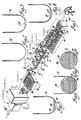
- Figure 1 is a pictorial view of a preferred apparatus for carrying out the fabrication and assembly of a catalyst substrate according to the present invention.
- Figures 2-7 are sequential views taken along the lines 2-2, 3-3, 4-4, 5-5, 6-6 and 7-7 respectively in Figure 1 illustrating sequential operations in the fabrication and assembly of the catalyst substrate.
- Referring to Figure 1, the catalyst substrate fabrication and assembly apparatus thereshown comprises a plurality of stations starting with Station No.1 which has a
coil reel 10 holding a strip ofstainless steel 12 that is used to form the shell of what may be referred to as a single seam version of the metal monolith substrate assembly disclosed in U.S. Patent 4,559,205 and which is hereby incorporated by reference. To this end, the stainless steel stock is pre-slit to the width required to produce the perimeter shell which will match the cross-sectional shape or outline desired of the foil layers and may be either circular as shown or oval or of some polygonal shape. In the description that follows, it will be seen that the widths of the foil are made equal to the various chordal dimensions of the circular substrate shape shown and thus vary in equal steps and it will be understood that the foil width dimensions will vary differently according to the cross-sectional substrate profile desired and not at all in the case of a square or rectangular shape. Thestrip stock 12 fromStation 1 is fed to a roll-formingStation 2 which, like in a conventional tube mill, comprises an edge conditioner 14,entry guide 16, a plurality of breakdown roller passes 18, and a plurality of cluster units 20 which all co-operate to form the stainless steel strip stock into a preliminary concave or U-shape as shown in Figure 2 that is necessary to generate the final closed form. - The U-shaped strip stock exiting from
Station 2 is delivered to aStation 3 which has a coil reel 22 of flat, oxidized stainless steel foil 24 that has been pre-slit to a width that is required for the first substrate layer. The foil 24 unwinds from the reel 22 and enters into a conventional corrugating roll-formingsubstation 26 which generates a corrugated pattern in the foil that is parallel to the direction of foil travel. As the thus producedcorrugated foil 25 exits the corrugating rollers, it is guided by a final roller 28 onto the bottom of the thus far formed U-shaped shell as seen in Figure 3 as it advances along the line toward thenext Station 4. - At
Station 4, there is a reel 29 holding another coil 30 of the oxidized stainless steel foil but which has been pre-slit to the width required for a second layer. This foil unwinds from the reel and is guided by opposed rollers 32 and afinal roller 33 onto the top of the first layer offoil 25 as seen in Figure 4. This foil may be flat as shown or herringbone-corrugated depending on the type of substrate desired. - From
Station 3, the partially formed shell now containing two layers of foil is passed ontoStation 5 and through to Station N. These stations are duplicates ofStations next layer 34 which is corrugated as seen in Figure 5) so as to build up the stack to the desired form. Station N is defined as the last station laying down thelast layer 35 of the foil stack which may be flat as shown in Figure 6. The unconstrained stack height of the substrate resulting from the addition of the Nth layer of foil is sufficient to furnish adequate compressive pressure when constrained in the finished substrate after the manner of that disclosed in the aforementioned U.S. Patent 4,559,205. - From the N Station, the partially formed shell now containing all the required layers of foil is advanced to Station N + 1. This station comprises clusters 36 and forming rollers 37 that complete roll-forming the shell to the desired shape, which in this case is round. This completely encloses the foil layers with a shell that constrains the foil layers and provides the compressive loading on the substrate disclosed in the aforementioned U.S. Patent 4,559,205.
- Thereafter, the thus closed tubular shell containing the layered foil is advanced onto Station N+2 which has a conventional high frequency AC or DC welding supply and welding electrodes that seam-weld a single tube seam completing a leak-
tight shell 38. - From the seam-welding station, the thus closed and welded
shell 38 containing the compressed foil layers is advanced onto Station N+3 which has a conventional flying cutoff system utilizing a shear. This station cuts the emerging metal honeycomb structuredshell 38 into prescribedlengths 38′ of, for example, 3 to 6 metre lengths (e.g. 10 to 20 foot lengths) which may be referred to as logs as it is intended that such be subsequently recut in a burrless manner into the proper monolith substrate lengths such as by laser cutting, high speed abrasive cutting, water jet cutting or possible double-action shear cutting. - After the logs are recut into the proper substrate lengths, subsequent conventional operations such as cleaning, coating and calcining are completed. Following these operations, two funnel-shaped parts may be welded to the ends of the shell to form an inlet and outlet to complete the catalytic converter assembly as disclosed in the aforementioned U.S. Patent 4,559,205. These funnel-shaped parts provide end support to the substrate and along with the compression of the substrate by the shell assure the structural integrity of the substrate as disclosed in the afore-mentioned U.S. Patent 4,559,205.
- The foregoing description of the preferred embodiment of the invention has been presented for purposes of illustration and description. It is not intended to be exhaustive or to limit the invention to the precise form disclosed. Obvious modifications or variations are possible in light of the above disclosure. The embodiment was chosen and described to provide the best illustration of the principles of the invention and its practical application to thereby enable one of ordinary skill in the art to utilize the invention in various embodiments and with various modifications as are suited to the particular use contemplated. All such modifications and variations are within the scope of the invention as determined by the appended claims when interpreted in accordance with the breadth to which they are fairly, legally and equitably entitled.
Claims (2)
Applications Claiming Priority (2)
| Application Number | Priority Date | Filing Date | Title |
|---|---|---|---|
| US121404 | 1980-02-14 | ||
| US07/121,404 US4782570A (en) | 1987-11-16 | 1987-11-16 | Fabrication and assembly of metal catalytic converter catalyst substrate |
Publications (2)
| Publication Number | Publication Date |
|---|---|
| EP0317075A1 true EP0317075A1 (en) | 1989-05-24 |
| EP0317075B1 EP0317075B1 (en) | 1991-05-22 |
Family
ID=22396495
Family Applications (1)
| Application Number | Title | Priority Date | Filing Date |
|---|---|---|---|
| EP88309493A Expired - Lifetime EP0317075B1 (en) | 1987-11-16 | 1988-10-11 | Fabrication and assembly of metal catalytic converter catalyst substrate |
Country Status (6)
| Country | Link |
|---|---|
| US (1) | US4782570A (en) |
| EP (1) | EP0317075B1 (en) |
| JP (1) | JPH01164443A (en) |
| KR (1) | KR910003262B1 (en) |
| DE (1) | DE3862924D1 (en) |
| MX (1) | MX169395B (en) |
Cited By (1)
| Publication number | Priority date | Publication date | Assignee | Title |
|---|---|---|---|---|
| CN102248368A (en) * | 2011-06-14 | 2011-11-23 | 天津华源盛电器控制设备有限公司 | KB section rolling forming method |
Families Citing this family (26)
| Publication number | Priority date | Publication date | Assignee | Title |
|---|---|---|---|---|
| DE3738537A1 (en) * | 1987-11-13 | 1989-06-01 | Sueddeutsche Kuehler Behr | METHOD AND DEVICE FOR PRODUCING A SUPPORT BODY FOR A CATALYTIC REACTOR |
| FR2656376B1 (en) * | 1989-12-22 | 1994-04-29 | Rosi Ets | EXHAUST, ESPECIALLY CATALYTIC, FOR BURNED GASES FROM INTERNAL COMBUSTION ENGINES. |
| US5094074A (en) * | 1990-02-23 | 1992-03-10 | Nissan Motor Co., Ltd. | Catalytic converter with metallic carrier and method for producing same |
| US5814164A (en) | 1994-11-09 | 1998-09-29 | American Scientific Materials Technologies L.P. | Thin-walled, monolithic iron oxide structures made from steels, and methods for manufacturing such structures |
| US6045628A (en) * | 1996-04-30 | 2000-04-04 | American Scientific Materials Technologies, L.P. | Thin-walled monolithic metal oxide structures made from metals, and methods for manufacturing such structures |
| EP0871536A1 (en) * | 1995-07-12 | 1998-10-21 | Engelhard Corporation | Structure for converter body |
| US5737839A (en) * | 1995-12-22 | 1998-04-14 | Engelhard Corporation | Assembly and method for making catalytic converter structures |
| WO1997023325A1 (en) * | 1995-12-22 | 1997-07-03 | W.R. Grace & Co. | Assembly and method for making catalytic converter structures |
| US5937516A (en) * | 1996-12-13 | 1999-08-17 | General Motors Corporation | Method for spin forming articles |
| US6405437B1 (en) | 1997-09-17 | 2002-06-18 | Arvinmeritor, Inc. | Apparatus and method for encasing an object in a case |
| DE19740966C2 (en) * | 1997-09-17 | 1999-09-09 | Emitec Emissionstechnologie | Method for producing a metallic carrier body and a metallic carrier body for an exhaust system of an internal combustion engine |
| CA2305725A1 (en) | 1997-10-07 | 1999-04-15 | Arvin Industries, Inc. | Exhaust processor end cap |
| US6125540A (en) * | 1998-02-17 | 2000-10-03 | Newcourt, Inc. | Continuous process for forming structure suitable for use as a core member |
| US6162403A (en) * | 1998-11-02 | 2000-12-19 | General Motors Corporation | Spin formed vacuum bottle catalytic converter |
| US6418909B2 (en) * | 1998-11-24 | 2002-07-16 | Robert Bosch Corporation | Low cost hydraulic damper element and method for producing the same |
| US6461562B1 (en) | 1999-02-17 | 2002-10-08 | American Scientific Materials Technologies, Lp | Methods of making sintered metal oxide articles |
| DE1200716T1 (en) * | 1999-07-13 | 2003-11-27 | Wimetal Sa | METHOD FOR PRODUCING CATALYSTS AND ARRANGEMENT FOR IMPLEMENTING THE METHOD |
| JP2003533413A (en) * | 2000-05-12 | 2003-11-11 | エイティーディー コーポレイション | Multi-compartment structure for insulation or other materials |
| US6506276B1 (en) | 2000-06-12 | 2003-01-14 | Newcourt, Inc. | Method for forming a cellular core member |
| US6938339B2 (en) * | 2000-12-19 | 2005-09-06 | Corning Incorporated | Method and apparatus for forming an inlet and outlet face of a catalyst support |
| US7497202B2 (en) * | 2004-10-15 | 2009-03-03 | Robert Bosch Gmbh | Hydraulic damper element |
| US20070294891A1 (en) * | 2006-06-23 | 2007-12-27 | Haimian Cai | Method of forming a catalytic converter from a radially deformed pre-form member |
| US7921881B2 (en) * | 2006-12-15 | 2011-04-12 | Millennium Industries Corporation | Fluid conduit assembly |
| WO2016160700A1 (en) * | 2015-03-30 | 2016-10-06 | Basf Corporation | Multifunctional coating system and coating module for application of catalytic washcoat and/or solution to a substrate and methods thereof |
| US10598068B2 (en) | 2015-12-21 | 2020-03-24 | Emissol, Llc | Catalytic converters having non-linear flow channels |
| DE102017205147B4 (en) * | 2017-03-27 | 2019-04-04 | Continental Automotive Gmbh | Process for producing a honeycomb body |
Citations (5)
| Publication number | Priority date | Publication date | Assignee | Title |
|---|---|---|---|---|
| GB836489A (en) * | 1958-03-03 | 1960-06-01 | Solar Aircraft Co | Apparatus and system for producing honeycomb core |
| EP0151229A1 (en) * | 1983-11-19 | 1985-08-14 | Süddeutsche Kühlerfabrik Julius Fr. Behr GmbH & Co. KG | Matrix for catalytic reactor |
| US4576800A (en) * | 1984-09-13 | 1986-03-18 | Camet, Inc. | Catalytic converter for an automobile |
| DE3622115C1 (en) * | 1986-07-02 | 1987-09-03 | Daimler Benz Ag | Metallic carrier for catalytic converters of Otto engines |
| EP0238831A1 (en) * | 1986-02-18 | 1987-09-30 | W.R. Grace & Co.-Conn. | Process for making a catalyst core |
Family Cites Families (9)
| Publication number | Priority date | Publication date | Assignee | Title |
|---|---|---|---|---|
| US4020539A (en) * | 1973-03-19 | 1977-05-03 | Chrysler Corporation | Catalytic reactor for automobile |
| DE2400443A1 (en) * | 1974-01-05 | 1975-07-10 | Erhardt Bischoff Fabrik Fuer K | Catalytic exhaust gas cleaner - has catalytic material spaced from cylindrical housing by corrugated steel packing |
| US4335078A (en) * | 1977-09-13 | 1982-06-15 | Nissan Motor Company, Limited | Catalytic reactor for automotive exhaust line |
| DE2924592C2 (en) * | 1979-06-19 | 1983-05-26 | Süddeutsche Kühlerfabrik Julius Fr. Behr GmbH & Co KG, 7000 Stuttgart | Method for producing a carrier matrix for a catalytic reactor for exhaust gas purification in internal combustion engines of motor vehicles |
| US4347219A (en) * | 1979-12-29 | 1982-08-31 | Honda Giken Kogyo Kabushiki Kaisha | Catalytic converter for exhaust-gas cleaning use and method of assembling same |
| DE3527111A1 (en) * | 1985-07-29 | 1987-01-29 | Interatom | METAL, WINDED EXHAUST GAS CATALYST SUPPORT BODY WITH A GEOMETRICALLY COMPLEX FORM OF THE CROSS-SECTION, AND METHOD, DEVICE AND ROLLING FOR ITS PRODUCTION |
| US4598063A (en) * | 1985-08-09 | 1986-07-01 | Retallick William B | Spiral catalyst support and method of making it |
| US4667386A (en) * | 1985-08-23 | 1987-05-26 | Honda Giken Kogyo Kabushiki Kaisha | Method and apparatus for assembling an insert assembly for a catalytic converter |
| FI74523C (en) * | 1986-04-29 | 1988-02-08 | Kemira Oy | Preparation and fortification process of a catalytic cell intended for purification of exhaust gas. |
-
1987
- 1987-11-16 US US07/121,404 patent/US4782570A/en not_active Expired - Fee Related
-
1988
- 1988-10-11 EP EP88309493A patent/EP0317075B1/en not_active Expired - Lifetime
- 1988-10-11 DE DE8888309493T patent/DE3862924D1/en not_active Expired - Fee Related
- 1988-11-14 KR KR1019880014960A patent/KR910003262B1/en not_active IP Right Cessation
- 1988-11-15 MX MX026507A patent/MX169395B/en unknown
- 1988-11-16 JP JP63287874A patent/JPH01164443A/en active Granted
Patent Citations (5)
| Publication number | Priority date | Publication date | Assignee | Title |
|---|---|---|---|---|
| GB836489A (en) * | 1958-03-03 | 1960-06-01 | Solar Aircraft Co | Apparatus and system for producing honeycomb core |
| EP0151229A1 (en) * | 1983-11-19 | 1985-08-14 | Süddeutsche Kühlerfabrik Julius Fr. Behr GmbH & Co. KG | Matrix for catalytic reactor |
| US4576800A (en) * | 1984-09-13 | 1986-03-18 | Camet, Inc. | Catalytic converter for an automobile |
| EP0238831A1 (en) * | 1986-02-18 | 1987-09-30 | W.R. Grace & Co.-Conn. | Process for making a catalyst core |
| DE3622115C1 (en) * | 1986-07-02 | 1987-09-03 | Daimler Benz Ag | Metallic carrier for catalytic converters of Otto engines |
Cited By (1)
| Publication number | Priority date | Publication date | Assignee | Title |
|---|---|---|---|---|
| CN102248368A (en) * | 2011-06-14 | 2011-11-23 | 天津华源盛电器控制设备有限公司 | KB section rolling forming method |
Also Published As
| Publication number | Publication date |
|---|---|
| US4782570A (en) | 1988-11-08 |
| MX169395B (en) | 1993-06-30 |
| KR910003262B1 (en) | 1991-05-25 |
| DE3862924D1 (en) | 1991-06-27 |
| JPH0466613B2 (en) | 1992-10-23 |
| JPH01164443A (en) | 1989-06-28 |
| KR890008431A (en) | 1989-07-10 |
| EP0317075B1 (en) | 1991-05-22 |
Similar Documents
| Publication | Publication Date | Title |
|---|---|---|
| EP0317075B1 (en) | Fabrication and assembly of metal catalytic converter catalyst substrate | |
| US5983692A (en) | Process and apparatuses for producing a metal sheet with a corrugation configuration and a microstructure disposed transversely with respect thereto | |
| EP0238831B1 (en) | Process for making a catalyst core | |
| CA2557277C (en) | A production line and a method of forming profiles | |
| RU2440206C2 (en) | Boring holes in foil and cellular elements made thereof to process waste gases (versions) | |
| EP1590557B1 (en) | Method and tool for producing structured sheet metal layers, and catalyst support | |
| CA2604626A1 (en) | A production line and a method of shaping profiles | |
| RU2279557C2 (en) | Cellular member, method and device for its manufacture, and catalytic converter carrier | |
| CN1193924A (en) | Layered sheet metal with rolled-on solder and process for manufacturing a honeycombed body therefrom | |
| EP2731739A1 (en) | Method and device for producing tailored sheet-metal strips | |
| US7578217B2 (en) | Manufacturing razor blades | |
| JPH01501853A (en) | Manufacturing method of lightweight shapes | |
| DE60107011T2 (en) | Catalyst support for an exhaust gas purification system and method for its production | |
| EP0398479A1 (en) | Catalytic converter substrate and assembly | |
| US4603807A (en) | Mill for roll forming a fluted tube | |
| EP1231366A1 (en) | Exhaust casing part for a motor vehicle, particularly for an exhaust silencer or an exhaust gas catalyst | |
| US6286353B1 (en) | Process for producing at least one structured metal sheet, process for producing a laminated metal sheet pack and apparatus for producing structured metal sheets | |
| JPH0463738B2 (en) | ||
| US2641830A (en) | Method of making corrugated tubes | |
| US4767740A (en) | Metallic support for exhaust gas catalysts of Otto-engines and method for making the support | |
| DE10015212A1 (en) | Metallic carrier production for catalytic converter, involves winding metal sheets in cylinder form so that end portion of protrusion provided on each sheet joins with surface of adjoining sheet | |
| DE4018704C2 (en) | Process for producing wound and / or layered metallic catalyst supports | |
| US5094997A (en) | Porous support | |
| WO2004011170A1 (en) | Method and device for producing a profiled sheet metal material, sheet metal material profiled in a corrugated manner, metallic composite body and catalyst | |
| US7309399B2 (en) | System and method for manufacturing filling strips configured for use with a corrugated member |
Legal Events
| Date | Code | Title | Description |
|---|---|---|---|
| PUAI | Public reference made under article 153(3) epc to a published international application that has entered the european phase |
Free format text: ORIGINAL CODE: 0009012 |
|
| AK | Designated contracting states |
Kind code of ref document: A1 Designated state(s): DE FR GB IT |
|
| 17P | Request for examination filed |
Effective date: 19890623 |
|
| 17Q | First examination report despatched |
Effective date: 19900807 |
|
| ITF | It: translation for a ep patent filed |
Owner name: BARZANO' E ZANARDO ROMA S.P.A. |
|
| GRAA | (expected) grant |
Free format text: ORIGINAL CODE: 0009210 |
|
| AK | Designated contracting states |
Kind code of ref document: B1 Designated state(s): DE FR GB IT |
|
| REF | Corresponds to: |
Ref document number: 3862924 Country of ref document: DE Date of ref document: 19910627 |
|
| ET | Fr: translation filed | ||
| PLBE | No opposition filed within time limit |
Free format text: ORIGINAL CODE: 0009261 |
|
| STAA | Information on the status of an ep patent application or granted ep patent |
Free format text: STATUS: NO OPPOSITION FILED WITHIN TIME LIMIT |
|
| 26N | No opposition filed | ||
| PGFP | Annual fee paid to national office [announced via postgrant information from national office to epo] |
Ref country code: GB Payment date: 19941010 Year of fee payment: 7 |
|
| PGFP | Annual fee paid to national office [announced via postgrant information from national office to epo] |
Ref country code: FR Payment date: 19941028 Year of fee payment: 7 |
|
| PGFP | Annual fee paid to national office [announced via postgrant information from national office to epo] |
Ref country code: DE Payment date: 19941129 Year of fee payment: 7 |
|
| PG25 | Lapsed in a contracting state [announced via postgrant information from national office to epo] |
Ref country code: GB Effective date: 19951011 |
|
| GBPC | Gb: european patent ceased through non-payment of renewal fee |
Effective date: 19951011 |
|
| PG25 | Lapsed in a contracting state [announced via postgrant information from national office to epo] |
Ref country code: FR Effective date: 19960628 |
|
| PG25 | Lapsed in a contracting state [announced via postgrant information from national office to epo] |
Ref country code: DE Effective date: 19960702 |
|
| REG | Reference to a national code |
Ref country code: FR Ref legal event code: ST |
|
| PG25 | Lapsed in a contracting state [announced via postgrant information from national office to epo] |
Ref country code: IT Free format text: LAPSE BECAUSE OF NON-PAYMENT OF DUE FEES Effective date: 20051011 |