EP0316519A1 - Method for measuring and correcting the ram adjustment of high-speed punching presses, and circuit for carrying out the method - Google Patents
Method for measuring and correcting the ram adjustment of high-speed punching presses, and circuit for carrying out the method Download PDFInfo
- Publication number
- EP0316519A1 EP0316519A1 EP19880113357 EP88113357A EP0316519A1 EP 0316519 A1 EP0316519 A1 EP 0316519A1 EP 19880113357 EP19880113357 EP 19880113357 EP 88113357 A EP88113357 A EP 88113357A EP 0316519 A1 EP0316519 A1 EP 0316519A1
- Authority
- EP
- European Patent Office
- Prior art keywords
- measured
- ram
- plunger
- amplitude
- circuit
- Prior art date
- Legal status (The legal status is an assumption and is not a legal conclusion. Google has not performed a legal analysis and makes no representation as to the accuracy of the status listed.)
- Granted
Links
- 238000004080 punching Methods 0.000 title claims abstract description 4
- 238000000034 method Methods 0.000 title claims description 20
- 230000006870 function Effects 0.000 claims abstract description 19
- 238000007654 immersion Methods 0.000 claims abstract description 14
- 238000005520 cutting process Methods 0.000 claims abstract description 4
- 238000005452 bending Methods 0.000 claims abstract description 3
- 239000011265 semifinished product Substances 0.000 claims abstract description 3
- 230000006698 induction Effects 0.000 claims abstract 4
- 238000005259 measurement Methods 0.000 claims description 14
- 238000012937 correction Methods 0.000 claims description 12
- 238000006073 displacement reaction Methods 0.000 abstract 1
- 230000015654 memory Effects 0.000 description 16
- 238000011156 evaluation Methods 0.000 description 6
- 230000001965 increasing effect Effects 0.000 description 6
- 239000002184 metal Substances 0.000 description 4
- 238000001514 detection method Methods 0.000 description 2
- 238000010586 diagram Methods 0.000 description 2
- 230000001939 inductive effect Effects 0.000 description 2
- 230000009471 action Effects 0.000 description 1
- 230000008901 benefit Effects 0.000 description 1
- 230000015572 biosynthetic process Effects 0.000 description 1
- 230000008859 change Effects 0.000 description 1
- 238000006243 chemical reaction Methods 0.000 description 1
- 230000008878 coupling Effects 0.000 description 1
- 238000010168 coupling process Methods 0.000 description 1
- 238000005859 coupling reaction Methods 0.000 description 1
- 238000011161 development Methods 0.000 description 1
- 230000018109 developmental process Effects 0.000 description 1
- 238000004049 embossing Methods 0.000 description 1
- 230000007613 environmental effect Effects 0.000 description 1
- 238000009434 installation Methods 0.000 description 1
- 230000007257 malfunction Effects 0.000 description 1
- 238000000691 measurement method Methods 0.000 description 1
- 230000008569 process Effects 0.000 description 1
- 238000012545 processing Methods 0.000 description 1
- 230000009467 reduction Effects 0.000 description 1
- 238000009420 retrofitting Methods 0.000 description 1
- 230000003068 static effect Effects 0.000 description 1
- 238000012360 testing method Methods 0.000 description 1
- 238000009423 ventilation Methods 0.000 description 1
Images


Classifications
-
- B—PERFORMING OPERATIONS; TRANSPORTING
- B30—PRESSES
- B30B—PRESSES IN GENERAL
- B30B15/00—Details of, or accessories for, presses; Auxiliary measures in connection with pressing
- B30B15/0029—Details of, or accessories for, presses; Auxiliary measures in connection with pressing means for adjusting the space between the press slide and the press table, i.e. the shut height
- B30B15/0041—Control arrangements therefor
-
- Y—GENERAL TAGGING OF NEW TECHNOLOGICAL DEVELOPMENTS; GENERAL TAGGING OF CROSS-SECTIONAL TECHNOLOGIES SPANNING OVER SEVERAL SECTIONS OF THE IPC; TECHNICAL SUBJECTS COVERED BY FORMER USPC CROSS-REFERENCE ART COLLECTIONS [XRACs] AND DIGESTS
- Y10—TECHNICAL SUBJECTS COVERED BY FORMER USPC
- Y10T—TECHNICAL SUBJECTS COVERED BY FORMER US CLASSIFICATION
- Y10T83/00—Cutting
- Y10T83/141—With means to monitor and control operation [e.g., self-regulating means]
Definitions
- the invention relates to a method according to the preamble of claim 1 and to a circuit for performing such a method.
- a circuit arrangement by means of which the actual value immersion depth of such a tappet is determined by inductive measurement and with which a corresponding actual / target value comparison is then possible in order to carry out the required correction is known from DE-PS 27 31 084.
- the tappet adjustment at stroke rates of over 600 strokes per minute is corrected by means of a motor which acts via a gear train with a high reduction ratio on a pin bearing adjusting element, by means of which the tappet opposes its drive member is adjustable, wherein the immersion depth can be changed, that is, corrected in the desired manner.
- this known circuit can also be used to make a correction via a program stored in a memory, and depending on the number of strokes corresponding to this program, monostable flip-flops are supplied with control signals which in turn control the correction motor according to the signal information.
- Another known circuit arrangement for an actuator of a plunger adjustment uses at least one limit switch for detecting the immersion depth, which is adjustably attached to the press frame in the action of the plunger and whose signal output is connected to the set input of a first flip-flop, the signal output is in turn coupled back to a reset input of a further flip-flop by means of a branch line via a switching stage which determines the size of an adjustment step, a set input of a further flip-flop having a switch activated when the cutting press is interrupted and a reset input of the latter flip-flop is connected to a further switch which is activated when the plunger has reached a lowermost position relative to its drive element, which it must not fall short of depending on the tool.
- the two known circuit arrangements have the advantage that the ram adjustment is possible during the operation of the press, on the other hand however, the main disadvantage that these are very complex circuit arrangements, with a correspondingly high outlay on costs for both the hardware and the software side.
- the present invention uses this known prior art and it is based on the object of providing a method and a circuit arrangement of the generic type and designing such that the plunger immersion depth measurements and the corrections which can be carried out with them are carried out with the least possible susceptibility to malfunction and with a manageably low outlay on equipment becomes possible.
- the present task solution advantageously enables the increasingly precise tools of the type of interest here to be able to adapt to the higher quality requirements, even with an increased stroke rate of the presses.
- Special parts in the electrical and electronics industry can therefore be manufactured with very tight tolerances regardless of the stroke speed, specifically for stroke speeds that can be, for example, 2000 strokes per minute.
- the measuring system used is robust enough to withstand the harsh environmental conditions prevailing for such press operations without that this affects its high measuring accuracy.
- the implementation of the method with the associated circuit arrangement is simple, in particular also for the operator of the press, whereby restrictions on the tool installation space, in contrast to the prior art, are practically completely eliminated. It is also not necessary in the present solution to the problem to have to make readjustments, or to have to carry out special mechanical adjustments and thus time-consuming work on the press itself.
- a tape applied to a metal band and magnetized at certain high-precision intervals serves as a measuring ruler, while the sensor head is characterized by four coils that are fed with a carrier frequency, the voltage induced in the coils being fed to the function evaluation by the relative movement between the metal band and the sensor . Because the coil arrangement in the detector head supplies two sine voltages offset by ninety degrees, a directional detection of the relative movement between the metal strip and the sensor head and thus between the ram movement and the press frame can be predefined in a simple manner.
- the evaluation of the inductive and thus non-contact measurement method is particularly simple in that first a rough path measurement is carried out by generating counting pulses at the zero crossings of the sine / cosine functions and that the amplitude value is stored at the reversal points for the two functions and this for the exact ones Measurement is evaluated.
- the Relativbe serve movement between the sensor head and permanent magnetic head equally as for the evaluation of their automatic operation, tei the possible existing deviation is first measured and displayed and after measurement of the deviation the machine is stopped, if the measurement proves a correction necessary, which in turn is then carried out automatically.
- Block 3 takes the magnetic ruler 1, which is characterized by alternating magnetic poles (cf. also FIG. 3) that alternate every two millimeters in length and are applied to a suitable metal strip.
- the block 3 is firmly attached to the machine frame of the press, for which the receiving channel is used. It is also possible to fix the block 3 not on the static press part but on the moving tool part.
- the sensor head 4 consists essentially of a detector 2, in which four coils are accommodated, which are acted upon with a suitable carrier frequency.
- the relative movement between the fixed tool half of the press and the moving tool half, i.e. the plunger, corresponds to the relative movement between the magnetic ruler 1 and the sensor head 4, the detector 2 being moved close to the magnetic ruler and parallel to it in the double arrow direction shown.
- the contactless length measurement of the distance thus traveled along the north-south pole arrangement which changes every two millimeters at a distance between the magnetic ruler 1 and detector 2 of 0.1 to a maximum of 0.5 mm, influences the amplitude of the carrier frequency and thus modulates the carrier frequency in the Coils of the detector head 4 AC voltages, the respective course of which corresponds to sine functions, but which are offset by 90 degrees to one another, since the distances between the individual coils are matched to the distances between the alternating north-south pole arrangements in the ruler.
- the Voltage profiles picked up by the detector 2 in the scanning head 4 are fed via a line 6 to the plunger immersion depth measurement unit 7 and processed there in a manner to be described later.
- a coupling piece 8 makes it possible to separate the sensor head, which in the exemplary embodiment is movably attached to the ram, from the processing and display unit 7 and to install it independently at a suitable location within the press or next to it.
- the front panel of the device 7 contains a text display for the operator, a numerical display for the measured values obtained, as well as control buttons for different functions and a key selector switch for the possible operating modes.
- the possible operating modes consist in converting the press, in which parts of the device are set to a certain stroke and thus to a defined ram position, which is about the same as the respective tool change.
- Another mode of operation under the term “automatic” means that the device automatically orients itself to the new plunger position after the conversion has been carried out, it being possible for the device to measure a certain deviation, and the press then stops first if the deviation exceeds a tolerance limit - or falls below and then makes the necessary correction itself.
- another operating mode "bypass / stroke"
- the device outputs are inactive; The current stroke is displayed, whereby this operating mode lies outside the actual operation of the device.
- ventilation a mode of operation called “ventilation” is provided, which is used to travel a path for the ram in the upward direction that was defined during commissioning, that is to say to separate the two tool halves for test purposes.
- the contactless, sliding movement of the scanning head 4 along the magnetic ruler 1 initially leads to a rough path measurement by generating counting pulses at the zero crossings of the sine curve in that one pulse results per millimeter of path.
- the amplitude values are recorded or stored at the reversal points of the voltage curve, and the counting impulses thus given are used to roughly determine the path of a specific stroke quantity.
- the anologic sinus amplitude measured at the reversal point of the movement of the plunger see also FIG.
- the plunger immersion depth is fundamentally continuously or variably adjustable, the respective plunger deviation being measured with increasing stroke frequency and the increase in immersion depth being measured by this increasing frequency while the press is running and this is then stopped when a set tolerance limit is either reached is exceeded or undershot upwards or downwards.
- the deviation that has occurred is corrected during the downtime of the press, for which purpose the press is switched from the "continuous operation" mode to "setup", that is to say discontinuous operation. After the correction that has become necessary is taken into account, the press then operates again until the set tolerance range is left again or until the press may need to be set up again.
- the use of the scanning head 4 in conjunction with the magnetic ruler 1 in the embodiment shown in FIG. 1 is particularly advantageous in so far as the corrections which can be predetermined thereby are independent of the actual tool, that is to say the plunger and the like. as well as the fixed press half, ie that wear of the individual tool parts does not impair the measuring process, as is the case, for example, with the ram correction using the known limit switches.
- the sine / cosine curve in the coils within the sensor head 4, which are offset by one millimeter from one another in the exemplary embodiment, is shown in FIG. 2 at the reversal point of the up-down movement of a plunger.
- the reversal point For the measurement of the reversal point, it is ultimately of no interest how many sine or cosine periods are traversed to the reversal point of the ram; the only thing of interest for the measurement of the reversal point is the last maximum of the sine or cosine function before the reversal point or the amplitude of the functions directly at the reversal point.
- One of these values is used for the evaluation as a reference voltage and the last one in each case voltage value occurring at the reversal point as a measured value. As can be seen from FIG.
- the reversal point practically represents a mirror plane for both the sine and the cosine function, which exactly defines the measured value and the reference value for the evaluation electronics and, in the exemplary embodiment, a deviation from the desired immersion depth with an accuracy of up to 1 / 100 millimeters.
- Fig. 3 shows a block circuit diagram of a circuit which enables the aforementioned functions.
- the scanning head 4 which is guided past the magnetic ruler at a distance, outputs, via the detector 2 consisting of four coils, which are fed via an oscillator 10 with a suitable carrier frequency, the signals which are modulated by the relative movement between the detector 2 and the magnetic ruler 1 in the form of the aforementioned sine waves. respectively.
- Cosine signals each directly to an associated low-pass filter 12, 13 or via the digital analog converter 11, 14 to the other low-pass filter 13, 12.
- Each of the low-pass filters 12, 13 is on the output side with the two peak value memories 15, 17 and 21, 22, one Rectifiers 19 and 43, respectively, and a converter 20, 24 are connected in the manner given in the functional representation.
- An electronic relay 25 switches the analog output signal information of the modules 19 and 23 to digital commands and leads these digital signals alternately to a peak value memory 28, which is followed by an analog measured value memory 29, corresponding to the analog measured value memories 16, 18, 26 and 27 are connected to the outputs of the peak value memories 15, 17, 21 and 22.
- the demodulated associated direct voltage components which are superimposed on the alternating voltage components, can be used by measuring the positive and negative peak values and digitizing these measured values for a computer-controlled correction.
- the integrated switching logic 30, which bwz with the converters 20.
- the outputs of the analog measured value memories 16, 18, 26, 27 and 29 are at the inputs of a multiplexer 31, the output information of which is amplified by an impedance converter 22 and can be fed to the memory logic 34 via the analog digital converter 33.
- the multiplexer 31 which can be switched by the computer and whose outputs feed an analog-digital converter as described above, the computer logic thus has access to each individual peak value which is supplied via the individual peak value memories.
- Half the difference between the peak values corresponds to the DC voltage offset, which is output with the correct sign at the respective digital / analog converter and subtracted at the signal input.
- the digital-analog converter signal (14, 11) on the output side passes through the low-pass filters 13, 12 in order to suppress the demodulated carrier frequency components (sine / cosine).
- the rectified signals are output in the manner described above from the rectifiers 19, 23 to the changeover switch 25, which, controlled by the logic circuit 30, switches through the signal which is clearly marked with the last maximum at the point of reversal, to the downstream peak value memory, while at the same time via the logic circuit 30, according to the reversal of direction indicated at the point of reversal, the voltage maximum is stored in the associated measured value memory.
- the distance in the exemplary embodiment is interpolated within a millimeter to within a hundredth of a millimeter.
- the measurement of the values added to one millimeter in each case is carried out by the computer 34 by enumerating the zero crossings of the sine and cosine signals.
- the zero crossings are processed via the logic circuit in the memory 34.
- the logic memory 34 is also connected to the display and operating part 35 and, of course, the inputs and outputs 36.
Abstract
Description
Die Erfindung bezieht sich auf ein Verfahren gemäß Oberbegriff des Anspruchs 1 und auf eine Schaltung zur Durchführung eines solchen Verfahrens.The invention relates to a method according to the preamble of
Es ist bei schnellaufenden Hubpressen bekannt, daß die Eintauchtiefe des Oberwerkzeuges in ein zugehöriges Unterwerkzeug mit zunehmender Arbeitsgeschwindigkeit zunimmt, wodurch sich die an die Presse gestellten Toleranzanforderungen sowohl für Schneide- oder Stanzvorgänge, als auch für Biege- und Prägearbeiten erheblich verschieben und negativ beeinflußt werden. Aber nicht nur die zu fertigenden Halbzeuge oder dergleichen leiden unter der Stößelverstellung, auch die Werkzeuge unterliegen hierdurch einem erhöhten Verschleiß, wodurch sich häufige Stillstandzeiten und erhöhte Werkzeugkosten nicht vermeiden lassen.It is known in high-speed lifting presses that the depth of immersion of the upper tool in an associated lower tool increases with increasing working speed, as a result of which the tolerance requirements placed on the press for cutting and punching operations, as well as for bending and embossing work, are significantly shifted and negatively influenced. But not only the semi-finished products or the like to be produced suffer from the ram adjustment, the tools are also subject to increased wear as a result of which frequent downtimes and increased tool costs cannot be avoided.
Eine Schaltungsanordnung mittels der die Ist-Wert-Eintauchtiefe eines solchen Stößels durch induktive Messung ermittelt wird und mit der dann ein entsprechender Ist-Sollwertvergleich möglich ist, um die erforderliche Korrektur vorzunehmen, ist aus der DE-PS 27 31 084 bekannt. Dort wird die Stößelverstellung bei Hubzahlen von über 600 Hüben pro Minute mittels eines Motors korrigiert, der über einen Getriebezug mit hoher Untersetzung auf ein Hublager-Einstellglied wirkt, durch das der Stößel gegenüber seinem Antriebsorgan verstellbar ist, wobei die Eintauchtiefe geändert, das heißt, in der gewünschten Weise korrigiert werden kann. Anstelle der laufenden Ist-Wertmessung der Eintauchtiefe kann bei dieser bekannten Schaltung auch eine Korrektur über ein in einem Speicher abgespeichertes Programm vorgenommen werden, wobei in Abhängikeit von der Hubzahl entsprechend diesem Programm monostabilen Kippstufen Stellsignale zugeführt werden, die ihrerseits den Korrekturmotor entsprechend den Signalinformationen ansteuern.A circuit arrangement by means of which the actual value immersion depth of such a tappet is determined by inductive measurement and with which a corresponding actual / target value comparison is then possible in order to carry out the required correction is known from DE-PS 27 31 084. There, the tappet adjustment at stroke rates of over 600 strokes per minute is corrected by means of a motor which acts via a gear train with a high reduction ratio on a pin bearing adjusting element, by means of which the tappet opposes its drive member is adjustable, wherein the immersion depth can be changed, that is, corrected in the desired manner. Instead of the current actual value measurement of the immersion depth, this known circuit can also be used to make a correction via a program stored in a memory, and depending on the number of strokes corresponding to this program, monostable flip-flops are supplied with control signals which in turn control the correction motor according to the signal information.
Eine andere bekannte Schaltungsanordnung für einen Stellantrieb einer Stößelverstellung (DE-PS 2833829) benutzt zur Erfassung der Eintauchtiefe mindestens einen Endschalter, der im Wirkungsweg des Stößels einstellbar am Pressengestell angebracht ist und dessen Signalausgang mit dem Setzeingang eines ersten Flip-Flops verbunden ist, dessen Signalausgang wiederum mittels einer Abzweigleitung über eine die Größe eines Verstellschrittes bestimmenden Schaltstufe auf einen Rücksetzeingang eines weiteren Flip-Flops rückgekoppelt ist, wobei ein Setzeingang eines noch weiteren Flip-Flops mit einem bei Unterbrechung des Betriebes der Schnittpresse aktivierten Schalter und ein Rücksetzeingang des letzgenannten Flip-Flops mit einem weiteren Schalter verbunden ist, der aktiviert wird, wenn der Stößel eine unterste Lage gegenüber seinem Antriebsorgan erreicht hat, die er werkzeugbezogen nicht unterschreiten darf.Another known circuit arrangement for an actuator of a plunger adjustment (DE-PS 2833829) uses at least one limit switch for detecting the immersion depth, which is adjustably attached to the press frame in the action of the plunger and whose signal output is connected to the set input of a first flip-flop, the signal output is in turn coupled back to a reset input of a further flip-flop by means of a branch line via a switching stage which determines the size of an adjustment step, a set input of a further flip-flop having a switch activated when the cutting press is interrupted and a reset input of the latter flip-flop is connected to a further switch which is activated when the plunger has reached a lowermost position relative to its drive element, which it must not fall short of depending on the tool.
Die beiden bekannten Schaltungsanordnungen haben den Vorteil, daß die Stößelverstellung während des Betriebes der Presse möglich ist, andererseits jedoch den wesentlichen Nachteil, daß es sich hierbei um sehr aufwendige Schaltungsanordnungen handelt, mit entsprechend hohem Aufwand an Kosten sowohl für die Hardwareals auch die Softwareseite.The two known circuit arrangements have the advantage that the ram adjustment is possible during the operation of the press, on the other hand however, the main disadvantage that these are very complex circuit arrangements, with a correspondingly high outlay on costs for both the hardware and the software side.
Die vorliegende Erfindung setzt bei diesem bekannten Stand der Technik ein und es liegt ihr die Aufgabe zugrunde, ein Verfahren und eine Schaltungsanordnung der gattungsgemäßen Art zuschaffen und so auszubilden, daß die Stößeleintauchtiefenmessungen und die hiermit durchführbaren Korrekturen bei geringstmöglicher Störanfälligkeit und mit einem überschaubar geringem apparativem Aufwand möglich wird.The present invention uses this known prior art and it is based on the object of providing a method and a circuit arrangement of the generic type and designing such that the plunger immersion depth measurements and the corrections which can be carried out with them are carried out with the least possible susceptibility to malfunction and with a manageably low outlay on equipment becomes possible.
Die Lösung dieser Aufgabe wird erfindungsgemäß durch die im Kennzeichen des Anspruchs 1 angegebenen Merkmale erreicht.This object is achieved according to the invention by the features specified in the characterizing part of
Vorteilhafte Weiterbildungen und Ausgestaltungen isnbesondere auch für die Ausbildung der Schaltung zur Durchführung des Verfahrens ergeben sich aus den Unteransprüchen.Advantageous further developments and refinements, in particular also for the formation of the circuit for carrying out the method, result from the subclaims.
Die vorliegende Aufgabenlösung ermöglicht es in vorteilhafter Weise die immer präziser arbeitenden Werkzeuge der hier interessierenden Art, den höheren Qualitätsanforderungen anpassen zu können und zwar auch bei noch gesteigerter Hubzahl der Pressen. Spezialteile der Elektro- und Elektronikindustrie lassen sich somit mit sehr engen Toleranzen hubgeschwindigkeitsunabhängig fertigen, und zwar für Hubgeschwindigkeiten die z.B. 2000 Hübe pro Minute betragen können. Das verwendete Meßsystem ist robust genug um den rauhen, für derartige Pressenbetriebe gegebenen Umgebungsbedingungen standzuhalten, ohne daß hierdurch seine hohe Meßgenauigkeit beinträchtigt wird. Die Durchführung des Verfahrens mit der zugehörigen Schaltungsanordnurg ist einfach, insbesondere auch für die Bedienungsperson der Presse, wobei Beschränkungen des Werkzeugeinbauraumes, im Gegensatz zum Stand der Technik praktisch vollkommen entfallen. Auch ist es bei der vorliegenden erfindungsgemäßen Aufgabenlösung nicht erforderlich Nachjustierungen vornehmen zu müssen, oder besondere mechanische Anpassungen und damit zeitraubende Arbeiten an der Presse selbst ausführen zu müssen.The present task solution advantageously enables the increasingly precise tools of the type of interest here to be able to adapt to the higher quality requirements, even with an increased stroke rate of the presses. Special parts in the electrical and electronics industry can therefore be manufactured with very tight tolerances regardless of the stroke speed, specifically for stroke speeds that can be, for example, 2000 strokes per minute. The measuring system used is robust enough to withstand the harsh environmental conditions prevailing for such press operations without that this affects its high measuring accuracy. The implementation of the method with the associated circuit arrangement is simple, in particular also for the operator of the press, whereby restrictions on the tool installation space, in contrast to the prior art, are practically completely eliminated. It is also not necessary in the present solution to the problem to have to make readjustments, or to have to carry out special mechanical adjustments and thus time-consuming work on the press itself.
Ein auf ein Metallband aufgebrachtes und in bestimmten hochgenauen Abständen magnetisiertes Band dient als Meßlineal, während der Sensorkopf sich durch vier Spulen kennzeichnet, die mit einer Trägerfrequenz gespeist werden, wobei durch die Relativbewegung zwischen Metallband und Sensor die in den Spulen induzierte Spannung der Funktionsauswertung zugeführt wird. Dadurch, daß die Spulenanordnung im Detektorkopf zwei um neunzig Grad versetzte Sinusspannungen liefert, läßt sich auf einfache Weise eine Richtungserkennung der Relativbewegung zwischen Metallband und Sensorkopf und damit zwischen Stößelbewegung und Pressengestell vorgeben. Besonders einfach ist die Auswertung der induktiven und damit berührungslosen Meßmethode dadurch, daß zunächst eine grobe Wegmessung durch Erzeugung von Zählimpulsen an den Nulldurchgängen der Sinus-/Cosinusfunktionen erfolgt und daß eine Speicherung des Amplitudenwertes an den Umkehrpunkten für die beiden Funktionen vorgenommen und diese für die exakte Messung ausgewertet wird.A tape applied to a metal band and magnetized at certain high-precision intervals serves as a measuring ruler, while the sensor head is characterized by four coils that are fed with a carrier frequency, the voltage induced in the coils being fed to the function evaluation by the relative movement between the metal band and the sensor . Because the coil arrangement in the detector head supplies two sine voltages offset by ninety degrees, a directional detection of the relative movement between the metal strip and the sensor head and thus between the ram movement and the press frame can be predefined in a simple manner. The evaluation of the inductive and thus non-contact measurement method is particularly simple in that first a rough path measurement is carried out by generating counting pulses at the zero crossings of the sine / cosine functions and that the amplitude value is stored at the reversal points for the two functions and this for the exact ones Measurement is evaluated.
Für die Umrüstung einer Presse kann die Relativbe wegung zwischen Sensorkopf und Permanentmagnetkopf gleichermaßen dienen wie für die Auswertung ihres automatischen Betriebes, tei dem zunächst die gegebenenfalls vorliegende Abweichung gemessen und angezeigt wird und nach erfolgter Messung der Abweichung die Maschine angehalten wird, falls sich durch die Messung eine Korrektur für erforderlich erweist, die ihrerseits dann automatisch durchgeführt wird.For retrofitting a press, the Relativbe serve movement between the sensor head and permanent magnetic head equally as for the evaluation of their automatic operation, tei the possible existing deviation is first measured and displayed and after measurement of the deviation the machine is stopped, if the measurement proves a correction necessary, which in turn is then carried out automatically.
Anhand der beiliegenden Zeichnungen soll die vorliegende Verfahrensweise näher beschrieben werden, wobei diese auch eine vorteilhafte Schaltungsanordnung zur Druchführung des vorliegenden Verfahrens beinhaltet.The present procedure is to be described in more detail with reference to the accompanying drawings, which also include an advantageous circuit arrangement for carrying out the present method.
Es zeigen:
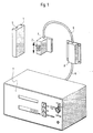
- Fig. 1 Einzelne Teile der Vorrichtung zur Durchführung des Verfahrens in perspektivischer Wiedergabe,
- Fig. 2 eine Funktionsdarstellung der am Umkehrpunkt des Stößels gemessenen Amplituden zur Verdeutlichung des vorliegenden Verfahrens und
- Fig. 3 einen beispielsweisen Schaltungsaufbau zur Durchführung dieses Verfahrens.
- 1 individual parts of the device for performing the method in perspective,
- Fig. 2 is a functional representation of the amplitudes measured at the reversal point of the ram to illustrate the present method and
- Fig. 3 shows an exemplary circuit structure for performing this method.
Eine vorteilhafte gerätemäßige Ausführungsform für die Durchführung des erfindungsgemäßen Verfahrens zur Messung und Korrektur der Stößelverstellung bei schnellaufenden Hubpressen wird in Fig. 1 perspektivisch, hinsichtlich der hierfür erforderlichen Einzelteile wiedergegeben. Dabei nimmt der Block 3 das Magnetlineal 1 auf, welches sich durch in hochgenauen Abständen von alle zwei Millimeter Länge alternierend wechselnden Magnetpolen(vgl. auch Fig. 3) kennzeichnet, die auf ein geeignetes Metallband aufgebracht sind. Der Block 3 wird fest am Maschinengestell der Preße montiert,wofür die Aufnahmerinne dient. Es ist auch möglich, den Block 3 nicht am statischen Pressenteil, sondern am bewegten Werkzeugteil zu befestigen.An advantageous embodiment of the device for carrying out the method according to the invention for measuring and correcting the ram adjustment in high-speed lifting presses is shown in perspective in FIG. 1 with regard to the individual parts required for this. Block 3 takes the
Der Sensorkopf 4 besteht im wesentlichen aus einem Detektor 2, in dem vier Spulen untergebracht sind die mit einer geeigneten Trägerfrequenz beaufschlagt werden. Die Relativbewegung zwischen feststehender Werkzeughälfte der Presse und der bewegten Werkzeughälfte, also dem Stößel, entspricht der Relativbewegung zwischen dem Magnetlineal 1 und dem Sensorkopf 4, wobei der Detektor 2 im dichten Abstand zum Magnetlineal und parallel zu diesem in der dargestellten Doppelpfeilric|htung bewegt wird. Die so ermöglichte berührungslose Längenmessung des zurückgelegten Weges entlang der alle zwei Millimeter wechselnden Nord-Südpolanordnung bei einem Abstand zwischen Magnetlineal 1 und Detektor 2 von 0,1 bis maximal 0,5 mm, beeinflußt die Amplitude der Trägerfrequenz und moduliert so auf die Trägerfrequenz in den Spulen des Detektorkopfes 4 Wechselspannungen, deren jeweiliger Verlauf Sinusfunktionen entspricht, die jedoch um 90 Grad zueinander versetzt sind, da die Abstände der einzelnen Spulen untereinander entsprechend auf die Abstände der alternierenden Nord-Südpolanordnungen im Lineal abgestimmt sind. Die über den Detektor 2 im Abtastkopf 4 abgenommenen Spannungsverläufe werden über eine Leitung 6 der Stößeleintauchtiefenmessungseinheit 7 zugeführt und dort in einer später noch zu beschreibenden Weise verarbeitet.The sensor head 4 consists essentially of a
Ein Kupplungsstück 8 ermöglicht die Trennung des im Ausführungsbeispiel am Stößel mit diesem beweglich befestigen Sensorkopfes von der Verarbeitungsund Anzeigeeinheit 7 und deren damit unabhängige Installierung an einem geeigneten Platz innerhalb der Presse oder auch neben dieser.A
Die Frontplatte des Gerätes 7 beinhaltet eine Textanzeige für den Bediener, eine Ziffernanzeige für die erhaltenen Meßwerte sowie Bedienungstasten für unterschiedliche Funktionen und einen Schlüsselwahlschalter für die möglichen Betriebsarten. Die möglichen Betriebsarten bestehen einmal im Umrüsten der Presse bei dem Teile des Gerätes auf einen bestimmten Hub eingestellt werden und damit auf eine definierte Stößelposition, was etwa mit dem jeweiligen Werkzeugwechsel identisch ist. Eine weitere Betriebsart unter dem Begriff "Automatik" bedeutet, daß sich das Gerät etwa nach erfolgter Umrüstung automatisch auf die neue Stößelposition orientiert, wobei es möglich ist, daß das Gerät eine bestimmte Abweichung mißt, daraufhin die Presse zunächst stoppt wenn die Abweichung eine Toleranzgrenze über- bzw. unterschreitet und dann die erforderliche Korrektur selbst vornimmt. Bei einer weiteren Betriebsart "Bypass/Hub" sind die Geräteausgänge inaktiv; angezeigt wird der jeweils aktuelle Hub, wobei diese Betriebsart außerhalb des eigentlichen Betriebes des Gerätes liegt.The front panel of the
Schließlich ist noch eine Betriebsart mit der Bezeichnung "Lüftung" vorgesehen, die dazu verwendet wird, einen bei der Inbetriebnahme festgelegten Weg für den Stößel in Aufwärtsrichtung zu fahren, also die beiden Werkzeughälften für Prüfzwecke auseinander zu fahren.Finally, a mode of operation called "ventilation" is provided, which is used to travel a path for the ram in the upward direction that was defined during commissioning, that is to say to separate the two tool halves for test purposes.
Die berührungslose gleitende Bewegung des Abtastkopfes 4 entlang des Magnetlineal 1 führt zunächst durch Erzeugung von Zählimpulsen an den Nulldurchgängen des Sinusverlaufes zu einer groben Wegmessung insofern, als sich pro Millimeter Wegstrecke ein Impuls ergibt. Die Amplitudenwerte werden an den Umkehrpunkten des Spannungsverlaufes festgehalten bzw. gespeichert und die damit vorgegebenen Zählimpulse werden zur groben Ermittlung des Weges einer bestimmten Hubmenge verwendet. Die im Umkehrpunkt der Bewegung des Stößels gemessene anologe Sinusamplitude (vg. hierzu auch Fig. 2 dazu) gibt über die bekannte Arcus-Sinus-Funktionsverknüpfung dann den genauen Wert an bzw. es ist,wie nachfolgend noch näher beschrieben, möglich diesen hierdurch zu ermitteln, wobei in diesem Zusammenhang noch zu erwähnen ist, daß durch die versetzte Spulenanordnung im Detektorkopf und die damit gegebene Versetzung der Spannungsverläufe um 90 Grad auch eine Richtungserkennung der Stößelbewegung möglich ist.The contactless, sliding movement of the scanning head 4 along the
Die Stößeleintauchtiefe ist grundsätzlich kontinuierlich bzw. variabel einstellbar, wobei die jeweilige Stößelabweichung bei steigender Hubfrequenz und die Erhöhung der Eintauchtiefe durch diese steigende Frequenz während des Laufes der Presse gemessen wird und diese dann angehalten wird wenn eine eingestellte Toleranzgrenze entweder nach oben oder nach unten überschritten bzw. unterschritten wird. Die Korrektur der aufgetretenen Abweichung erfolgt während der Stillstandzeit der Presse, wofür diese von der Betriebsart "Dauerlauf" auf "Einrichten" also diskontinuierlichen Betrieb umgeschaltet wird. Nach Berücksichtigung der erforderlich gewordenen Korrektur arbeitet die Presse dann wieder bis erneut der eingestellte Toleranzbereich verlassen wird bzw. bis zur gegebenenfalls erforderlich werdenden Neueinrichtung der Presse.The plunger immersion depth is fundamentally continuously or variably adjustable, the respective plunger deviation being measured with increasing stroke frequency and the increase in immersion depth being measured by this increasing frequency while the press is running and this is then stopped when a set tolerance limit is either reached is exceeded or undershot upwards or downwards. The deviation that has occurred is corrected during the downtime of the press, for which purpose the press is switched from the "continuous operation" mode to "setup", that is to say discontinuous operation. After the correction that has become necessary is taken into account, the press then operates again until the set tolerance range is left again or until the press may need to be set up again.
Die Verwendung des Abtastkopfes 4 in Verbindung mit dem Magnetlineal 1 in der in Fig. 1(unter Weglassung der eigentlichen Presse) dargestellten Ausführungsform ist in sofern besonders vorteilhaft, als die hierdurch vorgebbaren Korrekturen sowohl unabhängig vom eigentlichen Werkzeug, also dem Stößel und dgl., als auch der feststehenden Pressenhälfte sind, d.h., daß Abnutzungen der einzelnen Werkzeugteile das Meßverfahren nicht beeinträchtigen, wie das beispielsweise bei der Stößelkorrektur mittels der bekannten Endwertschalter der Fall ist. Der Sinus-/Cosinusverlauf in den im Ausführungsbeispiel um jeweils einen Millimeter voneinander versetzten Spulen innerhalb des Sensorkopfes 4, ist in Fig. 2 am Umkehrpunkt der Auf-Abbewegung eines Stößels dargestellt. Für die Messung des Umkehrpunktes ist letztlich uninteressant wieviel Sinus- bzw. Cosinusperioden zum Umkehrpunkt des Stößels durchschritten werden; für die Messung des Umkehrpunktes interessiert einzig und allein das letzte Maximum der Sinus- bzw. Cosinusfunktion vor dem Umkehrpunkt bzw. die Amplitude der Funktionen unmittelbar im Umkehrpunkt. Einer dieser Werte wird jeweils für die Auswertung als Referenzspannung verwertet und der jeweils letzte im Umkehrpunkt auftretende Spannungswert als Meßwert. Wie aus Fig. 2 ersichtlich stellt der Umkehrpunkt praktisch eine Spiegelebene sowohl für die Sinus- als auch die Cosinusfunktion dar, die den Meßwert und den Referenzwert für die Auswerteelektronik exakt definiert und im Ausführungsbeispiel eine Abweichung von der Soll-Eintauchtiefe mit einer Genauigkeit bis zu 1/100 Millimeter ermöglicht.The use of the scanning head 4 in conjunction with the
Fig. 3 zeigt ein Blockschaltdiagramm einer Schaltung die die vorgenannten Funktionen ermöglicht. Danach gibt der im Abstand an dem Magnetlineal vorbeigeführte Abtastkopf 4 über den aus vier Spulen bestehenden Detektor 2, die über einen Oszillator 10 mit einer geeigneten Trägerfrequenz gespeist sind, die durch die Relativbewegung zwischen Detektor 2 und Magnetlineal 1 modulierten Signale in Form der genannten Sinus-bzw. Cosinussignale jeweils direkt auf ein zugehöriges Tiefpassfilter 12, 13 bzw. über die Digitalanalogwandler 11, 14 auf das jeweils andere Tiefpassfilter 13, 12. Jedes der Tiefpassfilter 12, 13 ist ausgangssseitig jeweils mit den beiden Spitzenwertspeichern 15, 17 bzw. 21, 22,einem Gleichrichter 19 bzw. 43, sowie einem Wandler 20, 24 in der aus der Funktionsdarstellung gegebenen Weise verbunden.Fig. 3 shows a block circuit diagram of a circuit which enables the aforementioned functions. Thereafter, the scanning head 4, which is guided past the magnetic ruler at a distance, outputs, via the
Ein elektronisches Relais 25 schaltet die analogen ausgangsseitigen Signalinformationen der Baugruppen 19 bzw. 23 auf digitale Befehle um und führt diese digitalen Signale wechselseitig einem Spitzenwertspeicher 28 zu, dem ein analoger Meßwertspeicher 29 nachgeschaltet ist, entsprechend den analogen Meßwertspeichern 16, 18, 26 und 27 die mit den Ausgängen der Spitzenwertspeicher 15, 17, 21 und 22 in Verbindung stehen. Somit können für eine Aus wertung der durch die Amplitudenwerte der Spulen des Detektors 2 gewonnen Signale als Weginformation die demodulierten zugehörigen Gleichspannungsanteile, welche den Wechselspannungsanteilen überlagert sind, durch Messung der positiven und negativen Spitzenwerte und die Digitalisierung dieser Meßwerte für eine rechnerkontrollierte Korrektur benutzt werden. Hierfür wird die integrierte Schaltlogik 30, die mit den Wandlern 20 bwz. 24 verbunden ist, von diesen so angesteuert, daß synchron zu den Nulldurchgängen der Sinus- und der Cosinussignale zunächst die Speicherimpulse für die Analogmeßwertspeicher 16, 18, 26 und 27 bzw. 29 und anschließend die Rücksetzimpulse für die Spitzenwertspeicher 15, 17, 21, 22 bzw. 28 vorgegeben bzw. erzeugt werden. Die Ausgänge der Analogmeßwertspeicher 16, 18, 26, 27 und 29 liegen an den Eingängen eines Multiplexers 31, dessen Ausgangsinformation mittels eines Impedanzwandlers 22 verstärkt wird und über den Analogdigitalwandler 33 an der Speicherlogik 34 zuführbar ist. Mittels des vom Rechner umschaltbaren Multiplexers 31, dessen Ausgänge wie vorstehend beschrieben einen Analogdigitalwandler speisen , hat die Rechnerlogik somit einen Zugriff auf jeden einzelnen Spitzenwert der über die einzelnen Spitzenwertspeicher zugeführt wird. Jeweils die halbe Differenz der Spitzenwerte entspricht dem Gleichspannungsoffset, der vorzeichenrichtig am jeweiligen Digitalanalogwandler ausgegeben und am Signaleingang subtrahiert wird. Nach erfolgter Korrektur durchläuft das ausgangsseitige Digitalanalogwandlersignal (14, 11) die Tiefpassfilter 13, 12 um die demodulierten Trägerfrequenzanteile (Sinus/Cosinus) zu unterdrücken. Die gleichgerichteten Signale werden in der vorbeschriebenen Weise ausgangsseitig von den Gleichrichtern 19, 23 dem Umschalter 25 zugeführt, der gesteuert von der Logikschaltung 30, das eindeutig mit dem letzten Maximum am Umkehrpunkt gekennzeichnete Signal durchschaltet, und zwar zum nachgeschalteten Spitzenwertspeicher, wobei gleichzeitig über die Logikschaltung 30 zufolge der am Umkehrpunkt angegebenen Richtungsumkehr das Spannungsmaximum im zugehörigen Meßwertspeicher gespeichert wird.An
Durch Normierung der Umkehrspannung auf den zugehörigen Spitzenwert und die anschließende Bewertung über die Arcus-Sinus-Funktion erfolgt eine Interpolation der Wegstrecke im Ausführungsbeispiel innerhalb eines Millimeters auf ein hundertstel Millimeter genau.By normalizing the reverse voltage to the associated peak value and then evaluating it using the arc-sine function, the distance in the exemplary embodiment is interpolated within a millimeter to within a hundredth of a millimeter.
Die Messung der jeweils auf einen Millimeter ergänzten Werte wird durch Aufzählung der Nulldurchgänge des Sinus- und des Cosinussignales vom Rechner 34 durchgeführt. Die Nulldurchgänge werden über die Logikschaltung im Speicher 34 verarbeitet. Laut Funktionsdiagramm ist der Logikspeicher 34 darüber hinaus mit dem Anzeige- und Bedienungsteil 35, sowie selbstverständlich den Ein- und Ausgängen 36 verbunden.The measurement of the values added to one millimeter in each case is carried out by the
Claims (6)
Applications Claiming Priority (2)
| Application Number | Priority Date | Filing Date | Title |
|---|---|---|---|
| DE3739023 | 1987-11-17 | ||
| DE19873739023 DE3739023A1 (en) | 1987-11-17 | 1987-11-17 | METHOD FOR MEASURING AND CORRECTING THE PILOT ADJUSTMENT IN FAST-SPEED LIFTING PRESSES AND CIRCUIT FOR IMPLEMENTING THE METHOD |
Publications (2)
| Publication Number | Publication Date |
|---|---|
| EP0316519A1 true EP0316519A1 (en) | 1989-05-24 |
| EP0316519B1 EP0316519B1 (en) | 1991-05-29 |
Family
ID=6340686
Family Applications (1)
| Application Number | Title | Priority Date | Filing Date |
|---|---|---|---|
| EP19880113357 Expired - Lifetime EP0316519B1 (en) | 1987-11-17 | 1988-08-17 | Method for measuring and correcting the ram adjustment of high-speed punching presses, and circuit for carrying out the method |
Country Status (4)
| Country | Link |
|---|---|
| US (1) | US4890468A (en) |
| EP (1) | EP0316519B1 (en) |
| JP (1) | JPH01156601A (en) |
| DE (2) | DE3739023A1 (en) |
Cited By (2)
| Publication number | Priority date | Publication date | Assignee | Title |
|---|---|---|---|---|
| EP0732194A1 (en) * | 1995-03-17 | 1996-09-18 | Bruderer Ag | Method and apparatus for measuring and regulating the position of the slide in a high-speed cutting press |
| DE102011107777A1 (en) | 2011-07-15 | 2013-01-17 | Phoenix Contact Gmbh & Co. Kg | Device and method for safe motion detection with tolerance threshold |
Families Citing this family (3)
| Publication number | Priority date | Publication date | Assignee | Title |
|---|---|---|---|---|
| US5209091A (en) * | 1992-11-05 | 1993-05-11 | Koenigbauer Gerald J | Apparatus for setting the shut height of a press |
| US5512077A (en) * | 1994-05-27 | 1996-04-30 | Owens-Brockway Glass Container Inc. | Test apparatus and testing method for a position sensor in a glassware forming machine |
| US6550361B1 (en) | 2000-06-14 | 2003-04-22 | Mead Westvaco Corporation | Platen die cutting monitoring system |
Citations (7)
| Publication number | Priority date | Publication date | Assignee | Title |
|---|---|---|---|---|
| US3582924A (en) * | 1968-05-17 | 1971-06-01 | Sony Corp | Displacement measuring instrument |
| GB1270875A (en) * | 1968-10-02 | 1972-04-19 | Sony Corp | Displacement measuring instrument |
| GB1492980A (en) * | 1973-12-12 | 1977-11-23 | Sony Corp | Position measuring arrangements using magnetoresistance |
| DE2943369A1 (en) * | 1978-10-27 | 1980-05-08 | Sony Corp | MAGNETIC RESISTANCE SHIFT SENSOR AND SIGNAL PROCESSING CIRCUIT |
| DE2925902A1 (en) * | 1979-06-27 | 1981-01-15 | Manfred Wanzke | Control signal generator for machine pressure - compares detected motion of pressure hammer with preselected signals via comparators |
| DE3333869A1 (en) * | 1982-09-29 | 1984-03-29 | Farrand Industries Inc., 10595 Valhalla, N.Y. | POSITION SENSOR |
| DE3244891A1 (en) * | 1982-12-04 | 1984-06-07 | Angewandte Digital Elektronik Gmbh, 2051 Brunstorf | ELECTRONIC POSITION SENSOR |
Family Cites Families (10)
| Publication number | Priority date | Publication date | Assignee | Title |
|---|---|---|---|---|
| DE2731084C3 (en) * | 1977-07-09 | 1980-07-03 | L. Schuler Gmbh, 7320 Goeppingen | Slide adjustment for high-speed cutting presses |
| DE2833829C2 (en) * | 1978-08-02 | 1986-11-27 | L. Schuler GmbH, 7320 Göppingen | Circuit arrangement for an actuator of a slide adjustment |
| DE2945895C2 (en) * | 1979-11-14 | 1986-06-05 | Festo-Maschinenfabrik Gottlieb Stoll, 7300 Esslingen | Magnetic position transmitter for hydraulic or pneumatic working cylinders |
| US4408471A (en) * | 1980-10-29 | 1983-10-11 | Massachusetts Institute Of Technology | Press brake having spring-back compensating adaptive control |
| JPS6023897B2 (en) * | 1982-07-06 | 1985-06-10 | 平田プレス工業株式会社 | Bolster upper limit position detection switch mounting position automatic adjustment device that responds to shut height adjustment |
| US4514689A (en) * | 1982-12-27 | 1985-04-30 | Varian Associates, Inc. | High resolution position sensing apparatus with linear variable differential transformers having phase-shifted energizing signals |
| SU1082536A1 (en) * | 1983-01-19 | 1984-03-30 | Воронежское Производственное Объединение По Выпуску Кузнечно-Прессового Оборудования Им.М.И.Калинина | Hammer controlling system |
| SU1171171A1 (en) * | 1983-02-16 | 1985-08-07 | Voronezh Proizv Ob Vypusk | Pneumatic hammer control apparatus |
| SU1175632A1 (en) * | 1984-01-06 | 1985-08-30 | МВТУ им.Н.Э.Баумана | System for controlling stamping hammer |
| US4802357A (en) * | 1987-05-28 | 1989-02-07 | The Boeing Company | Apparatus and method of compensating for springback in a workpiece |
-
1987
- 1987-11-17 DE DE19873739023 patent/DE3739023A1/en active Granted
-
1988
- 1988-08-17 EP EP19880113357 patent/EP0316519B1/en not_active Expired - Lifetime
- 1988-08-17 DE DE8888113357T patent/DE3863057D1/en not_active Expired - Fee Related
- 1988-09-30 JP JP63247282A patent/JPH01156601A/en active Pending
- 1988-10-14 US US07/258,164 patent/US4890468A/en not_active Expired - Fee Related
Patent Citations (7)
| Publication number | Priority date | Publication date | Assignee | Title |
|---|---|---|---|---|
| US3582924A (en) * | 1968-05-17 | 1971-06-01 | Sony Corp | Displacement measuring instrument |
| GB1270875A (en) * | 1968-10-02 | 1972-04-19 | Sony Corp | Displacement measuring instrument |
| GB1492980A (en) * | 1973-12-12 | 1977-11-23 | Sony Corp | Position measuring arrangements using magnetoresistance |
| DE2943369A1 (en) * | 1978-10-27 | 1980-05-08 | Sony Corp | MAGNETIC RESISTANCE SHIFT SENSOR AND SIGNAL PROCESSING CIRCUIT |
| DE2925902A1 (en) * | 1979-06-27 | 1981-01-15 | Manfred Wanzke | Control signal generator for machine pressure - compares detected motion of pressure hammer with preselected signals via comparators |
| DE3333869A1 (en) * | 1982-09-29 | 1984-03-29 | Farrand Industries Inc., 10595 Valhalla, N.Y. | POSITION SENSOR |
| DE3244891A1 (en) * | 1982-12-04 | 1984-06-07 | Angewandte Digital Elektronik Gmbh, 2051 Brunstorf | ELECTRONIC POSITION SENSOR |
Cited By (4)
| Publication number | Priority date | Publication date | Assignee | Title |
|---|---|---|---|---|
| EP0732194A1 (en) * | 1995-03-17 | 1996-09-18 | Bruderer Ag | Method and apparatus for measuring and regulating the position of the slide in a high-speed cutting press |
| DE102011107777A1 (en) | 2011-07-15 | 2013-01-17 | Phoenix Contact Gmbh & Co. Kg | Device and method for safe motion detection with tolerance threshold |
| EP2549234A2 (en) | 2011-07-15 | 2013-01-23 | Phoenix Contact GmbH & Co. KG | Device and method for secure motion detection with tolerance threshold |
| EP2549234A3 (en) * | 2011-07-15 | 2014-04-30 | Phoenix Contact GmbH & Co. KG | Device and method for secure motion detection with tolerance threshold |
Also Published As
| Publication number | Publication date |
|---|---|
| DE3739023A1 (en) | 1989-05-24 |
| DE3863057D1 (en) | 1991-07-04 |
| US4890468A (en) | 1990-01-02 |
| JPH01156601A (en) | 1989-06-20 |
| EP0316519B1 (en) | 1991-05-29 |
| DE3739023C2 (en) | 1993-08-05 |
Similar Documents
| Publication | Publication Date | Title |
|---|---|---|
| DE4344291C2 (en) | Axial position detector for a rod | |
| EP0849653B1 (en) | Control method for a coordinate measuring device and coordinate measuring device | |
| DE2758525B1 (en) | Measuring device with coded subdivision | |
| DE2938064A1 (en) | SEWING MACHINE WITH CONTROL BY A CALCULATOR TO GENERATE A RAILWAY CURVE | |
| DE2501792C2 (en) | Arrangement for regulating the displacement and positioning of a translationally movable system | |
| EP1182767B1 (en) | Linear guide | |
| EP0316519B1 (en) | Method for measuring and correcting the ram adjustment of high-speed punching presses, and circuit for carrying out the method | |
| DE3426863A1 (en) | DEVICE FOR POSITION MEASUREMENT IN A NUMERICALLY CONTROLLED MACHINE MACHINE OR THE LIKE | |
| DE3245357C2 (en) | Incremental measuring device | |
| DE3417016C1 (en) | Method for determining the position and speed of objects | |
| EP0038070A2 (en) | Arrangement for scanning documents provided with graphic patterns | |
| DE102004055625A1 (en) | Voltage generator for producing voltage pulses, has two magnets inducing rotary movement in transducer unit for voltage generation, where magnets are adjacent to one another and implement relative motion in relation to free end of carrier | |
| DE3245155C1 (en) | Device for determining the course of reinforcing steel in reinforced concrete constructions | |
| DE2713004A1 (en) | POSITION TRANSDUCERS FOR MACHINE TOOLS AND MEASURING DEVICES OR MACHINERY | |
| DE3630818C2 (en) | ||
| DE4231989C1 (en) | Three=dimensional contoured surface probe - supports measuring probe by vertical Z=axis linear bearing via elastic spring rod which provides resetting force towards rest position aligned with Z=axis | |
| DE2400298A1 (en) | DIGITAL CONTROL DEVICE FOR POSITIONING A MOVING OBJECT | |
| EP1780514A1 (en) | Measuring device and drive controller | |
| DE2109921A1 (en) | Automatic digitization system | |
| EP0384330B1 (en) | Method for position measurement by means of a resolver and a synchro | |
| DE60034471T2 (en) | ELECTRONIC STEERING MODULE | |
| DE3522082A1 (en) | Arrangement for finely positioning rail-bound vehicles | |
| DE202004017906U1 (en) | Voltage generator with piezoelectric converter element e.g. for generating measurement- or counting-signals, has carrier with piezoelement provided for converter element | |
| DE1552554C3 (en) | Electric copy control device, in particular for copy milling machines | |
| DE3616782C2 (en) |
Legal Events
| Date | Code | Title | Description |
|---|---|---|---|
| PUAI | Public reference made under article 153(3) epc to a published international application that has entered the european phase |
Free format text: ORIGINAL CODE: 0009012 |
|
| AK | Designated contracting states |
Kind code of ref document: A1 Designated state(s): CH DE FR GB IT LI NL SE |
|
| 17P | Request for examination filed |
Effective date: 19890812 |
|
| 17Q | First examination report despatched |
Effective date: 19901005 |
|
| GRAA | (expected) grant |
Free format text: ORIGINAL CODE: 0009210 |
|
| ITF | It: translation for a ep patent filed |
Owner name: DR. ING. A. RACHELI & C. |
|
| AK | Designated contracting states |
Kind code of ref document: B1 Designated state(s): CH DE FR GB IT LI NL SE |
|
| REF | Corresponds to: |
Ref document number: 3863057 Country of ref document: DE Date of ref document: 19910704 |
|
| GBT | Gb: translation of ep patent filed (gb section 77(6)(a)/1977) | ||
| ET | Fr: translation filed | ||
| PLBE | No opposition filed within time limit |
Free format text: ORIGINAL CODE: 0009261 |
|
| STAA | Information on the status of an ep patent application or granted ep patent |
Free format text: STATUS: NO OPPOSITION FILED WITHIN TIME LIMIT |
|
| 26N | No opposition filed | ||
| PGFP | Annual fee paid to national office [announced via postgrant information from national office to epo] |
Ref country code: GB Payment date: 19940802 Year of fee payment: 7 |
|
| PGFP | Annual fee paid to national office [announced via postgrant information from national office to epo] |
Ref country code: FR Payment date: 19940826 Year of fee payment: 7 |
|
| PGFP | Annual fee paid to national office [announced via postgrant information from national office to epo] |
Ref country code: SE Payment date: 19940829 Year of fee payment: 7 |
|
| PGFP | Annual fee paid to national office [announced via postgrant information from national office to epo] |
Ref country code: NL Payment date: 19940831 Year of fee payment: 7 |
|
| PGFP | Annual fee paid to national office [announced via postgrant information from national office to epo] |
Ref country code: DE Payment date: 19941018 Year of fee payment: 7 |
|
| PGFP | Annual fee paid to national office [announced via postgrant information from national office to epo] |
Ref country code: CH Payment date: 19941026 Year of fee payment: 7 |
|
| EAL | Se: european patent in force in sweden |
Ref document number: 88113357.3 |
|
| PG25 | Lapsed in a contracting state [announced via postgrant information from national office to epo] |
Ref country code: GB Effective date: 19950817 |
|
| PG25 | Lapsed in a contracting state [announced via postgrant information from national office to epo] |
Ref country code: SE Effective date: 19950818 |
|
| PG25 | Lapsed in a contracting state [announced via postgrant information from national office to epo] |
Ref country code: LI Effective date: 19950831 Ref country code: CH Effective date: 19950831 |
|
| PG25 | Lapsed in a contracting state [announced via postgrant information from national office to epo] |
Ref country code: NL Effective date: 19960301 |
|
| REG | Reference to a national code |
Ref country code: CH Ref legal event code: PL |
|
| GBPC | Gb: european patent ceased through non-payment of renewal fee |
Effective date: 19950817 |
|
| PG25 | Lapsed in a contracting state [announced via postgrant information from national office to epo] |
Ref country code: FR Effective date: 19960430 |
|
| NLV4 | Nl: lapsed or anulled due to non-payment of the annual fee |
Effective date: 19960301 |
|
| PG25 | Lapsed in a contracting state [announced via postgrant information from national office to epo] |
Ref country code: DE Effective date: 19960501 |
|
| EUG | Se: european patent has lapsed |
Ref document number: 88113357.3 |
|
| REG | Reference to a national code |
Ref country code: FR Ref legal event code: ST |
|
| PG25 | Lapsed in a contracting state [announced via postgrant information from national office to epo] |
Ref country code: IT Free format text: LAPSE BECAUSE OF NON-PAYMENT OF DUE FEES;WARNING: LAPSES OF ITALIAN PATENTS WITH EFFECTIVE DATE BEFORE 2007 MAY HAVE OCCURRED AT ANY TIME BEFORE 2007. THE CORRECT EFFECTIVE DATE MAY BE DIFFERENT FROM THE ONE RECORDED. Effective date: 20050817 |