EP0315388A2 - Method and apparatus for treating fiber suspension - Google Patents
Method and apparatus for treating fiber suspension Download PDFInfo
- Publication number
- EP0315388A2 EP0315388A2 EP88310201A EP88310201A EP0315388A2 EP 0315388 A2 EP0315388 A2 EP 0315388A2 EP 88310201 A EP88310201 A EP 88310201A EP 88310201 A EP88310201 A EP 88310201A EP 0315388 A2 EP0315388 A2 EP 0315388A2
- Authority
- EP
- European Patent Office
- Prior art keywords
- pulp
- treatment
- fiber suspension
- filtrate
- liquid
- Prior art date
- Legal status (The legal status is an assumption and is not a legal conclusion. Google has not performed a legal analysis and makes no representation as to the accuracy of the status listed.)
- Granted
Links
Images


Classifications
-
- D—TEXTILES; PAPER
- D21—PAPER-MAKING; PRODUCTION OF CELLULOSE
- D21D—TREATMENT OF THE MATERIALS BEFORE PASSING TO THE PAPER-MAKING MACHINE
- D21D5/00—Purification of the pulp suspension by mechanical means; Apparatus therefor
- D21D5/02—Straining or screening the pulp
- D21D5/04—Flat screens
- D21D5/046—Rotary screens
Definitions
- the present invention relates to a method and apparatus for treating fiber suspension, in which method fiber suspension is fed to a pressurized treatment apparatus and in which the treatment is carried out under overpressurized conditions in an airless space.
- the method in accordance with the invention is applied to a new type of disc filter treatment apparatus, which is developed to operate in a pressurized state.
- drum-type filters, thickeners and screens of the known pulp treatment apparatuses have generally been pressurized.
- the advantages achieved by them have been, for example, the space saved at the mills, a specific capacity which is considerably higher than that of the unpressurized apparatuses and the airlessness of the treatment space of the pulp, whereby the quality of the pulp remains better. It may even be considered that the capacity of a whole mill could be increased if the old unpressurized treatment apparatuses were to be replaced by new type of apparatuses operating with larger pressure differences.
- drum-type pulp treatment apparatuses operating with overpressure have the same problems as the other drum-type apparatuses in other words, for example, a long retention time of the so called cloudy water in the treatment means before its possible return back to the means to be cleared.
- fiber suspension is normally fed to the outer rim of the filter surface and the filtrate is discharged further on through the longitudinal channels of the cylinder, which are connected with each sector of the cylinder, and through valve members at the end of the cylinder both being inside the filter surface. If the cloudy liquid is desired to be returned back to the cylinder to be cleared, it has to be taken into consideration that the liquid has flowed long along channels which are several meters long to the end of the drum and from there further to the feed point.
- the filter has to be installed to said level to which the whole amount of the pulp to be treated has to be pumped.
- a second alternative for developing underpressure is naturally to use a vacuum pump, which however also adds costs. Additionally, the use of underpressure is restricted by the temperature of the fiber suspension to be treated, which may not rise over 80-90°C, because due to the underpressure the liquid would start to boil on the underpressure side. Also the maximal pressure difference is 101 kPa which, as commonly known, cannot be exceeded.
- the apparatus comprises conventional filter disc units mounted on the shaft, which units are arranged inside a casing which may be pressurized.
- the pressure difference may be effected by a blower by which a desired overpressurized gas layer is generated in the upper part of a pressure vessel.
- the apparatus according to said U.S. patent includes also a control system by which the size of the gas layer is maintained as desired, in other words substantially the same as in conventional disc filters.
- the method in accordance with the present invention is characterized in that said treatment apparatus is filled with the mixture to be filtered so as to carry out the treatment in a closed airless space.
- the apparatus in accordance with the present invention is characterized in that the annular surface formed by a sequence of sectors with filter surfaces is divided into two or more portions separated from each other by members which are stationary relative to the casing of the apparatus, which members separate different treatment stages of fiber suspension from each other.
- the pulp treatment apparatus 1 in accordance with the present invention mainly comprises discs 5, which are formed by from sectors 4, arranged on a shaft 3, all being located within a substantially pressure-proof casing 2.
- the sectors 4 are mounted on the shaft 3 in such a way that in shaft 3 each sector has its own discharge/inlet duct 6 each liquid, which communicates with a liquid compartment 7 of each sector, which is defined in a known way by filter surfaces.
- the fiber suspension to be treated is fed in a pressurized manner into the interior of the casing 2 so that the space within the casing is filled with suspension.
- the retention time of the filtrate of an apparatus in accordance with the present invention is, for example, in thickening use very short.
- the liquid When guiding the filtrate liquid via the shaft out of the sectors, the liquid must, at its maximum, flow only alone the length of the shaft to reach valve means located outside the apparatus, wherefrom the liquid is transferred for further treatment.
- valve means located outside the apparatus, wherefrom the liquid is transferred for further treatment.
- the cloudy and clear filtrate there is no time for the cloudy and clear filtrate to be mixed with each other, and the amount of cloudy filtrate, which may possibly be returned to the apparatus, hardly differs from the actual amount of the cloudy filtrate.
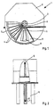
- Figs. 1 and 2 disclose an embodiment for removing the pulp cake from the sectors.
- sealing members are arranged at least at one point on the rim of disc 5 by which the pressure inside the casing is prevented from discharging to the loosening point of the pulp cake.
- the sealing member in the arrangement shown in Fig. 1 comprises a sectorlike plate 8, in the middle of which there is an opening 9 which is larger than the filter surface of the disc sector, through which opening 9 the pulp cake is dropped or transferred to be further treated.
- the plates 8 of two adjacent discs form a space 10 separated from the rest of treatment apparatus and opening (in the case of the figure) downwardly, through which space the pulp cake is discharged from the treatment apparatus.
- the size of the plates 8 depends on the sectors 4 of the disc 5 in such a way that plate 8 seals the inner space of casing 2 in all angle positions of the disc in such a way that the pressure cannot enter discharge space 10.
- space 10 is, of course, also sealed on the side of shaft 3 either by a curved or a straight plate 11.
- Fig. 3 shows a disc sector 40 of a preferred embodiment, which comprises a middle portion 41 with filter surfaces, and edge portions 42-45, which are raised relative to the middle portion, the outermost plane of which, relative to the wire surface, forms a sealing surface with the surface of the plate 8 on the disc side shown in the previous figures.
- the filter surface 41 of each sector 40 in a way forms the bottom surface of compartment 46, in which compartment the pulp cake is formed when the apparatus operates as a thickener.
- the height of the edge portions is advantageously defined in such a way that even in a maximum thickening process the thickness of the pulp cake does not exceed the height of the edge portions, in other words the pulp cake never touches the surface of plate 8. This is required, because otherwise the friction between the pulp cake and plate 8 would rapidly raise the energy consumption of the apparatus.
- the unbroken surface of plate 8 on both sides of opening 9 must be at least of the same size as sector 4 of disc 5 to prevent the pressure from escaping.
- high treatment pressure it is advantageous to arrange a broader unbroken portion on the plate, whereby one sealing surface does not have to bear the stress alone.
- high treatment pressures it may be necessary to arrange more removal and discharge points for the pulp cake on the rim of the disc, because the formation speed of a pulp cake is high.
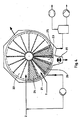
- Fig. 4 shows a preferred embodiment of the apparatus in accordance with the present invention, which is mainly aimed to be used for the recovery of so called zero fiber, in other words the fine dry substance which has been drawn in with the water removed from the web in a paper machine, or for like purpose.
- the surface of each disc is divided into several portions 21, 22, 23 by plates 24, 25 and 26 operating as sealing members.
- Long stock is fed into portion 21, which stock forms the so called basic stock on the wire surfaces, in other words a fiber layer which operates as a filter medium for the actual zero fiber being thickened, and on which the pulp cake is formed from the pulp including zero fibers.
- the sealing member in other words the plate 24 separates portion 21 from the actual thickening portion 22, which (in the case of the figure) is about 250 grades from the disc surface.
- the sealing member 25 separates portion 23 of the disc from thickening portion 22.
- Portion 23 is used to remove the pulp cake from the filter surface and the cake is discharged by transfer devices 27 further on.
- Discharge portion 23 is separated from the formation portion 21 for the basic stock by plate 26.
- each sealing member must have an annular breadth of at least the same size as the sector of the disc so as to fulfil the minimum requirements of sealing. If one desires to improve the sealing, said breadth of the sealing surface should advantageously be a multiple of the breadth of the disc sector. It may also be seen in the figure that the sealing members may be separated relative to one another or also in an embodiment they may form a uniform plate surface which has openings for the infeed and for the discharge of the pulp cake.
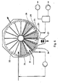
- Fig. 5 shows a scheme for the use of the apparatus of Fig. 4 for filtering zero water.
- Auxiliary pulp i.e. long stock, is fed from conduit 31 to the portion 21 of apparatus 1 of Fig. 4 for formation of the basic stock, and zero water is fed from conduit 32 for the actual thickening zone (22, Fig. 4).
- the initial filtrate 33 from the formation portion of the basic stock is guided through the infeed of zero water back to filtering apparatus 1, from which the clear filtrate is gathered from conduit 34.
- the filtrate from conduit 34 may be used for this purpose by taking part of it and by feeding it through pump 35 and conduit 36 back to the treatment apparatus.
- the removal of the pulp cake may be carried out from the inside of the sectors of the disc by guiding the water shower along the liquid discharge ducts of the shaft in the opposite direction relative to its conventional direction.
- a third principle alternative is, of course, different scraper arrangements, which may be arranged to wipe the wire surface when it is at the discharge opening, and to rise higher when the edge protrusions of the sectors pass under the scrapers.
- auxiliary pulp has been proved necessary in filtering zero water, because the filter medium will clog immediately at the beginning of the filtering stage without the pulp cake having time to be formed, if the filter medium is provided with so small perforations that zero fibers do not penetrate the medium.
- Fig. 6 shows yet another embodiment of the apparatus in accordance with the present invention, in which an additional sealing element 28 and a pulp treatment element 29 have been added to the apparatus as compared to Fig. 4.
- the sealing element 28 is similar previously described sealing elements, but element 29 may be used, for example, for the finishing drying of the pulp cake by blowing drying gas into the compartment so that the gas replaces liquid in the pulp cake. Such method is used when a high dry substance content is desired and the penetration of gas into the pulp does not cause any harm.
- washing also in such a way that the filtrate utilized to operate as washing liquid in each washing stage is not the filtrate of the immediately following stage, but that of some other following stage, whereby the difference in level of cleanliness between the washing liquid and the suspension to be treated is greater and the washing effect of the liquid is somewhat more efficient.
Abstract
Description
- The present invention relates to a method and apparatus for treating fiber suspension, in which method fiber suspension is fed to a pressurized treatment apparatus and in which the treatment is carried out under overpressurized conditions in an airless space. The method in accordance with the invention is applied to a new type of disc filter treatment apparatus, which is developed to operate in a pressurized state.
- There are, in principle, two different types of pulp treatment apparatuses known in the prior art. In most cases the most simple apparatus is a thickener, screen or washer operating under normal atmospheric pressure, whereby the apparatus does not have to be either pressure-proof or air-proof and whereby the transfer of liquid is carried out by means of reduced pressure. Thus the apparatus may be constructed considerably lighter, whereby the manufacturing costs remain relatively low and the acquisition of such an apparatus to the mills becomes economic. On the other hand due to the small pressure differences having an effect on the operation, in other words on the specific capacity, the apparatus has to be large so as to achieve a particular total capacity. In some cases it is also disadvantageous, particularly if air or like gas is included in the pulp to be treated. In order to at least partially eliminate said disadvantages pressurized pulp treatment apparatuses have been developed. Additionally, by using such apparatuses large filtrate tanks may be dispersed with.
- Only drum-type filters, thickeners and screens of the known pulp treatment apparatuses have generally been pressurized. The advantages achieved by them have been, for example, the space saved at the mills, a specific capacity which is considerably higher than that of the unpressurized apparatuses and the airlessness of the treatment space of the pulp, whereby the quality of the pulp remains better. It may even be considered that the capacity of a whole mill could be increased if the old unpressurized treatment apparatuses were to be replaced by new type of apparatuses operating with larger pressure differences.
- Since the drum-type pulp treatment apparatuses operating with overpressure have the same problems as the other drum-type apparatuses in other words, for example, a long retention time of the so called cloudy water in the treatment means before its possible return back to the means to be cleared. In the drum-type apparatuses fiber suspension is normally fed to the outer rim of the filter surface and the filtrate is discharged further on through the longitudinal channels of the cylinder, which are connected with each sector of the cylinder, and through valve members at the end of the cylinder both being inside the filter surface. If the cloudy liquid is desired to be returned back to the cylinder to be cleared, it has to be taken into consideration that the liquid has flowed long along channels which are several meters long to the end of the drum and from there further to the feed point. Thereby it is in practice impossible to divide the liquid flowing from the channel to cloudy and clear portions, in other words to a portion which is returned to the cylinder and a portion which is discharged from the means or fed into another stage, because the cloudy and the clear filtrate have probably already mixed with each other, whereby a lot of clear filtrate has to be returned back to the cylinder.
- Because the retention time of the filtrate is by disc-type apparatuses only a fraction of that of a drum-type apparatus, the disc-type pulp treatment apparatuses have recently become popular. At the same time, however, a higher specific capacity is required from them as well as better adjustability and clearer filtrate, whereby the pressurization of the appara tuses has become the only possibility. West German Patent Application 3.210.200 and U.S. Patent Specification 4,695,381 have distinctively illustrated reasons for pressurizing disc filters. When using underpressure for the discharge of liquid from the fiber suspension, a 6 to 10 m high drop leg is required in an unpressurized disc filter to create a sufficient underpressure inside the filter sectors. Therefore the filter has to be installed to said level to which the whole amount of the pulp to be treated has to be pumped. A second alternative for developing underpressure is naturally to use a vacuum pump, which however also adds costs. Additionally, the use of underpressure is restricted by the temperature of the fiber suspension to be treated, which may not rise over 80-90°C, because due to the underpressure the liquid would start to boil on the underpressure side. Also the maximal pressure difference is 101 kPa which, as commonly known, cannot be exceeded.
- Said prior publications illustrate a solution for eliminating or minimizing said problems, in which the pressure difference over the filter surfaces may be increased to the value of 300-400 kPa without any limitations as to the temperatures of the fiber suspensions to be treated. The apparatus comprises conventional filter disc units mounted on the shaft, which units are arranged inside a casing which may be pressurized. The pressure difference may be effected by a blower by which a desired overpressurized gas layer is generated in the upper part of a pressure vessel. The apparatus according to said U.S. patent includes also a control system by which the size of the gas layer is maintained as desired, in other words substantially the same as in conventional disc filters. Thus the only difference in the arrangement of said U.S. patent compared with the conventional disc filters is the pressure vessel operating as an outer casing of the apparatus and the overpressure created in the filter by a blower, by which arrangements a drop leg or a vacuum pump may be avoided and a higher pressure difference may be created over the filter surfaces, but there are now extra components, i.e. a blower, a pressure control system and a discharge and circulation system for air which has got into the filtrate, so altogether the apparatus has become even more complicated. Additionally, it has not been possible to eliminate from the apparatus the most well known defect in the disc filters, which is the considerably short length of the formation a pulp cake, about 180 - 200 grades of the whole rim of the filter disc, which considerably limits the specific capacity of the apparatus. On the other hand, this kind of guiding of pressurized air or like gas to communication with fiber suspension is not desirable in all cases, because the increase in the content of air in the suspension disturbs many processing stages by causing, for example, slime problems and making the pulp transfer by pumping more difficult.
- It has been possible to eliminate or minimize the defects of the arrangements according to the above mentioned publications by the method and apparatus in accordance with the invention, which are characterized in that the treatment of pulp is carried out in a closed pressurized apparatus, which has no gas space and no gas discharge and pressure control systems typical of the apparatus according to the above mentioned U.S. patent. Also the apparatus is characterized in that the filter surface in the apparatus can be utilized almost completely.
- The method in accordance with the present invention is characterized in that said treatment apparatus is filled with the mixture to be filtered so as to carry out the treatment in a closed airless space.
- The apparatus in accordance with the present invention is characterized in that the annular surface formed by a sequence of sectors with filter surfaces is divided into two or more portions separated from each other by members which are stationary relative to the casing of the apparatus, which members separate different treatment stages of fiber suspension from each other.
- The method and apparatus in accordance with the present invention are described below in greater detail, by way of example, with reference to the accompanying drawings, in which:
- Fig. 1 is a schematic partly sectional view of an embodiment of an apparatus in accordance with the present invention;
- Fig. 2 is an axial partly sectional view of the apparatus of Fig. 1;
- Fig. 3 is a preferred constructional alternative for the disc sector of an apparatus in accordance with the present invention;
- Fig. 4 is a schematic illustration of a second embodiment of an apparatus in accordance with the present invention;
- Fig. 5 is a schematic illustration of an alternative application of an embodiment of the apparatus in accordance with the present invention as shown in Fig. 4; and
- Fig. 6 is a schematic illustration of a further embodiment of an apparatus in accordance with the present invention.
- According to Figs. 1 and 2, the pulp treatment apparatus 1 in accordance with the present invention mainly comprises discs 5, which are formed by from sectors 4, arranged on a shaft 3, all being located within a substantially pressure-
proof casing 2. The sectors 4 are mounted on the shaft 3 in such a way that in shaft 3 each sector has its own discharge/inlet duct 6 each liquid, which communicates with a liquid compartment 7 of each sector, which is defined in a known way by filter surfaces. According to the invention, the fiber suspension to be treated is fed in a pressurized manner into the interior of thecasing 2 so that the space within the casing is filled with suspension. - As can be noted the retention time of the filtrate of an apparatus in accordance with the present invention is, for example, in thickening use very short. When guiding the filtrate liquid via the shaft out of the sectors, the liquid must, at its maximum, flow only alone the length of the shaft to reach valve means located outside the apparatus, wherefrom the liquid is transferred for further treatment. Thus there is no time for the cloudy and clear filtrate to be mixed with each other, and the amount of cloudy filtrate, which may possibly be returned to the apparatus, hardly differs from the actual amount of the cloudy filtrate. It is also possible to facilitate the flow of the liquid to the valve means by arranging the valve to the middle part of the apparatus, in other words to the middle portion of the shaft, whereby the above mentioned retention times are halved. The situation becomes even more advantageous when the filtrate liquid or like is guided outwardly from the liquid compartment of the sector to the outer rim of the sector, to which a valve means may be mounted, by which the run of the liquid is guided either back to some part of the apparatus, to the treatment zone or out of the apparatus. Respectively, it is possible to arrange corresponding separate valve means for each sector to the junction point of each sector and the shaft, which valve corresponding to the previous embodiment guides the flow of the liquid. In the two last mentioned cases the retention time of the liquid in the apparatus is minimized in such a way that the only factor affecting the retention time is the time passing in the flow of the liquid from the end of the sector which is opposite relative to the valve apparatus to the valve means.
- When using the apparatus in accordance with the present invention as a thickener, the pressure in the fiber suspension causes the liquid pressing through the filter surfaces of the sectors to the liquid compartment 7, through discharge duct 6 and finally out from the whole apparatus. Thereby the filter surface of the disc filter is almost completely efficiently used. The surface of the disc is almost completely available to be used for the liquid discharge with the only exception of the part or those sections, in which the thickened pulp cake is at a particular moment being discharged. Figs. 1 and 2 disclose an embodiment for removing the pulp cake from the sectors. On both sides of each filter disc 5 sealing members are arranged at least at one point on the rim of disc 5 by which the pressure inside the casing is prevented from discharging to the loosening point of the pulp cake. The sealing member in the arrangement shown in Fig. 1 comprises a sectorlike plate 8, in the middle of which there is an
opening 9 which is larger than the filter surface of the disc sector, through which opening 9 the pulp cake is dropped or transferred to be further treated. The plates 8 of two adjacent discs form aspace 10 separated from the rest of treatment apparatus and opening (in the case of the figure) downwardly, through which space the pulp cake is discharged from the treatment apparatus. Thus the space insidecasing 2 in the area of plates 8 has no fiber suspension at all. The size of the plates 8 depends on the sectors 4 of the disc 5 in such a way that plate 8 seals the inner space ofcasing 2 in all angle positions of the disc in such a way that the pressure cannot enterdischarge space 10. Thusspace 10 is, of course, also sealed on the side of shaft 3 either by a curved or astraight plate 11. - Fig. 3 shows a disc sector 40 of a preferred embodiment, which comprises a
middle portion 41 with filter surfaces, and edge portions 42-45, which are raised relative to the middle portion, the outermost plane of which, relative to the wire surface, forms a sealing surface with the surface of the plate 8 on the disc side shown in the previous figures. Thus thefilter surface 41 of each sector 40 in a way forms the bottom surface of compartment 46, in which compartment the pulp cake is formed when the apparatus operates as a thickener. The height of the edge portions is advantageously defined in such a way that even in a maximum thickening process the thickness of the pulp cake does not exceed the height of the edge portions, in other words the pulp cake never touches the surface of plate 8. This is required, because otherwise the friction between the pulp cake and plate 8 would rapidly raise the energy consumption of the apparatus. - As was mentioned above, the unbroken surface of plate 8 on both sides of
opening 9 must be at least of the same size as sector 4 of disc 5 to prevent the pressure from escaping. When using high treatment pressure, it is advantageous to arrange a broader unbroken portion on the plate, whereby one sealing surface does not have to bear the stress alone. On the other hand, when high treatment pressures are used it may be necessary to arrange more removal and discharge points for the pulp cake on the rim of the disc, because the formation speed of a pulp cake is high. Thus by arranging several discharge points it is possible to reduce the rotational speed of the discs. - Fig. 4 shows a preferred embodiment of the apparatus in accordance with the present invention, which is mainly aimed to be used for the recovery of so called zero fiber, in other words the fine dry substance which has been drawn in with the water removed from the web in a paper machine, or for like purpose. The surface of each disc is divided into
several portions plates portion 21, which stock forms the so called basic stock on the wire surfaces, in other words a fiber layer which operates as a filter medium for the actual zero fiber being thickened, and on which the pulp cake is formed from the pulp including zero fibers. The sealing member, in other words theplate 24separates portion 21 from the actual thickeningportion 22, which (in the case of the figure) is about 250 grades from the disc surface. The sealingmember 25separates portion 23 of the disc from thickeningportion 22.Portion 23 is used to remove the pulp cake from the filter surface and the cake is discharged bytransfer devices 27 further on. -
Discharge portion 23 is separated from theformation portion 21 for the basic stock byplate 26. As has become clear from above, each sealing member must have an annular breadth of at least the same size as the sector of the disc so as to fulfil the minimum requirements of sealing. If one desires to improve the sealing, said breadth of the sealing surface should advantageously be a multiple of the breadth of the disc sector. It may also be seen in the figure that the sealing members may be separated relative to one another or also in an embodiment they may form a uniform plate surface which has openings for the infeed and for the discharge of the pulp cake. - Fig. 5 shows a scheme for the use of the apparatus of Fig. 4 for filtering zero water. Auxiliary pulp, i.e. long stock, is fed from
conduit 31 to theportion 21 of apparatus 1 of Fig. 4 for formation of the basic stock, and zero water is fed fromconduit 32 for the actual thickening zone (22, Fig. 4). Theinitial filtrate 33 from the formation portion of the basic stock is guided through the infeed of zero water back to filtering apparatus 1, from which the clear filtrate is gathered fromconduit 34. If the thickened pulp cake is removed by utilizing water showers, the filtrate fromconduit 34 may be used for this purpose by taking part of it and by feeding it throughpump 35 andconduit 36 back to the treatment apparatus. The removal of the pulp cake may be carried out from the inside of the sectors of the disc by guiding the water shower along the liquid discharge ducts of the shaft in the opposite direction relative to its conventional direction. - As for the removal of the pulp cake from filter surfaces in cases which use the apparatus as a thickener, it is possible to use clear filtrate in loosening the cake, which filtrate is guided through the filtrate duct or like of the shaft 3 back to the inside of the disc sectors and which is pressed through the openings of the filter surface and pushes the pulp cake loose from the filter surface and at the same time flushes the filter medium. Naturally, it also is possible to blow also gas along the same duct network so as to loosen the pulp cake.
- It is also easy to arrange means for a liquid shower operating on a conventional principle to spread either water from a separate well or clear filtrate between the filter surface and the pulp cake. A third principle alternative is, of course, different scraper arrangements, which may be arranged to wipe the wire surface when it is at the discharge opening, and to rise higher when the edge protrusions of the sectors pass under the scrapers.
- It is possible to use the apparatus in accordance with the present invention for filtering zero fiber without a separate infeed of auxiliary pulp so that the auxiliary pulp is continuously fed together with the zero water, whereby zero fibers penetrate the wire surface at the beginning of the thickening stage. However, the additional pulp quickly forms basic stock on the wire surface, whereby the zero fibers no longer penetrate the filter medium. The basic stock is formed in reality so rapidly that even this kind of solution is possible, because the amount of cloudy filtrate does not increase excessively. The use of auxiliary pulp has been proved necessary in filtering zero water, because the filter medium will clog immediately at the beginning of the filtering stage without the pulp cake having time to be formed, if the filter medium is provided with so small perforations that zero fibers do not penetrate the medium.
- Fig. 6 shows yet another embodiment of the apparatus in accordance with the present invention, in which an
additional sealing element 28 and apulp treatment element 29 have been added to the apparatus as compared to Fig. 4. The sealingelement 28 is similar previously described sealing elements, butelement 29 may be used, for example, for the finishing drying of the pulp cake by blowing drying gas into the compartment so that the gas replaces liquid in the pulp cake. Such method is used when a high dry substance content is desired and the penetration of gas into the pulp does not cause any harm. - In a corresponding way it is possible to add compartments separated by sealing members for different purposes, such as, for example, for washing the filter medium or if the apparatus is used as a pulp washer, it is possible to carry out all the stages required for the washing in one apparatus by arranging a sufficient amount of different zones, in other words pulp treatment elements. It is possible to use the apparatus as a multi-stage washer, for example in such a way that the fiber suspension to be treated is fed in the washing order to the first treatment compartment, to which filtrate from the second treatment compartment in the washing order is guided as a washing liquid. The suspension is then transferred by the rotation of the treatment disc to the second treatment stage, to which filtrate of the third treatment stage is guided as a washing liquid. The process continues in such way until the fiber suspension reaches a sufficient level of cleanliness, after which it is discharged from the apparatus.
- It is, of course, possible to arrange the washing also in such a way that the filtrate utilized to operate as washing liquid in each washing stage is not the filtrate of the immediately following stage, but that of some other following stage, whereby the difference in level of cleanliness between the washing liquid and the suspension to be treated is greater and the washing effect of the liquid is somewhat more efficient.
- As is seen from the above description, a new many-sided pulp treatment apparatus is developed which eliminates or minimizes the drawbacks of the apparatuses of the prior art techniques, and the above description shows only a few embodiments of the apparatus which are not intended to restrict the scope of invention from that given in the accompanying claims.
Claims (20)
Priority Applications (1)
| Application Number | Priority Date | Filing Date | Title |
|---|---|---|---|
| AT88310201T ATE73509T1 (en) | 1987-11-05 | 1988-10-31 | METHOD AND APPARATUS FOR TREATMENT OF A FIBER SUSPENSION. |
Applications Claiming Priority (2)
| Application Number | Priority Date | Filing Date | Title |
|---|---|---|---|
| FI874887A FI81725C (en) | 1987-11-05 | 1987-11-05 | Method and apparatus for treating fiber suspension |
| FI874887 | 1987-11-05 |
Publications (3)
| Publication Number | Publication Date |
|---|---|
| EP0315388A2 true EP0315388A2 (en) | 1989-05-10 |
| EP0315388A3 EP0315388A3 (en) | 1989-05-31 |
| EP0315388B1 EP0315388B1 (en) | 1992-03-11 |
Family
ID=8525361
Family Applications (1)
| Application Number | Title | Priority Date | Filing Date |
|---|---|---|---|
| EP88310201A Expired - Lifetime EP0315388B1 (en) | 1987-11-05 | 1988-10-31 | Method and apparatus for treating fiber suspension |
Country Status (6)
| Country | Link |
|---|---|
| US (1) | US5073264A (en) |
| EP (1) | EP0315388B1 (en) |
| AT (1) | ATE73509T1 (en) |
| DE (1) | DE3869061D1 (en) |
| FI (1) | FI81725C (en) |
| NO (1) | NO884949L (en) |
Families Citing this family (8)
| Publication number | Priority date | Publication date | Assignee | Title |
|---|---|---|---|---|
| US5192454A (en) * | 1987-11-05 | 1993-03-09 | A. Ahlstrom Corporation | Method for treating fiber suspension |
| SE463242B (en) * | 1989-03-13 | 1990-10-29 | Hedemora Ab | FILTER FOR CONTINUOUS SUSPENSION FILTERING |
| US5934476A (en) * | 1996-08-21 | 1999-08-10 | Roe; Philippe | Vacuum rotary filtration apparatus |
| FI106386B (en) * | 1999-05-03 | 2001-01-31 | Valmet Corp | Method and apparatus for recovering fibers from recycled water in a paper mill |
| DE102004033328A1 (en) * | 2004-07-09 | 2006-02-09 | Bhs-Sonthofen Gmbh | Filter with solid resuspension |
| FI122775B (en) | 2004-09-07 | 2012-06-29 | Andritz Oy | Apparatus and method for treating pulp |
| SE528722C2 (en) * | 2005-06-03 | 2007-01-30 | Metso Paper Inc | Apparatus for treating cellulose pulp in a washing apparatus provided with a reinforcing sheath |
| AT505247B1 (en) * | 2007-05-30 | 2009-01-15 | Andritz Ag Maschf | VACUUM-SUPPORTED DRAINAGE PROCESS AND ROTATING FILTER FOR CARRYING OUT THE DRAINAGE PROCESS |
Citations (6)
| Publication number | Priority date | Publication date | Assignee | Title |
|---|---|---|---|---|
| DE3020119A1 (en) * | 1980-05-27 | 1981-12-10 | Envirotech Corp., Menlo Park, Calif. | Washing machine for fibrous material, e.g. paper pulp - provides vacuum filtration, and eliminates re-grinding |
| US4330405A (en) * | 1980-09-29 | 1982-05-18 | Davis Kent L | Vacuum disc filter |
| DE3210200A1 (en) * | 1980-09-30 | 1983-09-29 | Rauma Repola Oy | Process for thickening a pulp mixture or a sludge and a disc filter for application of the process |
| WO1985004433A1 (en) * | 1984-04-03 | 1985-10-10 | Sunds Defibrator Aktiebolag | Method and apparatus for processing material suspensions |
| EP0166663A1 (en) * | 1984-05-14 | 1986-01-02 | Aluminium Pechiney | Stream-down feeding means for rotating-disc filters |
| US4695381A (en) * | 1985-05-02 | 1987-09-22 | Ab Hedemora Verkstader | Filter for continuous filtering of a suspension under pressure |
Family Cites Families (10)
| Publication number | Priority date | Publication date | Assignee | Title |
|---|---|---|---|---|
| US1649581A (en) * | 1921-04-29 | 1927-11-15 | United Filters Corp | Method and means for removing filter cakes from filter mediums |
| US2115211A (en) * | 1934-08-09 | 1938-04-26 | Texas Co | Continuous filtration of wax bearing oil |
| FR796609A (en) * | 1935-01-07 | 1936-04-11 | Alsacienne Constr Meca | Filter improvement |
| US2055119A (en) * | 1935-02-16 | 1936-09-22 | Karl R Clendening | Starch mill reel |
| US2027652A (en) * | 1935-04-25 | 1936-01-14 | Municipal Sanitary Service Cor | Filter |
| US2500056A (en) * | 1945-12-20 | 1950-03-07 | Standard Oil Dev Co | Method and apparatus for solventcleaning finely divided solids |
| US3152986A (en) * | 1960-08-03 | 1964-10-13 | Phillips Petroleum Co | Filtering process and apparatus |
| US3504802A (en) * | 1967-05-08 | 1970-04-07 | Improved Machinery Inc | Rotary drum filter |
| BR5900592U (en) * | 1979-04-30 | 1980-11-04 | Voith Sa Maquinas Equip | CELL DRUM FILTER TO DELETE SUSPENSIONS |
| JPH01222515A (en) * | 1988-03-02 | 1989-09-05 | Matsushita Electron Corp | Semiconductor integrated circuit device |
-
1987
- 1987-11-05 FI FI874887A patent/FI81725C/en not_active IP Right Cessation
-
1988
- 1988-10-31 AT AT88310201T patent/ATE73509T1/en not_active IP Right Cessation
- 1988-10-31 DE DE8888310201T patent/DE3869061D1/en not_active Expired - Lifetime
- 1988-10-31 EP EP88310201A patent/EP0315388B1/en not_active Expired - Lifetime
- 1988-11-04 NO NO88884949A patent/NO884949L/en unknown
-
1990
- 1990-06-26 US US07/544,032 patent/US5073264A/en not_active Expired - Lifetime
Patent Citations (6)
| Publication number | Priority date | Publication date | Assignee | Title |
|---|---|---|---|---|
| DE3020119A1 (en) * | 1980-05-27 | 1981-12-10 | Envirotech Corp., Menlo Park, Calif. | Washing machine for fibrous material, e.g. paper pulp - provides vacuum filtration, and eliminates re-grinding |
| US4330405A (en) * | 1980-09-29 | 1982-05-18 | Davis Kent L | Vacuum disc filter |
| DE3210200A1 (en) * | 1980-09-30 | 1983-09-29 | Rauma Repola Oy | Process for thickening a pulp mixture or a sludge and a disc filter for application of the process |
| WO1985004433A1 (en) * | 1984-04-03 | 1985-10-10 | Sunds Defibrator Aktiebolag | Method and apparatus for processing material suspensions |
| EP0166663A1 (en) * | 1984-05-14 | 1986-01-02 | Aluminium Pechiney | Stream-down feeding means for rotating-disc filters |
| US4695381A (en) * | 1985-05-02 | 1987-09-22 | Ab Hedemora Verkstader | Filter for continuous filtering of a suspension under pressure |
Also Published As
| Publication number | Publication date |
|---|---|
| FI874887A0 (en) | 1987-11-05 |
| EP0315388B1 (en) | 1992-03-11 |
| NO884949D0 (en) | 1988-11-04 |
| FI81725B (en) | 1990-08-31 |
| ATE73509T1 (en) | 1992-03-15 |
| NO884949L (en) | 1989-05-08 |
| US5073264A (en) | 1991-12-17 |
| DE3869061D1 (en) | 1992-04-16 |
| FI81725C (en) | 1990-12-10 |
| EP0315388A3 (en) | 1989-05-31 |
| FI874887A (en) | 1989-05-06 |
Similar Documents
| Publication | Publication Date | Title |
|---|---|---|
| US4952314A (en) | Apparatus for treating pulp | |
| US5046338A (en) | Multiphase pulp washer | |
| US4136028A (en) | Method for filtering a fibrous material by means of a disc filter as well as a disc filter for performing the method | |
| US5382327A (en) | Apparatus for thickening pulp and paper stock | |
| FI68678C (en) | PROOF OF ORIGINATION FOR THE PURPOSE OF THE PAPER | |
| CA2021210C (en) | Adjustable valve for filters | |
| EP0315388B1 (en) | Method and apparatus for treating fiber suspension | |
| CA1330207C (en) | Reject screen | |
| CA2160536C (en) | Anti-rewet deck for press rolls | |
| NO178269B (en) | Apparatus and method for treating a suspension of fibrous cellulose material | |
| CA1321094C (en) | Method and apparatus for treating fiber suspensions | |
| CA1225267A (en) | Method and apparatus for washing paper pulp | |
| US5192454A (en) | Method for treating fiber suspension | |
| US5139671A (en) | Apparatus for treating pulp | |
| US5674396A (en) | Rotary filter with a device for separating a solids/liquid mixture, particularly a pulp suspension | |
| US4539827A (en) | Belt washing improvements | |
| US4608122A (en) | Method for washing a paper fiber on a belt washer using a sonic frequency disturbance | |
| US4217170A (en) | Pulp washer discharging a low consistency pulp slurry | |
| EP0298499B1 (en) | Method and apparatus for thickening fiber suspension | |
| US2802572A (en) | Screen unit for treating solid matter of a suspension | |
| US5186791A (en) | Apparatus for thickening pulp and paper stock | |
| EP0793750A1 (en) | Apparatus and process for screening a fibre suspension and process for producing paper utilizing the same | |
| CA2172257C (en) | Cross braced vacuum washer | |
| US5034120A (en) | Method for keeping a screen or filter surface clear | |
| US5203968A (en) | Apparatus for treating fiber suspensions having rotatable liquid permeable treatment ducts |
Legal Events
| Date | Code | Title | Description |
|---|---|---|---|
| PUAI | Public reference made under article 153(3) epc to a published international application that has entered the european phase |
Free format text: ORIGINAL CODE: 0009012 |
|
| PUAL | Search report despatched |
Free format text: ORIGINAL CODE: 0009013 |
|
| 17P | Request for examination filed |
Effective date: 19881122 |
|
| AK | Designated contracting states |
Kind code of ref document: A2 Designated state(s): AT DE SE |
|
| RHK1 | Main classification (correction) |
Ipc: D21D 5/02 |
|
| AK | Designated contracting states |
Kind code of ref document: A3 Designated state(s): AT DE SE |
|
| 17Q | First examination report despatched |
Effective date: 19900911 |
|
| GRAA | (expected) grant |
Free format text: ORIGINAL CODE: 0009210 |
|
| AK | Designated contracting states |
Kind code of ref document: B1 Designated state(s): AT DE SE |
|
| PG25 | Lapsed in a contracting state [announced via postgrant information from national office to epo] |
Ref country code: AT Effective date: 19920311 |
|
| REF | Corresponds to: |
Ref document number: 73509 Country of ref document: AT Date of ref document: 19920315 Kind code of ref document: T |
|
| REF | Corresponds to: |
Ref document number: 3869061 Country of ref document: DE Date of ref document: 19920416 |
|
| PLBE | No opposition filed within time limit |
Free format text: ORIGINAL CODE: 0009261 |
|
| STAA | Information on the status of an ep patent application or granted ep patent |
Free format text: STATUS: NO OPPOSITION FILED WITHIN TIME LIMIT |
|
| 26N | No opposition filed | ||
| EAL | Se: european patent in force in sweden |
Ref document number: 88310201.4 |
|
| PGFP | Annual fee paid to national office [announced via postgrant information from national office to epo] |
Ref country code: DE Payment date: 20050919 Year of fee payment: 18 |
|
| PGFP | Annual fee paid to national office [announced via postgrant information from national office to epo] |
Ref country code: SE Payment date: 20050921 Year of fee payment: 18 |
|
| PG25 | Lapsed in a contracting state [announced via postgrant information from national office to epo] |
Ref country code: SE Free format text: LAPSE BECAUSE OF NON-PAYMENT OF DUE FEES Effective date: 20061101 |
|
| PG25 | Lapsed in a contracting state [announced via postgrant information from national office to epo] |
Ref country code: DE Free format text: LAPSE BECAUSE OF NON-PAYMENT OF DUE FEES Effective date: 20070501 |
|
| EUG | Se: european patent has lapsed |