EP0314589A1 - Warning device for buried conduits - Google Patents
Warning device for buried conduits Download PDFInfo
- Publication number
- EP0314589A1 EP0314589A1 EP88420369A EP88420369A EP0314589A1 EP 0314589 A1 EP0314589 A1 EP 0314589A1 EP 88420369 A EP88420369 A EP 88420369A EP 88420369 A EP88420369 A EP 88420369A EP 0314589 A1 EP0314589 A1 EP 0314589A1
- Authority
- EP
- European Patent Office
- Prior art keywords
- elements
- strip
- sheaths
- signaling
- series
- Prior art date
- Legal status (The legal status is an assumption and is not a legal conclusion. Google has not performed a legal analysis and makes no representation as to the accuracy of the status listed.)
- Granted
Links
Images

Classifications
-
- H—ELECTRICITY
- H02—GENERATION; CONVERSION OR DISTRIBUTION OF ELECTRIC POWER
- H02G—INSTALLATION OF ELECTRIC CABLES OR LINES, OR OF COMBINED OPTICAL AND ELECTRIC CABLES OR LINES
- H02G9/00—Installations of electric cables or lines in or on the ground or water
- H02G9/02—Installations of electric cables or lines in or on the ground or water laid directly in or on the ground, river-bed or sea-bottom; Coverings therefor, e.g. tile
- H02G9/025—Coverings therefor, e.g. tile
Definitions
- the present invention relates to a device for warning buried pipelines.
- the signaling device only plays its role imperfectly, and the operator of the shovel may not see the signaling device and thus not be alerted to the presence of an underlying pipe.
- strip (s) forming part of this marking material.
- metals which may or may not be protected against corrosion can be used, synthetic materials which may or may not be oriented, woven fibers or not.
- the support of this or these bands can also be made of various materials, such as: - polyvinyl chloride, polyethylene, polypropylene, synthetic fibers, - cotton ... and it can come in various forms: - perforated film or not, - wire mesh, - tablecloth: woven or not or other supports such as those used for soil stabilization.
- the present invention aims to remedy these drawbacks by providing a device for signaling and locating buried pipelines, capable of being laid mechanically.
- the device which it relates comprises at least one series of signaling elements constituted by sections of elongated strips, made of a flexible material and having good tensile strength, arranged one after the other, each series of strip sections being housed inside a continuous sheath.
- the various signaling elements of the same series are constituted by several sections of strips separated from each other.
- the different signaling elements of the same series consist of several sections of the same strip separated from each other by precut or break lines, regularly distributed over the length of the strip .
- this device comprises at least two parallel series of strip sections, of the same unit length or not, housed in a corresponding number of sheaths integral with each other, the strip sections of the different series being offset longitudinally relative to each other. other.
- the locating elements being arranged inside one or more continuous sheaths are perfectly protected, thus allowing the installation of the device using an apparatus such as a "plow-mole" for example, the essential being that the mechanical characteristics of the sheath meet the requirements of installation.
- This sliding characteristic is particularly important, because the strip sections, in total or partial contact with the ground, do not have this sliding ability and do not certainly allow the taking of at least one strip section by the bucket of the device.
- the strip sections in total or partial contact with the ground, do not have this sliding ability and do not certainly allow the taking of at least one strip section by the bucket of the device.
- the rest of the section slides in the sheath and is evacuated by the bucket, overflowing the contents thereof, and is immediately visible to the operator.
- this device further comprises at least one continuous strip forming a signaling element, of homo structure. gene over its entire length, made of a flexible material and having good resistance to rupture, housed inside a continuous sheath.
- this device comprises three parallel sheaths integral with one another, the central sheath of which serves as a housing for a continuous strip, and the two lateral sheaths of which serve as housing for two series of signaling elements constituted by strip sections.
- the sheaths containing signaling elements are produced from two continuous ribbons of synthetic material, joined to one another after positioning of the signaling elements by longitudinal welds, the number of welds being equal to number of ribbons increased by one.
- the sheaths containing signaling elements are produced from a continuous ribbon of synthetic material, folded back on itself along a central and longitudinal line, after positioning the signaling elements, the two thicknesses tape being joined to each other by longitudinal welds, the number of which is equal to the number of sheaths.
- thermo welds may be high-frequency thermal welds, with or without the addition of material, depending on the material used, which may for example be chosen from polyvinyl chloride, polyethylene, polypropylene, polyester, etc.
- this device includes detection elements, such as conductive elements, metallic wire, insulated or not, magnetic system, electronic system or inductive system, arranged in a sheath or under a film integral with the sheaths. containing the signaling elements, or in the mass of the material constituting the warning device.
- detection elements such as conductive elements, metallic wire, insulated or not, magnetic system, electronic system or inductive system, arranged in a sheath or under a film integral with the sheaths. containing the signaling elements, or in the mass of the material constituting the warning device.
- the magnetic elements can be constituted by magnets in the form of wire of materials having magnetic properties, by parallelepipedic or cylindrical elements based on magnetic iron oxide or in other materials with durable detection properties.
- the signaling device represented in FIGS. 1 and 2, comprises two series of signaling elements constituted by sections of strip 2 .
- Each strip section which may have a length of the order of 1.70 meters and a width of the order of 2 centimeters for example, is made of a flexible material and having good resistance to breakage. It is thus possible to use metals protected or not against corrosion, oriented or non-oriented synthetic materials or woven or non-woven fibers.
- the two series of signaling elements are parallel and the elements of one series are offset longitudinally with respect to the elements of the other series.
- each series of signaling elements is disposed inside a continuous sheath 3 , and having sufficient mechanical strength to allow automatic laying using an apparatus such as a plow -mole, for example.
- the two sheaths 3 containing the two series of signaling elements are constituted by a lower strip 4 and an upper strip 5 .
- three longitudinal welds are made, respectively, 6 at the two edges of the strips 4 and 5 , and 7 at mid -width of these.
- FIG. 3 represents an alternative embodiment of this device in which the same elements are designated by the same references as above, the only difference residing in the fact that the sheaths 3 are obtained from a single ribbon 8 folded longitudinally over itself in the middle of its width 9 , with care of the two sheaths by a weld 6 at its edge and an intermediate weld 7 .
- FIG. 4 represents a device similar to that of FIG. 1, in which is included a detection element 10 constituted for example by a metallic wire, insulated or not, a magnetic system, a system inductive or a passive electronic system.
- a detection element 10 constituted for example by a metallic wire, insulated or not, a magnetic system, a system inductive or a passive electronic system.
- an intermediate sheath 12 is provided containing the detection element 10 , this intermediate sheath being obtained by providing two intermediate welds 7a, 7b instead of one in the previous case.
- Figure 5 is a view corresponding to Figure 2 showing an embodiment of this device using two ribbons 4 and 5
- Figure 6 is a view similar to Figure 3 showing the embodiment of this device using a single ribbon 8 folded longitudinally on itself.
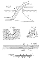
- FIG. 7 represents the ploughshare 13 of a mole plow, comprising not only a conduit 14 for the passage of the pipe 15 to be buried, but also a conduit 16 for the passage of the signaling device designated in this figure by the general reference 17 .
- This signaling device perfectly fulfills its role during the execution of a search or trench by a mechanical shovel.
- the bucket 18 of the shovel takes the earth from the trench 19 , it exerts on the device sufficient traction to cause the sheaths to rupture 3 .
- Signaling elements 2 are not affected by this rupture, on the one hand, because they are made of a material with high resistance to rupture and, on the other hand, due to the fact that they consist of a plurality of independent elements placed end to end.
- the width of the signaling device depends on the diameter of the underlying pipe (s). If it is a question of signaling small diameter pipes, it is possible to advantageously use a device such as that shown in FIGS. 1 to 6, which has a width of the order of 5 centimeters.
- a device can include three parallel series of signaling elements which are shown in section in FIG. 11, the three sheaths associated with these three series being obtained, in the embodiment shown, from two continuous strips 4 and 5 joined at their ends by two welds 6 as well as by two welds intermediaries 7 .
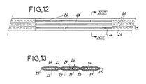
- the warning device shown in FIGS. 12 and 13, comprises three continuous sheaths 22 , constituted by a lower strip 23 and an upper strip 24 joined to one another by four longitudinal welds 25 delimiting the three sheaths 22 .
- Each of the two lateral sheaths contains several sections of strip 26 arranged in the extension of each other, each section of strip made of a flexible material and having a good breaking strength which may have, for example, a length of 1.70 meters. and a width of the order of 1 cm.
- the central sheath contains a continuous strip 27 of homogeneous structure over its entire length, made of a flexible material and having good resistance to rupture.
- This warning device therefore has a double signaling capacity, on the one hand, using the strip sections 26 capable of being easily hooked by the tool with which the trench is made and, on the other hand, to the using the continuous strip (s) which are broken by the tool and which remain in the bottom of the trench.
- the invention brings a great improvement to the existing technique by providing a simple structure device originally presented in a continuous form allowing mechanical installation, while benefiting from the tracking qualities provided by 'firstly by signaling elements distinct from each other, and secondly by detection elements.
- the number of series of signaling elements, the dimensions thereof, which can be variable from one series of elements to another, the structure of the signaling elements which may be constituted by strips having transverse breaking lines, or the fixing of the detection elements, could be different without leaving the part of the invention.
Abstract
Description
La présente invention a pour objet un dispositif avertisseur de canalisations enterrées.The present invention relates to a device for warning buried pipelines.
Pour faciliter, lors de fouilles, la signalisation et le repérage des canalisations enterrées, il est habituel d'enterrer, au-dessus des canalisations, des dispositifs de signalisation se présentant, le plus souvent, sous la forme de grillages réalisés en matière synthétique.To facilitate, during excavations, the signaling and location of buried pipelines, it is usual to bury, above the pipelines, signaling devices most often in the form of gratings made of synthetic material.
Il est, en outre, connu d'associer à ces grillages des éléments en forme de bandes longitudinales continues et rectilignes qui ont des résistances à l'allongement et à la rupture différentes de celles du grillage.It is also known to associate with these grids elements in the form of continuous and rectilinear longitudinal strips which have resistance to elongation and to rupture different from those of the grating.
Cette association, qui est destinée à faciliter la signalisation lorsque les fouilles sont faites à la pelle mécanique, ne permet pas toujours en fait d'atteindre ce but. L'expérience prouve, en effet, que souvent, lors de la rupture du grillage et des bandes par le godet de la pelle, les morceaux de bande arrachés par le godet disparaissent dans les matériaux saisis, et les bandes restant sur les parois de la fouille peuvent être peu visibles.This association, which is intended to facilitate signaling when excavations are carried out with a mechanical shovel, does not always in fact achieve this goal. Experience has shown, in fact, that often when the mesh and the bands are broken by the bucket of the shovel, the pieces of band torn off by the bucket disappear in the material seized, and the bands remaining on the walls of the excavation may be barely visible.
Si tel est le cas, le dispositif de signalisation ne joue plus qu'imparfaitement son rôle, et le conducteur de la pelle peut ne pas voir le dispositif de signalisation et ainsi ne pas être alerté de la présence d'une canalisation sous-jacente.If this is the case, the signaling device only plays its role imperfectly, and the operator of the shovel may not see the signaling device and thus not be alerted to the presence of an underlying pipe.
Il en est d'ailleurs de même lorsque la fouille est faite dans un terrain meuble qui, en s'éboulant de lui-même, masque les deux extrémités de chaque bande, en les dissimulant à la vue du conducteur.It is also the same when the search is made in loose ground which, by collapsing on its own, masks the two ends of each strip, hiding them from the driver's view.
Il arrive enfin, que le godet de la pelle découpe de façon très nette les bandes associées au grillage ; le conducteur ne voit alors les bandes ni dans les parois de la fouille, ni dans la masse de matériaux contenue dans la pelle. Malgré leur intérêt, les bandes longitudinales associées au grillage ne permettent donc pas de garantir, systématiquement, lors des fouilles, notamment lors des fouilles réalisées à la pelle mécanique, une signalisation certaine des canalisations placées sous le grillage.Finally, it happens that the bucket of the shovel very clearly cuts the strips associated with the mesh; the driver then sees the strips neither in the walls of the excavation, nor in the mass of materials contained in the shovel. Despite their interest, the longitudinal strips associated with the fence therefore do not guarantee, systematically, during excavations, in particular during excavations carried out with a mechanical shovel, certain signaling of the pipes placed under the fence.
Le brevet français 83 14438 au nom de la Demanderesse a proposé des solutions pour pallier les difficultés énoncées précédemment. Ce brevet décrit un matériau de repérage du type précité, et dans lequel l'élément de repérage est constitué par au moins une bande rectiligne, mais discontinue, réalisée en une matière ayant une bonne résistance à la rupture et associée à un support ayant une faible résistance à la rupture.French patent 83 14438 in the name of the Applicant has proposed solutions to overcome the difficulties set out above. This patent describes a locating material of the aforementioned type, and in which the locating element is constituted by at least one rectilinear, but discontinuous strip, made of a material having a good breaking strength and associated with a support having a low breaking strength.
Diverses matières sont utilisables pour réaliser la ou les bandes entrant dans la constitution de ce matériau de repérage. C'est ainsi que peuvent notamment être utilisés des métaux protégés ou non contre la corrosion, des matières synthétiques orientées ou non, des fibres tissées ou non.Various materials can be used to make the strip (s) forming part of this marking material. Thus, in particular, metals which may or may not be protected against corrosion can be used, synthetic materials which may or may not be oriented, woven fibers or not.
Quant au support de cette ou de ces bandes, il peut aussi être réalisé en diverses matières, telles que :
- chlorure de polyvinyle, polyéthylène, polypropylène, fibres synthétiques,
- coton...
et il peut se présenter sous diverses formes :
- film perforé ou non,
- grillage,
- nappe : tissée ou non
ou autres supports du type de ceux utilisés pour la stabilisation des sols.As for the support of this or these bands, it can also be made of various materials, such as:
- polyvinyl chloride, polyethylene, polypropylene, synthetic fibers,
- cotton ...
and it can come in various forms:
- perforated film or not,
- wire mesh,
- tablecloth: woven or not
or other supports such as those used for soil stabilization.
Les différentes formes d'exécution décrites dans le brevet précité permettent d'atteindre le but recherché, mais ont toutes, en commun, une mauvaise aptitude à la pose mécanisée des canalisations enterrées dans laquelle le système de signalisation étant saisi par l'outil, la traction exercée sur lui provoque successivement son allongement et sa rupture ; ce qui provoque la séparation de la ou des autres bandes qui sont non pas continues, mais discontinues. Il en résulte que des morceaux de bandes se trouvent alors séparés. Ce sont précisément ces morceaux de bandes qui, constituant des éléments de signalisation, apparaissent très visiblement hors des parois d'une tranchée, hors d'un talus d'éboulement ou hors du godet d'une pelle.The various embodiments described in the aforementioned patent make it possible to achieve the desired goal, but all have, in common, a poor aptitude for mechanized laying of buried pipelines in which the signaling system being grasped by the tool, the traction exerted on it successively elongates and breaks it; which causes the separation of the other band or bands which are not continuous, but discontinuous. As a result, pieces of tape are then separated. It is precisely these pieces of tape which, constituting signaling elements, appear very visibly outside the walls of a trench, outside a landslide slope or outside the bucket of a shovel.
La présente invention vise à remédier à ces inconvénients en fournissant un dispositif de signalisation et de repérage de canalisations enterrées, susceptible d'être posé mécaniquement.The present invention aims to remedy these drawbacks by providing a device for signaling and locating buried pipelines, capable of being laid mechanically.
A cet effet, le dispositif qu'elle concerne comprend au moins une série d'éléments de signalisation constitués par des tronçons de bandes allongées, réalisées en un matériau souple et ayant une bonne résistance à la rupture, disposés les uns à la suite des autres, chaque série de tronçons de bandes étant logée à l'intérieur d'une gaine continue.To this end, the device which it relates comprises at least one series of signaling elements constituted by sections of elongated strips, made of a flexible material and having good tensile strength, arranged one after the other, each series of strip sections being housed inside a continuous sheath.
Selon une première forme d'exécution, les différents éléments de signalisation d'une même série sont constitués par plusieurs tronçons de bandes séparés les uns des autres.According to a first embodiment, the various signaling elements of the same series are constituted by several sections of strips separated from each other.
Selon une autre forme d'exécution, les différents éléments de signalisation d'une même série sont constitués par plusieurs tronçons d'une même bande séparés les uns des autres par des lignes de prédécoupe ou de rupture, régulièrement réparties sur la longueur de la bande.According to another embodiment, the different signaling elements of the same series consist of several sections of the same strip separated from each other by precut or break lines, regularly distributed over the length of the strip .
Avantageusement, ce dispositif comprend au moins deux séries parallèles de tronçons de bande, de même longueur unitaire ou non, logées dans un nombre correspondant de gaines solidaires les unes des autres, les tronçons de bande des différentes séries étant décalés longitudinalement les uns par rapport aux autres.Advantageously, this device comprises at least two parallel series of strip sections, of the same unit length or not, housed in a corresponding number of sheaths integral with each other, the strip sections of the different series being offset longitudinally relative to each other. other.
Les éléments de repérage étant disposés à l'intérieur d'une ou de plusieurs gaines continues sont parfaitement protégés, permettant ainsi la pose du dispositif à l'aide d'un appareil tel qu'une "charrue-taupe" par exemple, l'essentiel étant que les caractéristiques mécaniques de la gaine répondent aux exigences de la pose.The locating elements being arranged inside one or more continuous sheaths are perfectly protected, thus allowing the installation of the device using an apparatus such as a "plow-mole" for example, the essential being that the mechanical characteristics of the sheath meet the requirements of installation.
Lors de l'exécution des travaux, par exemple à l'aide d'une pelle mécanique, si le godet de cette dernière accroche le dispositif, des morceaux d'éléments de signalisation apparaitront dans le godet et/ou sur les parois de la tranchée, ceci en raison du fait que ces éléments sont indépendants les uns des autres, qu'ils possèdent une forte résistance à la rupture, et qu'ils ont la faculté de glisser dans les gaines les contenant, lors de l'accrochage par le godet.When carrying out the work, for example using a mechanical shovel, if the bucket of the latter hooks the device, pieces of signaling elements will appear in the bucket and / or on the walls of the trench , this due to the fact that these elements are independent of each other, that they have a high resistance to rupture, and that they have the faculty to slide in the sheaths containing them, during hooking by the bucket .
Cette caractéristique de glissement est particulièrement importante, car les tronçons de bande, en contact total ou partiel avec la terre, ne possèdent pas cette faculté de glissement et ne permettent pas, de façon certaine, la prise d'au moins un tronçon de bande par le godet de l'appareil. Dans le cas présent, au contraire, lorsqu'une certaine longueur de tronçon de bande est emprisonnée dans le godet, le reste du tronçon coulisse dans la gaine et est évacué par le godet, en débordant du contenu de celui-ci, et est immédiatement visible pour l'opérateur.This sliding characteristic is particularly important, because the strip sections, in total or partial contact with the ground, do not have this sliding ability and do not certainly allow the taking of at least one strip section by the bucket of the device. In the present case, on the contrary, when a certain length of strip section is trapped in the bucket, the rest of the section slides in the sheath and is evacuated by the bucket, overflowing the contents thereof, and is immediately visible to the operator.
Avantageusement, ce dispositif comprend, en outre, au moins une bande continue formant élément de signalisation, de structure homo gène sur toute sa longueur, réalisée en un matériau souple et ayant une bonne résistance à la rupture, logée à l'intérieur d'une gaine continue.Advantageously, this device further comprises at least one continuous strip forming a signaling element, of homo structure. gene over its entire length, made of a flexible material and having good resistance to rupture, housed inside a continuous sheath.
Selon une forme préférée d'exécution, ce dispositif comprend trois gaines parallèles solidaires les unes des autres, dont la gaine centrale sert de logement à une bande continue, et dont les deux gaines latérales servent de logements à deux séries d'éléments de signalisation constituées par des tronçons de bande.According to a preferred embodiment, this device comprises three parallel sheaths integral with one another, the central sheath of which serves as a housing for a continuous strip, and the two lateral sheaths of which serve as housing for two series of signaling elements constituted by strip sections.
Il est ainsi possible de bénéficier à la fois des avantages procurés par les éléments de signalisation discontinus, et des avantages procurés par un élément de signalisation continu, ce dernier élément cassant sous l'action du godet de la pelle, et demeurant dans la tranchée, ce qui permet une visualisation de la présence du dispositif avertisseur.It is thus possible to benefit from both the advantages provided by the discontinuous signaling elements, and the advantages provided by a continuous signaling element, the latter element breaking under the action of the bucket of the shovel, and remaining in the trench, which allows a visualization of the presence of the warning device.
Selon une première possibilité, les gaines contenant des éléments de signalisation sont réalisées à partir de deux rubans continus de matière synthétique, réunis l'un à l'autre après positionnement des éléments de signalisation par des soudures longitudinales, le nombre de soudures étant égal au nombre de rubans augmenté de un.According to a first possibility, the sheaths containing signaling elements are produced from two continuous ribbons of synthetic material, joined to one another after positioning of the signaling elements by longitudinal welds, the number of welds being equal to number of ribbons increased by one.
Selon une autre possibilité, les gaines contenant des éléments de signalisation sont réalisées à partir d'un ruban continu de matière synthétique, replié sur lui-même le long d'une ligne centrale et longitudinale, après positionnement des éléments de signalisation, les deux épaisseurs du ruban étant réunies l'une à l'autre par des soudures longitudinales dont le nombre est égal au nombre de gaines.According to another possibility, the sheaths containing signaling elements are produced from a continuous ribbon of synthetic material, folded back on itself along a central and longitudinal line, after positioning the signaling elements, the two thicknesses tape being joined to each other by longitudinal welds, the number of which is equal to the number of sheaths.
Il peut s'agir de soudures thermiques, haute-fréquence, avec ou sans apport de matière, en fonction du matériau utilisé qui peut être par exemple choisi parmi les chlorure de polyvinyle, polyéthylène, polypropylène, polyester, etc... .These may be high-frequency thermal welds, with or without the addition of material, depending on the material used, which may for example be chosen from polyvinyl chloride, polyethylene, polypropylene, polyester, etc.
Conformément à une autre caractéristique de ce dispositif, celui-ci comprend des éléments de détection, tels qu'éléments conducteurs, fil métallique isolé ou non, système magnétique, système électronique ou système inductif, disposés dans une gaine ou sous un film solidaire des gaines contenant les éléments de signalisation, ou dans la masse du matériau constitutif du dispositif avertisseur.According to another characteristic of this device, it includes detection elements, such as conductive elements, metallic wire, insulated or not, magnetic system, electronic system or inductive system, arranged in a sheath or under a film integral with the sheaths. containing the signaling elements, or in the mass of the material constituting the warning device.
Les éléments de détection sont constitués soit par des éléments métalliques ou métallisés, soit par des éléments magnétiques permanents disposés, de façon répétitive, selon un ordre et/ou à un pas, et/ou une orientation et/ou selon une répartition pré-établie, afin que ces éléments puissent être détectés d'une manière sélective par des détecteurs spécifiques conçus à cet effet.The detection elements are constituted either by metallic or metallized elements, or by permanent magnetic elements arranged, in a repetitive manner, in an order and / or at a step, and / or an orientation and / or according to a pre-established distribution. , so that these elements can be detected selectively by specific detectors designed for this purpose.
Il est ainsi possible, à l'aide d'un magnétomètre, de déceler, depuis la surface du sol, la présence d'un dispositif avertisseur et de déterminer, en fonction du codage, la nature de la canalisation enterrée : conduit d'eau, fourreau de câble conducteur électrique, fourreau de câble téléphone, etc... .It is thus possible, using a magnetometer, to detect, from the surface of the ground, the presence of a warning device and to determine, depending on the coding, the nature of the buried pipe: water pipe , electric conductor cable sheath, telephone cable sheath, etc ....
Les éléments magnétiques peuvent être constitués par des aimants en forme de fil de matériaux ayant des propriétés magnétiques, par des éléments parallèlépipèdiques ou cylindriques à base d'oxyde de fer magnétique ou en d'autres matériaux aux propriétés de détection durables.The magnetic elements can be constituted by magnets in the form of wire of materials having magnetic properties, by parallelepipedic or cylindrical elements based on magnetic iron oxide or in other materials with durable detection properties.
De toute façon, l'invention sera bien comprise à l'aide de la description qui suit, en référence au dessin schématique annexé représentant, à titre d'exemples non limitatifs, plusieurs formes d'exécution de ce dispositif de signalisation :
- Figure 1 est une vue en perspective partiellement arrachée d'un premier dispositif comportant deux séries d'éléments de signalisation ;
- Figure 2 en est une vue en coupe transversale selon la ligne II-II de figure 1 ;
- Figure 3 est une vue en coupe transversale similaire à figure 2 d'une variante de ce dispositif ;
- Figure 4 est une vue de dessus, partiellement arrachée, d'un dispositif similaire à celui de figure 1, équipé en outre d'un élément de détection ;
- Figure 5 est une vue en coupe de ce second dispositif selon la ligne V-V de figure 4 ;
- Figure 6 est une vue en coupe similaire à figure 5 d'une variante de réalisation du dispositif de figures 4 et 5 ;
- Figure 7 est une vue de côté d'une charrue-taupe destinée à la mise en place d'une canalisation et d'un dispositif de signalisation ;
- Figures 8 et 9 sont deux vues en perspective, respectivement, d'une tranchée et du godet d'une pelle mécanique laissant apparaître des éléments de signalisation ;
- Figure 10 est une vue de dessus, partiellement arrachée, d'un autre dispositif ;
- Figure 11 est une vue en coupe transversale du dispositif de figure 10 selon la ligne XI-XI de celle-ci ;
- Figure 12 est une vue de dessus, partiellement arrachée, d'un autre dispositif ;
- Figure 13 en est une vue en coupe transversale, selon la ligne XIII-XIII de figure 12.
- Figure 1 is a partially broken away perspective view of a first device comprising two series of signaling elements;
- Figure 2 is a cross-sectional view along the line II-II of Figure 1;
- Figure 3 is a cross-sectional view similar to Figure 2 of a variant of this device;
- Figure 4 is a top view, partially broken away, of a device similar to that of Figure 1, further equipped with a detection element;
- Figure 5 is a sectional view of this second device along the line VV of Figure 4;
- Figure 6 is a sectional view similar to Figure 5 of an alternative embodiment of the device of Figures 4 and 5;
- Figure 7 is a side view of a mole plow for the establishment of a pipe and a signaling device;
- Figures 8 and 9 are two perspective views, respectively, of a trench and the bucket of a mechanical shovel revealing signaling elements;
- Figure 10 is a top view, partially broken away, of another device;
- Figure 11 is a cross-sectional view of the device Figure 10 along line XI-XI thereof;
- Figure 12 is a top view, partially broken away, of another device;
- Figure 13 is a cross-sectional view along the line XIII-XIII of Figure 12.
Le dispositif de signalisation, représenté aux figures 1 et 2, comprend deux séries d'éléments de signalisation constitués par des tronçons de bande 2. Chaque tronçon de bande pouvant avoir une longueur de l'ordre de 1,70 mètre et une largeur de l'ordre de 2 centimètres par exemple, est réalisé en un matériau souple et possèdant une bonne résistance à la rupture. Il est ainsi possible d'utiliser des métaux protégés ou non contre la corrosion, des matières synthétiques orientées ou non ou des fibres tissées ou non.The signaling device, represented in FIGS. 1 and 2, comprises two series of signaling elements constituted by sections of
Comme cela ressort de la figure 1, les deux séries d'éléments de signalisation sont parallèles et les éléments d'une série sont décalés longitudinalement par rapport aux éléments de l'autre série.As can be seen from FIG. 1, the two series of signaling elements are parallel and the elements of one series are offset longitudinally with respect to the elements of the other series.
Comme cela ressort du dessin, chaque série d'éléments de signalisation est disposée à l'intérieur d'une gaine 3 continue, et possèdant une résistance mécanique suffisante pour permettre une pose automatique à l'aide d'un appareil tel qu'une charrue-taupe, par exemple.As is apparent from the drawing, each series of signaling elements is disposed inside a
Dans la forme d'exécution, représentée à la figure 2, les deux gaines 3 contenant les deux séries d'éléments de signalisation,sont constituées par un ruban inférieur 4 et un ruban supérieur 5. Après positionnement des éléments de signalisation 2 sur le ruban inférieur 4, et mise en place du ruban supérieur 5, il est procédé au ménagement de trois soudures longitudinales, respectivement, 6 au niveau des deux bords des rubans 4 et 5, et 7 à mi-largeur de ceux-ci.In the embodiment, represented in FIG. 2, the two
La figure 3 représente une variante d'exécution de ce dispositif dans laquelle les mêmes éléments sont désignés par les mêmes références que précédemment, la seule différence résidant dans le fait que les gaines 3 sont obtenues à partir d'un ruban unique 8 replié longitudinalement sur lui-même au milieu de sa largeur 9, avec ménagement des deux gaines par une soudure 6 au niveau de son bord et une soudure intermédiaire 7.FIG. 3 represents an alternative embodiment of this device in which the same elements are designated by the same references as above, the only difference residing in the fact that the
La figure 4 représente un dispositif similaire à celui de figure 1, dans lequel est inclus un élément de détection 10 constitué par exemple par un fil métallique isolé ou non, un système magnétique, un système inductif ou un système électronique passif.FIG. 4 represents a device similar to that of FIG. 1, in which is included a
Dans ce cas, il est prévu une gaine intermédiaire 12 contenant l'élément de détection 10, cette gaine intermédiaire étant obtenue par ménagement de deux soudures intermédiaires 7a, 7b au lieu d'une dans le cas précédent.In this case, an
La figure 5 est une vue correspondant à figure 2 montrant une réalisation de ce dispositif à l'aide de deux rubans 4 et 5, tandis que figure 6 est une vue similaire à figure 3 montrant la réalisation de ce dispositif à l'aide d'un ruban unique 8 replié longitudinalement sur lui-même.Figure 5 is a view corresponding to Figure 2 showing an embodiment of this device using two
La figure 7 représente le soc 13 d'une charrue-taupe, comportant non seulement un conduit 14 pour le passage de la canalisation 15 à enterrer, mais aussi un conduit 16 pour le passage du dispositif de signalisation désigné à cette figure par la référence générale 17.FIG. 7 represents the ploughshare 13 of a mole plow, comprising not only a
Ce dispositif de signalisation remplit parfaitement son rôle lors de l'exécution d'une fouille ou d'une tranchée par une pelle mécanique. Lorque le godet 18 de la pelle prélève la terre dans la tranchée 19, il exerce sur le dispositif une traction suffisante pour provoquer une rupture des gaines 3. Les éléments de signalisation 2 ne sont pas affectés par cette rupture, d'une part, en raison du fait qu'ils sont réalisés en une matière à forte résistance à la rupture et, d'autre part, en raison du fait qu'ils sont constitués par une pluralité d'éléments indépendants placés bout à bout.This signaling device perfectly fulfills its role during the execution of a search or trench by a mechanical shovel. When the
Il en résulte que, lorsque le godet 18 a prélevé la terre dans une tranchée, des morceaux d'éléments 2 apparaissent nécessairement et simultanément sur les parois latérales de la tranchée, comme montré à la figure 8, et dans le godet comme montré à la figure 9.It follows that, when the
La largeur du dispositif de signalisation est fonction du diamètre de la ou des canalisations sous-jacentes. S'il s'agit de signaler des canalisations de faible diamètre, il est possible d'utiliser avantageusement un dispositif tel que celui représenté aux figures 1 à 6, qui possède une largeur de l'ordre de 5 centimètres.The width of the signaling device depends on the diameter of the underlying pipe (s). If it is a question of signaling small diameter pipes, it is possible to advantageously use a device such as that shown in FIGS. 1 to 6, which has a width of the order of 5 centimeters.
Pour signaler des canalisations plus larges, il est possible d'augmenter la largeur du dispositif en équipant celui-ci d'un nombre supérieur de séries d'éléments de signalisation.To signal larger pipes, it is possible to increase the width of the device by equipping it with a greater number of series of signaling elements.
C'est ainsi que, comme montré à la figure 10, un dispositif peut comporter trois séries parallèles d'éléments de signalisation qui sont montrés en coupe à la figure 11, les trois gaines associées à ces trois séries étant obtenues, dans la forme d'exécution représentée, à partir de deux bandes continues 4 et 5 réunies à leurs extrémités par deux soudures 6 ainsi que par deux soudures intermédiaires 7.Thus, as shown in Figure 10, a device can include three parallel series of signaling elements which are shown in section in FIG. 11, the three sheaths associated with these three series being obtained, in the embodiment shown, from two
Le dispositif avertisseur, représenté aux figures 12 et 13, comprend trois gaines 22 continues, constituées par un ruban inférieur 23 et un ruban supérieur 24 réunis l'un à l'autre par quatre soudures longitudinales 25 délimitant les trois gaines 22. Chacune des deux gaines latérales contient plusieurs tronçons de bande 26 disposés dans le prolongement les uns des autres, chaque tronçon de bande réalisé en un matériau souple et possèdant une bonne résistance à la rupture pouvant avoir, par exemple, une longueur de 1,70 mètre et une largeur de l'ordre de 1 cm.The warning device, shown in FIGS. 12 and 13, comprises three
Pour sa part, la gaine centrale contient une bande continue 27de structure homogène sur toute sa longueur, réalisée en un matériau souple et ayant une bonne résistance à la rupture.For its part, the central sheath contains a
Lorsqu'une tranchée est réalisée par exemple à l'aide d'une pelle mécanique et que le godet atteint le dispositif avertisseur, si le godet de la pelle fait remonter tous les tronçons de bande adjacents 26, la bande continue 27 qui sera cassée demeurera toujours visible dans le fond de la tranchée.When a trench is made for example using a mechanical shovel and the bucket reaches the warning device, if the bucket of the shovel brings up all the
Ce dispositif avertisseur présente donc une double capacité de signalisation, d'une part, à l'aide des tronçons de bande 26 susceptibles d'être facilement accrochés par l'outil avec lequel est réalisée la tranchée et, d'autre part, à l'aide de la ou des bandes continues qui sont cassées par l'outil et qui demeurent dans le fond de la tranchée.This warning device therefore has a double signaling capacity, on the one hand, using the
Comme il ressort de ce qui précède, l'invention apporte une grande amélioration à la technique existante en fournissant un dispositif de structure simple se présentant à l'origine sous une forme continue permettant une pose mécanisée, tout en bénéficiant des qualités de repérage fournies d'une part par des éléments de signalisation distincts les uns des autres, et d'autre part par des éléments de détection.As is clear from the above, the invention brings a great improvement to the existing technique by providing a simple structure device originally presented in a continuous form allowing mechanical installation, while benefiting from the tracking qualities provided by 'firstly by signaling elements distinct from each other, and secondly by detection elements.
Comme il va de soi, l'invention ne se limite pas aux seules formes d'exécution de ce dispositif, décrites ci-dessus à titre d'exemples ; elle en embrasse, au contraire, toutes les variantes de réalisation.It goes without saying that the invention is not limited to the sole embodiments of this device, described above by way of examples; on the contrary, it embraces all of its variant embodiments.
C'est ainsi notamment que le nombre de séries d'éléments de signalisation, les dimensions de ceux-ci, qui peuvent être variables d'une série d'éléments à une autre, la structure des éléments de signalisation pouvant être constitués par des bandes présentant des lignes de rupture transversales, ou la fixation des éléments de détection, pourraient être différents sans que l'on sorte pour autant du cadre de l'invention.Thus, in particular, the number of series of signaling elements, the dimensions thereof, which can be variable from one series of elements to another, the structure of the signaling elements which may be constituted by strips having transverse breaking lines, or the fixing of the detection elements, could be different without leaving the part of the invention.
Claims (10)
Priority Applications (1)
| Application Number | Priority Date | Filing Date | Title |
|---|---|---|---|
| AT88420369T ATE84382T1 (en) | 1987-10-28 | 1988-10-27 | UNDERGROUND PIPE WARNING DEVICE. |
Applications Claiming Priority (6)
| Application Number | Priority Date | Filing Date | Title |
|---|---|---|---|
| FR8715325 | 1987-10-28 | ||
| FR8715325 | 1987-10-28 | ||
| FR8801818A FR2627025B1 (en) | 1988-02-10 | 1988-02-10 | WARNING DEVICE FOR UNDERGROUND PIPES |
| FR8801818 | 1988-02-10 | ||
| FR8810526A FR2634927B2 (en) | 1988-02-10 | 1988-07-28 | WARNING DEVICE FOR UNDERGROUND PIPES |
| FR8810526 | 1988-07-28 |
Publications (2)
| Publication Number | Publication Date |
|---|---|
| EP0314589A1 true EP0314589A1 (en) | 1989-05-03 |
| EP0314589B1 EP0314589B1 (en) | 1993-01-07 |
Family
ID=27251530
Family Applications (1)
| Application Number | Title | Priority Date | Filing Date |
|---|---|---|---|
| EP19880420369 Expired - Lifetime EP0314589B1 (en) | 1987-10-28 | 1988-10-27 | Warning device for buried conduits |
Country Status (3)
| Country | Link |
|---|---|
| EP (1) | EP0314589B1 (en) |
| DE (1) | DE3877327T2 (en) |
| ES (1) | ES2036708T3 (en) |
Cited By (3)
| Publication number | Priority date | Publication date | Assignee | Title |
|---|---|---|---|---|
| FR2724442A1 (en) * | 1994-09-14 | 1996-03-15 | Plymouth Francaise Sa | WARNING DEVICE FOR LOCATING UNDERGROUND WORKS |
| WO1997037163A1 (en) * | 1996-03-31 | 1997-10-09 | Florofol Gmbh Kunststofftechnik Und Geotextilien | Covering or locating strip for supply or disposal systems in the field of underground working |
| EP0940614A3 (en) * | 1998-03-06 | 2001-12-19 | multicoll Werth GmbH | Locating strip |
Citations (4)
| Publication number | Priority date | Publication date | Assignee | Title |
|---|---|---|---|---|
| US3908582A (en) * | 1973-08-23 | 1975-09-30 | Griffolyn Company Inc | Warning underground sheathed tape |
| DE2428740A1 (en) * | 1974-06-14 | 1976-01-02 | Helmuth Schmoock | Plastics warning strip for electric cables - comprising at least two foil webs which are broken when cable is damaged |
| EP0140797A1 (en) * | 1983-09-06 | 1985-05-08 | Plymouth Francaise | Material for visually indicating underground cable runs |
| EP0239510A1 (en) * | 1986-03-19 | 1987-09-30 | Plymouth Francaise | Device for announcing the presence of underground pipelines |
-
1988
- 1988-10-27 EP EP19880420369 patent/EP0314589B1/en not_active Expired - Lifetime
- 1988-10-27 DE DE19883877327 patent/DE3877327T2/en not_active Expired - Fee Related
- 1988-10-27 ES ES88420369T patent/ES2036708T3/en not_active Expired - Lifetime
Patent Citations (4)
| Publication number | Priority date | Publication date | Assignee | Title |
|---|---|---|---|---|
| US3908582A (en) * | 1973-08-23 | 1975-09-30 | Griffolyn Company Inc | Warning underground sheathed tape |
| DE2428740A1 (en) * | 1974-06-14 | 1976-01-02 | Helmuth Schmoock | Plastics warning strip for electric cables - comprising at least two foil webs which are broken when cable is damaged |
| EP0140797A1 (en) * | 1983-09-06 | 1985-05-08 | Plymouth Francaise | Material for visually indicating underground cable runs |
| EP0239510A1 (en) * | 1986-03-19 | 1987-09-30 | Plymouth Francaise | Device for announcing the presence of underground pipelines |
Cited By (4)
| Publication number | Priority date | Publication date | Assignee | Title |
|---|---|---|---|---|
| FR2724442A1 (en) * | 1994-09-14 | 1996-03-15 | Plymouth Francaise Sa | WARNING DEVICE FOR LOCATING UNDERGROUND WORKS |
| EP0702179A1 (en) * | 1994-09-14 | 1996-03-20 | Plymouth Francaise | Warning device for visually indicating underground constructions |
| WO1997037163A1 (en) * | 1996-03-31 | 1997-10-09 | Florofol Gmbh Kunststofftechnik Und Geotextilien | Covering or locating strip for supply or disposal systems in the field of underground working |
| EP0940614A3 (en) * | 1998-03-06 | 2001-12-19 | multicoll Werth GmbH | Locating strip |
Also Published As
| Publication number | Publication date |
|---|---|
| ES2036708T3 (en) | 1993-06-01 |
| DE3877327T2 (en) | 1993-05-06 |
| EP0314589B1 (en) | 1993-01-07 |
| DE3877327D1 (en) | 1993-02-18 |
Similar Documents
| Publication | Publication Date | Title |
|---|---|---|
| CA1237901A (en) | Buried pipe localising materials | |
| EP0568463B1 (en) | Pacemaker lead | |
| FR2514312A1 (en) | FLEXIBLE LINK CONTAINING OPTICAL FIBER FOR AN ANTI-THEFT DEVICE, PARTICULARLY A MOTORCYCLE ANTI-THEFT DEVICE | |
| FR2735604A1 (en) | FLAT CABLE AND DRIPPER CLAMP | |
| FR2821630A1 (en) | FABRIC HAVING ANTI-LACERATION PROPERTIES | |
| EP0314589A1 (en) | Warning device for buried conduits | |
| FR2627025A1 (en) | Device indicating buried pipes | |
| FR2816344A1 (en) | Post for fencing or supporting plant training wires has two or more radial fins extending from core for substantial part of length | |
| FR2491220A1 (en) | OPTICAL CABLE COMPRISING AT LEAST ONE ELEMENT COMPRISING AT LEAST ONE OPTICAL FIBER COATED IN A SHEATH OF PLASTIC MATERIAL, THE ELEMENT OR SET OF ELEMENTS BEING MAINTAINED WITHIN A METAL PROTECTIVE TUBE | |
| EP1314355A2 (en) | Electrical bird repellent device | |
| FR2728677A1 (en) | Deformation detection method for civil engineering works | |
| EP0239510B1 (en) | Device for announcing the presence of underground pipelines | |
| EP0373553B1 (en) | Shielded electrical cable provided with quick-connection deviation areas | |
| EP0141463B1 (en) | Sheet pile with signalling device | |
| EP0874214A1 (en) | Procedure for detecting ground subsidence under a civel engineering work | |
| EP0702179B1 (en) | Warning device for visually indicating underground constructions | |
| FR2573253A1 (en) | CONNECTING DEVICE | |
| EP3259512B1 (en) | Pipe provided with a detection element | |
| FR3101754A1 (en) | Track trap funnel device | |
| FR2613186A1 (en) | Device for gathering seed oysters | |
| WO2016146958A1 (en) | Antitheft device for underground cables, particularly those having various cross-sections | |
| FR2634927A2 (en) | Device for warning of buried ducts | |
| FR2819950A1 (en) | Electric cable with optical fibre seating includes open sided channel between cables receiving optical fibre | |
| EP1094263A1 (en) | Stiffening element for a narrow warning screen comprising a detecting wire | |
| WO2007026096A1 (en) | Linear element for an electric fence |
Legal Events
| Date | Code | Title | Description |
|---|---|---|---|
| PUAI | Public reference made under article 153(3) epc to a published international application that has entered the european phase |
Free format text: ORIGINAL CODE: 0009012 |
|
| AK | Designated contracting states |
Kind code of ref document: A1 Designated state(s): AT BE CH DE ES FR GB GR IT LI LU NL SE |
|
| 17P | Request for examination filed |
Effective date: 19890527 |
|
| 17Q | First examination report despatched |
Effective date: 19910405 |
|
| GRAA | (expected) grant |
Free format text: ORIGINAL CODE: 0009210 |
|
| ITF | It: translation for a ep patent filed |
Owner name: BARZANO' E ZANARDO MILA |
|
| AK | Designated contracting states |
Kind code of ref document: B1 Designated state(s): AT BE CH DE ES FR GB GR IT LI LU NL SE |
|
| PG25 | Lapsed in a contracting state [announced via postgrant information from national office to epo] |
Ref country code: SE Effective date: 19930107 Ref country code: NL Effective date: 19930107 Ref country code: GR Free format text: LAPSE BECAUSE OF FAILURE TO SUBMIT A TRANSLATION OF THE DESCRIPTION OR TO PAY THE FEE WITHIN THE PRESCRIBED TIME-LIMIT Effective date: 19930107 Ref country code: AT Effective date: 19930107 |
|
| REF | Corresponds to: |
Ref document number: 84382 Country of ref document: AT Date of ref document: 19930115 Kind code of ref document: T |
|
| REF | Corresponds to: |
Ref document number: 3877327 Country of ref document: DE Date of ref document: 19930218 |
|
| GBT | Gb: translation of ep patent filed (gb section 77(6)(a)/1977) |
Effective date: 19930125 |
|
| REG | Reference to a national code |
Ref country code: ES Ref legal event code: FG2A Ref document number: 2036708 Country of ref document: ES Kind code of ref document: T3 |
|
| NLV1 | Nl: lapsed or annulled due to failure to fulfill the requirements of art. 29p and 29m of the patents act | ||
| PGFP | Annual fee paid to national office [announced via postgrant information from national office to epo] |
Ref country code: GB Payment date: 19931027 Year of fee payment: 6 |
|
| PG25 | Lapsed in a contracting state [announced via postgrant information from national office to epo] |
Ref country code: LU Free format text: LAPSE BECAUSE OF NON-PAYMENT OF DUE FEES Effective date: 19931031 Ref country code: LI Effective date: 19931031 Ref country code: CH Effective date: 19931031 Ref country code: BE Effective date: 19931031 |
|
| PGFP | Annual fee paid to national office [announced via postgrant information from national office to epo] |
Ref country code: DE Payment date: 19931109 Year of fee payment: 6 |
|
| PLBE | No opposition filed within time limit |
Free format text: ORIGINAL CODE: 0009261 |
|
| STAA | Information on the status of an ep patent application or granted ep patent |
Free format text: STATUS: NO OPPOSITION FILED WITHIN TIME LIMIT |
|
| 26N | No opposition filed | ||
| BERE | Be: lapsed |
Owner name: PLYMOUTH FRANCAISE Effective date: 19931031 |
|
| REG | Reference to a national code |
Ref country code: CH Ref legal event code: PL |
|
| PG25 | Lapsed in a contracting state [announced via postgrant information from national office to epo] |
Ref country code: GB Effective date: 19941027 |
|
| GBPC | Gb: european patent ceased through non-payment of renewal fee |
Effective date: 19941027 |
|
| PG25 | Lapsed in a contracting state [announced via postgrant information from national office to epo] |
Ref country code: DE Effective date: 19950701 |
|
| PG25 | Lapsed in a contracting state [announced via postgrant information from national office to epo] |
Ref country code: IT Free format text: LAPSE BECAUSE OF NON-PAYMENT OF DUE FEES;WARNING: LAPSES OF ITALIAN PATENTS WITH EFFECTIVE DATE BEFORE 2007 MAY HAVE OCCURRED AT ANY TIME BEFORE 2007. THE CORRECT EFFECTIVE DATE MAY BE DIFFERENT FROM THE ONE RECORDED. Effective date: 20051027 |
|
| PGFP | Annual fee paid to national office [announced via postgrant information from national office to epo] |
Ref country code: FR Payment date: 20051125 Year of fee payment: 18 |
|
| PGFP | Annual fee paid to national office [announced via postgrant information from national office to epo] |
Ref country code: ES Payment date: 20051219 Year of fee payment: 18 |
|
| REG | Reference to a national code |
Ref country code: FR Ref legal event code: ST Effective date: 20070629 |
|
| REG | Reference to a national code |
Ref country code: ES Ref legal event code: FD2A Effective date: 20061028 |
|
| PG25 | Lapsed in a contracting state [announced via postgrant information from national office to epo] |
Ref country code: FR Free format text: LAPSE BECAUSE OF NON-PAYMENT OF DUE FEES Effective date: 20061031 Ref country code: ES Free format text: LAPSE BECAUSE OF NON-PAYMENT OF DUE FEES Effective date: 20061028 |