EP0313636B1 - Verfahren zur rollstabilisierung und verteilung von empfangsöffnungen einer phasengesteuerten antennengruppe - Google Patents
Verfahren zur rollstabilisierung und verteilung von empfangsöffnungen einer phasengesteuerten antennengruppe Download PDFInfo
- Publication number
- EP0313636B1 EP0313636B1 EP88904787A EP88904787A EP0313636B1 EP 0313636 B1 EP0313636 B1 EP 0313636B1 EP 88904787 A EP88904787 A EP 88904787A EP 88904787 A EP88904787 A EP 88904787A EP 0313636 B1 EP0313636 B1 EP 0313636B1
- Authority
- EP
- European Patent Office
- Prior art keywords
- signal
- signals
- difference
- module
- array
- Prior art date
- Legal status (The legal status is an assumption and is not a legal conclusion. Google has not performed a legal analysis and makes no representation as to the accuracy of the status listed.)
- Expired - Lifetime
Links
- 238000000638 solvent extraction Methods 0.000 title claims abstract description 8
- 230000006641 stabilisation Effects 0.000 title abstract description 6
- 238000011105 stabilization Methods 0.000 title abstract description 6
- 238000000034 method Methods 0.000 title description 5
- 230000010363 phase shift Effects 0.000 claims description 19
- 238000005192 partition Methods 0.000 claims description 4
- 230000000694 effects Effects 0.000 abstract description 8
- 238000003491 array Methods 0.000 description 5
- 238000012545 processing Methods 0.000 description 5
- 238000012937 correction Methods 0.000 description 2
- 238000010586 diagram Methods 0.000 description 2
- 230000005284 excitation Effects 0.000 description 2
- 239000007788 liquid Substances 0.000 description 2
- 208000001692 Esotropia Diseases 0.000 description 1
- 230000003321 amplification Effects 0.000 description 1
- 238000013459 approach Methods 0.000 description 1
- 238000001816 cooling Methods 0.000 description 1
- 238000012986 modification Methods 0.000 description 1
- 230000004048 modification Effects 0.000 description 1
- 238000003199 nucleic acid amplification method Methods 0.000 description 1
- 238000005096 rolling process Methods 0.000 description 1
Images


Classifications
-
- H—ELECTRICITY
- H01—ELECTRIC ELEMENTS
- H01Q—ANTENNAS, i.e. RADIO AERIALS
- H01Q25/00—Antennas or antenna systems providing at least two radiating patterns
- H01Q25/02—Antennas or antenna systems providing at least two radiating patterns providing sum and difference patterns
-
- H—ELECTRICITY
- H01—ELECTRIC ELEMENTS
- H01Q—ANTENNAS, i.e. RADIO AERIALS
- H01Q1/00—Details of, or arrangements associated with, antennas
- H01Q1/12—Supports; Mounting means
- H01Q1/18—Means for stabilising antennas on an unstable platform
- H01Q1/185—Means for stabilising antennas on an unstable platform by electronic means
Definitions
- the invention relates to techniques for electronically varying the partitioning of planar arrays or phase scanned arrays into sub-arrays, and in particular to an improved technique for providing electronic roll stabilization of the array difference patterns.
- the method generally used to generate sum and difference patterns in gimballed planar arrays or phased scanned arrays is to partition the array into quadrants with a separate output for each.
- the appropriate quadrant outputs are summed or differenced to provide a sum pattern and two difference patterns.
- the two difference patterns provide tracking error signals referenced to the antenna.
- US-A-3719949 describes an antenna pattern roll stabilization apparatus in which elements of a phased array antenna are grouped and signals from the various groups are phase shifted and combined to produce an elevation difference signal and an azimuth difference signal. The difference signals are modified by correction signals and the modified signals combined to produce a roll stabilization signal.
- an active array system for providing electronically roll-stabilized array difference patterns, comprising an array of spaced radiative elements forming a radiative aperture for receiving electromagnetic signals; a plurality of first means for phase shifting the received signals; means for combining the phase-shifted receive signals to provide a first difference channel output signal; and means for roll-stabilizing said first difference channel output signal; characterised by a plurality of active modules respectively coupled one each to each radiative element, each module comprising one of said plurality of first phase shifting means which selectively phase shifts the received signal by relative phase shifts of substantially 0 degrees or 180 degrees in dependence on a first module control signal to provide a first module receive signal; and means for providing attitude position signals representing the relative attitude position of the array in relation to a reference position; and in which the roll-stabilizing means comprises control means for providing respective first module control signals to said modules by adaptively partitioning said aperture into roll-stabilized sectors and adaptively assigning each radiative element to a particular one of said sectors in dependence on said attitude position signals by controlling the state of the
- Each module includes an active amplifier for amplifying the signal received at the element, and a three-way power divider for dividing the received signal in three components.
- a first component is fed into a first bi-phase phase shifter which shifts the phase of the first component by 0 or 180 degrees.
- a second component is fed into a second bi-phase phase shifter which shifts the phase of the second component by 0 or 180 degrees.
- the output of the first phase shifter is coupled to a first array summing network which sums the respective phase-shifted first components from all the modules in the array to provide a first difference signal.
- the resulting signal is in effect the difference between the sum of those first component signals having a 0 degree phase shift and the sum of those first component signals having a 180 degree phase shift.
- the output from the second phase shifter of each module is coupled to a second array summing network which sums these phase-shifted second components to provide a second difference signal.
- the resulting signal is in effect the difference between the sum of those second component signals having a 0 degree phase shift and the sum of those second component signals having a 180 degree phase shift.
- the third component from the power divider is fed directly into a third summing network for summation with the corresponding third components from all the array modules to provide an array sum signal.
- a phase shifter controller is coupled to the first and second bi-state phase shifters of each module to select the state of each phase shifter, in dependence on attitude position data. By selecting the state of the phase shifters, the partition assignment of each radiative element may be adjusted to compensate for rolling or rotation of the array boresight in relation to a nominal position.
- FIG. 1 a functional depiction of an active array system 50.
- the radiating aperture 55 comprises a large number of radiative elements indicated generally as elements 60 disposed at the planar aperture 55.
- the array further comprises a plurality of transmit/receive (T/R) modules 65, one for each of the radiating elements 60.
- Respective transmit/receive (T/R) modules 65 are electrically coupled between each radiative element 60 and the RF manifolds 80.
- Liquid cold plate devices 70 cool the T/R modules 65. For clarity, only some of the radiating elements 60, T/R modules 65 and cold plate devices 70 comprising the system 50 are depicted in FIG. 1.
- the DC and control signal manifolds 75 distribute DC power and control signals to control the module functions of the T/R active modules.
- signals from the beam steering controller 95, power supplies 96 and T/R module controller 174 are coupled to the manifold 75 for distribution to the T/R modules 65.
- Beam steering controller 95 is directed by system controller 100 to steer the beams produced by the array to a desired direction.
- Module controller 174 controls the operation of the modules 65 as directed by controller 100, as described more fully below.
- the RF manifolds 80 distribute RF excitation signals to the T/R modules 65, and collect the received RF signals from the modules.
- the manifolds 80 comprise a transmit manifold 80A (FIG. 2) for distributing RF excitation signals to the modules 65, and three combining manifolds 80B-80D (FIG. 2) for combining respective receive RF signals from the modules 65, as will be described in more detail below.
- the outputs of the respective receive manifolds 80B-80D comprise the sum ( ⁇ ), first difference ( ⁇ 1), and second difference ( ⁇ 2) channel outputs, and are coupled to system processor 100 on lines 91-93.
- the elements 55, 65, 70, 75 and 80 are depicted in FIG. 1 to form an exploded perspective view. As will be appreciated by those skilled in the art, these elements are assembled to form an integrated, compact assembly.
- phased array system such as system 50 shown in FIG. 1
- the effect of both phase shifter and corporate feed losses in system performance can be reduced to negligible levels by increasing the gains of the low power level stages of the transmit and receive modules 65.
- This characteristic of active array systems can be exploited to provide roll stabilized difference patterns in accordance with the invention.
- FIG. 2 is a schematic block diagram of an active array module 150 that may be used in an active array system to provide roll stabilized difference patterns in accordance with the invention.
- the module comprises circulator/duplexer 152 coupled to the corresponding radiative element 60 for separating the respective received and transmit signals.
- the received signals are coupled from duplexer 152 to low noise amplifier 156 for amplification.
- the amplified received signal is passed through the duplexer 158, the beam steering phase shifter 160 and circulator/duplexer 162 to power divider 164.
- the divider 164 splits the amplified received signal into three signal components, including one supplied to bi-state phase shifter 166, and another component to bi-state phase shifter 168.
- phase shifter 166 is the first component signal for the module,and is coupled to the first RF manifold ( ⁇ 1) network 80B.
- phase shifter 168 is the second component signal for the module and is coupled to the second RF manifold ( ⁇ 2) 80D.
- the output of the divider 164 on line 165 is the third component signal for the module, and is coupled directly to the third RF manifold ( ⁇ ) 80C without any phase correction.
- bi-state phase shifters 166, 168 The purpose of bi-state phase shifters 166, 168 is to provide a received RF signal component with either a positive or negative sign.
- a difference pattern with any roll orientation is provided by changing the sign of the appropriate module output signals and then summing all the corresponding output signals from each T/R module 65.
- the module output signals are first differenced and then summed, rather than being summed first and then differenced as is done in the conventional corporate feed networks to provide a difference pattern.
- each of the first and second networks 80B, 80D provides a summation of the respective module difference outputs.
- the resulting signal at the output of manifold 80B (the first difference channel) is in effect the difference between the sum of those first component signals from all T/R modules having a 0 degree phase shift and the sum of those first component signals having a 180 degree phase shift.
- the resulting signal at the output of manifold 80D (the second difference channel) is in effect the difference between the sum of those second component signals from all T/R modules having a 0 degree phase shift and the sum of those second component signals having a 180 degree phase shift.
- the transmit signal is provided from the transmit RF manifold 85 to duplexer 162, and passes through beam steering phase shifter 160 to duplexer 158, which directs the transmit signals to power amplifier 154.
- the amplified transmit signal is then coupled through duplexer 152 to the radiative element 60.
- Beam steering controller 95 provides beam steering signals to beam steering phase shifter 160 in the conventional manner.
- Module controller 174 is coupled to bi-state phase shifters 166, 168 to control the phase shifts introduced by the elements in dependence on attitude position signals, provided, in the case of an airborne system, from the aircraft inertial platform 98. These signals are indicative of the attitude of the array in relation to the horizon.
- the power divider 164 does not significantly reduce the signal-to-noise ratio of the system because the noise figure has been established by the low noise amplifier 156 that precedes it.
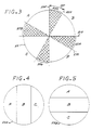
- FIG. 3 a quadrant-partitioned aperture for providing azimuth and elevation difference patterns is depicted in diagrammatic form.
- many radar systems employ two or more displaced radiating/receive elements (or groups of elements) so that each receives the signal from a point source at a slightly different phase.
- the received signals from each receive element (or group) are summed to form the array sum signal, and the received signal from one element (or group) is subtracted from the signal received on the other element (or group) to form a difference signal.
- the difference signal is a measure of the relative location of the target from the array boresight, since the difference signal will be nulled if the bore-sight is perfectly aligned on the target.
- Difference signals are typically provided in the azimuth and elevation directions.
- the azimuth difference signal indicates the angular offset of the boresight from the target along the azimuth axis, with the sign of the signal indicating the direction of the offset.
- the magnitude and sign of the elevation difference signal indicates the angular offset of the boresight from the target along the orthogonal elevation axis.
- the quadrant partitioning of the aperture 55 shown in FIG. 3 may be employed with system 50 to provide the azimuth and elevation difference signals.
- the radiative elements 60 of the array are adaptively associated with a respective one of the quadrants A, B, C, and D.
- axis 200 is aligned with the elevation axis
- orthogonal axis 210 is aligned with the azimuth axis.
- the elevation difference signal is provided by subtracting the combined signals received at the radiating elements in the C and D quadrants from the combined signals received at the elements in the A and B quadrants.
- the invention provides a means of arbitrarily assigning a particular radiating element to a particular quadrant of the array without requiring changes in hard wired connections or complex signal processing.
- the array controller is provided with attitude position data, e.g., from the aircraft inertial platform 98 in the case of an aircraft-mounted active array. This data may be used to direct the module control logic 174 to set the bi-phase phase shifters 166, 168 to the correct state for the particular roll angle, e.g., with the first difference component at the output of phase shifters 166 corresponding to the azimuth difference module signal, and the second difference signal at the output of phase shifter 168 corresponding to the elevation difference module signal.
- phase shifters 166 and 168 are set to the 0 degree phase shift state.
- phase shifter 166 azimuth difference
- phase shifter 168 elevation difference
- phase shifters 166 azimuth difference
- phase shifters 168 elevation difference
- the phase shifters 166 and 168 are both set to the 180 degree phase shift state.
- the quadrant positions of certain of the radiating elements are reassigned.
- the radiating elements located in the cross-hatched sector 222 nominally in the A quadrant for the case when the aircraft is aligned with the horizon, are reassigned to the B quadrant.
- the radiating elements in sector 224 nominally in sector D, are reassigned to the B quadrant.
- the radiating elements in sector 226, formerly in D quadrant, are reassigned to the C quadrant.
- the radiating elements in sector 228, formerly in quadrant C are reassigned to sector A.
- the reassignment of radiating elements requires only that the states of the phase shifters 166, 168 of the modules associated with the reassigned elements to be adjusted to the states described above for the radiating elements in the respective quadrants. With the array controller, this reassignment may be achieved very quickly. Thus, the difference pattern of the array may be electronically roll stabilized, without the need for mechanical roll gimbals or complex signal processing.
- FIGS. 4 and 5 shows circular apertures 55A and 55B partitioned into three separate receiving apertures A, B, C required in a number of applications such as low speed moving target tracking, negating cross-eyed jammers, resolving closely spaced (in azimuth) targets (FIG. 4), or reducing multipath interference and resolving closely spaced (in elevation) targets (FIG. 5).
- the shape and orientation of the A, B, C portions of the array can be varied at will with no hardware modifications, simply by altering the states of respective ones of the phase shifters 166, 168.
- An active array system has been described for providing an electronically roll-stabilized and partitioned receive aperture.
Landscapes
- Variable-Direction Aerials And Aerial Arrays (AREA)
- Radar Systems Or Details Thereof (AREA)
Claims (8)
- Aktives Anordnungs- bzw. Gruppensystem (50) zum Bereitstellen von elektronisch rollstabilisierten Gruppen-Differenzmustern, mit
einer Gruppe von beabstandeten Strahlungselementen, die eine Strahlungsapertur zum Empfangen elektromagnetischer Signale bilden,
einer Vielzahl erster Einrichtungen (166) zur Phasenverschiebung der empfangenen Signale,
einer Einrichtung (80B) zum Zusammenfassen bzw. Verknüpfen der phasenverschobenen Empfangssignale zur Bildung eines ersten Differenzkanal-Ausgangssignals (92), und
einer Einrichtung zur Rollstabilisierung des ersten Differenzkanal-Ausgangssignals (92),
dadurch gekennzeichnet,
daß mit jedem Strahlungselement (60) eines aus einer Vielzahl von aktiven Modulen gekoppelt ist, wobei jedes Modul eine aus einer Vielzahl erster Phasenverschiebungseinrichtungen (166) enthält, die das empfangene Signal selektiv um relative Phasenverschiebungen von im wesentlichen 0 Grad oder 180 Grad in Abhängigkeit von einem ersten Modul-Steuersignal zur Bildung eines ersten Moduls-Empfangssignals phasenverschiebt,
daß eine Einrichtung zum Bereitstellen von Lagepositionssignalen, die die relative Lageposition der Gruppe bezüglich einer Referenzposition repräsentieren, vorhanden ist, und daß die Roll-Stabilisierungseinrichtung
eine Steuereinrichtung (174) zum Anlegen jeweiliger erster Modul-Steuersignale an die Module durch adaptives Unterteilen der Apertur in rollstabilisierte Sektoren (222, 224, 226, 228) und durch adaptives Zuordnen jedes Strahlungselements zu einem jeweiligen der Sektoren in Abhängigkeit von den Lagesteuersignalen durch Steuerung des Zustands der ersten Phasenverschiebungseinrichtung (166) aufweist. - Aktives Gruppensystem nach Anspruch 1, bei dem das Modul weiterhin eine zweite Phasenverschiebungseinrichtung (168) zum selektiven Phasenverschieben des empfangenen Signals um relative Phasenverschiebungen von im wesentlichen 0 Grad oder 180 Grad zur Bildung eines zweiten Modul-Empfangssignals aufweist, bei dem das System ferner eine Einrichtung zum Zusammenfassen bzw. Verknüpfen der jeweiligen zweiten Modul-Empfangssignale zur Bildung eines zweiten Differenzkanal-Ausgangssignals (93) umfaßt, und bei dem die Steuereinrichtung weiterhin zum Anlegen jeweiliger zweiter Modul-Steuersignale an die Module zur Steuerung des Zustands der jeweiligen zweiten Phasenverschiebungseinrichtung zur Rollstabilisierung des zweiten Differenzkanal-Ausgangssignals ausgelegt ist.
- Aktives Gruppensystem nach Anspruch 2, bei dem die Referenzposition mit dem Azimut ausgerichtet ist und das erste Differenzkanal-Ausgangssignal (92) ein rollstabilisiertes Azimuth-Differenzsignal und das zweite Differenzkanal-Ausgangssignal (93) ein rollstabilisiertes Elevations-Differenzsignal repräsentieren.
- Aktives Gruppensystem nach Anspruch 2 oder Anspruch 3, bei dem die Steuereinrichtung die Gruppe in rollstabilisierte Quadrantensektoren unterteilt und für jeden der ersten und zweiten Differenzkanäle adaptiv jedes Strahlungselement zu einem bestimmten Quadranten (A, B, C, D) durch Steuern der Zustände des ersten und zweiten Phasenverschiebungseinrichtungen (166, 168) zuordnet.
- Aktives Anordnungs- bzw. Gruppensystem (50) mit,
einer Vielzahl von beabstandeten Strahlungselementen, die eine Systemanordnungs-Strahlungsapertur (55) zum Empfangen elektromagnetischer Signale bilden, und
einer Vielzahl von aktiven Verstärkern (156) zum Bereitstellen eines verstärkten Empfangssignals für das jeweilige Element,
gekennzeichnet durch
eine Vielzahl aktiver Module (150), die jeweils mit einem der Strahlungselemente (60) gekoppelt sind und von denen jedes einen der aktiven Verstärker, eine Leistungsaufteilungseinrichtung (164) zum Aufteilen der Leistung des verstärkten Signals in erste, zweite und dritte Empfangssignalkomponenten, von denen die erste Signalkomponente ein erstes Modul-Ausgangssignal bildet, sowie erste und zweite, zweite Zustände besitzende Phasenverschiebungseinrichtungen (166, 168) zum jeweiligen Verschieben der Phase der zweiten und der dritten Signalkomponenten um 0 Grad oder 180 Grad in Abhängigkeit von ersten und zweiten Steuersignalen zur Bildung zweiter und dritter Modul-Ausgangssignale aufweist,
ein erstes Summiernetzwerk (80C), das mit der Vielzahl von Modulen zur Summation der ersten Modul-Ausgangssignale zur Bildung eines Gruppen-Summensignals (91) gekoppelt ist,
ein zweites Summiernetzwerk (80B), das mit der Vielzahl von Modulen zur Summation der jeweiligen zweiten Modul-Ausgangssignale zur Bildung eines ersten Differnzsignals (92) gekoppelt ist,
ein drittes Summiernetzwerk (80D), das mit der Vielzahl von Modulen zur Summation der jeweiligen dritten Modul-Ausgangssignale zur Bildung eines zweiten Differenzsignals (93) gekoppelt ist, und
einen System-Prozessor, der die Strahlungsapertur adaptiv in drei unabhängige Empfangsaperturen unterteilt, jedes Strahlungselement adaptiv zu einer bestimmten der Empfangsaperturen durch Steuerung des Zustands des zwei Zustände besitzenden Phasenschieber (166, 168) zuordnet, und adaptiv die Apertur-Beziehung jedes Strahlungselements in Reaktion auf Lagepositionssignale dadurch umkonfiguriert, daß die zwei Zustände besitzenden Phasenschieber (166, 168) in einem zugeordneten Modul auf den geeigneten Zustand eingestellt werden, um die drei Aperturen rollzustabilisieren. - Gruppensystem nach Anspruch 5, bei dem der System-Prozessor eine Einrichtung zum Summieren der ersten und zweiten Differenzsignale und zum Dividieren der Summe durch zwei zur Bildung eines ersten Apertur-Empfangssignals aufweist.
- Gruppensystem nach Anspruch 5 oder 6, bei dem der System-Prozessor einer Einrichtung zum Subtrahieren des zweiten Differenzsignals vom Summensignal und zum Dividieren der Differenz durch 1/2 zur Bildung eines zweiten Apertur-Empfangssignals aufweist.
- Gruppensystem nach einem der Ansprüche 5 bis 7, bei dem der System-Prozessor eine Einrichtung zum Subtrahieren des zweiten Differenzsignals vom Summensignal und zum Dividieren des Differenzsignals durch 1/2 zur Bildung eines dritten Apertur-Empfangssignals aufweist.
Applications Claiming Priority (2)
| Application Number | Priority Date | Filing Date | Title |
|---|---|---|---|
| US07/044,638 US4882587A (en) | 1987-04-29 | 1987-04-29 | Electronically roll stabilized and reconfigurable active array system |
| US44638 | 1987-04-29 |
Publications (2)
| Publication Number | Publication Date |
|---|---|
| EP0313636A1 EP0313636A1 (de) | 1989-05-03 |
| EP0313636B1 true EP0313636B1 (de) | 1993-05-26 |
Family
ID=21933474
Family Applications (1)
| Application Number | Title | Priority Date | Filing Date |
|---|---|---|---|
| EP88904787A Expired - Lifetime EP0313636B1 (de) | 1987-04-29 | 1988-04-19 | Verfahren zur rollstabilisierung und verteilung von empfangsöffnungen einer phasengesteuerten antennengruppe |
Country Status (6)
| Country | Link |
|---|---|
| US (1) | US4882587A (de) |
| EP (1) | EP0313636B1 (de) |
| CA (1) | CA1290430C (de) |
| DE (1) | DE3881332T2 (de) |
| IL (1) | IL86198A (de) |
| WO (1) | WO1988008624A1 (de) |
Families Citing this family (13)
| Publication number | Priority date | Publication date | Assignee | Title |
|---|---|---|---|---|
| US4803490A (en) * | 1984-10-26 | 1989-02-07 | Itt Gilfillan, A Division Of Itt Corporation | Horizon stabilized antenna beam for shipboard radar |
| US5281974A (en) * | 1988-01-11 | 1994-01-25 | Nec Corporation | Antenna device capable of reducing a phase noise |
| JP2556934B2 (ja) * | 1990-11-30 | 1996-11-27 | 日本無線株式会社 | アンテナの揺動補償方式及び揺動補償型アンテナ装置 |
| US5469165A (en) * | 1993-12-23 | 1995-11-21 | Hughes Aircraft Company | Radar and electronic warfare systems employing continuous transverse stub array antennas |
| US5587714A (en) * | 1995-03-10 | 1996-12-24 | Space Systems/Loral, Inc. | Spacecraft antenna pointing error correction |
| US6005512A (en) * | 1998-06-16 | 1999-12-21 | Boeing North American, Inc. | Array antennas with low sum and difference pattern side lobes and method of producing same |
| US7327698B1 (en) | 1999-06-03 | 2008-02-05 | The Directv Group, Inc. | Method and system for providing satellite communications using on-orbit payload configuration and reconfiguration |
| DE19938862C1 (de) | 1999-08-17 | 2001-03-15 | Kathrein Werke Kg | Hochfrequenz-Phasenschieberbaugruppe |
| DE10104564C1 (de) | 2001-02-01 | 2002-09-19 | Kathrein Werke Kg | Steuerungsvorrichtung zum Einstellen eines unterschiedlichen Absenkwinkels insbesondere von zu einer Basisstation gehörenden Mobilfunkantennen sowie eine zugehörige Antenne und Verfahren zur Veränderung eines Absenkwinkels |
| US7843376B1 (en) * | 2006-12-27 | 2010-11-30 | Lockheed Martin Corporation | Cross-eye jamming detection and mitigation |
| EP2389731A4 (de) | 2009-01-26 | 2013-01-02 | Univ Drexel | Systeme und verfahren zur auswahl neukonfigurierbarer antennen in mimo-systemen |
| WO2012103855A2 (zh) * | 2012-04-20 | 2012-08-09 | 华为技术有限公司 | 天线及基站 |
| US10320517B2 (en) | 2017-06-05 | 2019-06-11 | J3 Technology LLC | Switched transmit antennas with no feedback for multipath reduction |
Family Cites Families (17)
| Publication number | Priority date | Publication date | Assignee | Title |
|---|---|---|---|---|
| US3202992A (en) * | 1962-05-28 | 1965-08-24 | Robert L Kent | Interferometer seeker |
| US3345631A (en) * | 1964-09-18 | 1967-10-03 | Texas Instruments Inc | Phased array radar antenna scan control |
| DE1498041A1 (de) * | 1965-04-07 | 1970-12-17 | Telefunken Patent | Verfahren zur raumfesten Stabilisierung eines Richtdiagramms |
| US3403401A (en) * | 1966-11-25 | 1968-09-24 | Texas Instruments Inc | Digital phase shift control for phased array radar |
| NO126499B (de) * | 1968-12-20 | 1973-02-12 | Smiths Industries Ltd | |
| US3719949A (en) * | 1969-12-31 | 1973-03-06 | Texas Instruments Inc | Antenna pattern roll stabilization |
| US3943523A (en) * | 1972-03-07 | 1976-03-09 | Raytheon Company | Airborne multi-mode radiating and receiving system |
| US3953857A (en) * | 1972-03-07 | 1976-04-27 | Jenks Frederic A | Airborne multi-mode radiating and receiving system |
| US3729742A (en) * | 1972-08-14 | 1973-04-24 | Us Navy | Simultaneous sum and difference pattern technique for circular array antennas |
| US3806924A (en) * | 1973-02-13 | 1974-04-23 | Us Navy | Platform motion compensating for airborne radars |
| US3940770A (en) * | 1974-04-24 | 1976-02-24 | Raytheon Company | Cylindrical array antenna with radial line power divider |
| US3938610A (en) * | 1975-02-10 | 1976-02-17 | Harman Eugene V | Automotive hood safety device |
| US3965475A (en) * | 1975-05-30 | 1976-06-22 | The United States Of America As Represented By The United States Administrator Of The National Aeronautics And Space Administration | Switchable beamwidth monopulse method and system |
| US4532519A (en) * | 1981-10-14 | 1985-07-30 | Rudish Ronald M | Phased array system to produce, steer and stabilize non-circularly-symmetric beams |
| US4607259A (en) * | 1984-10-25 | 1986-08-19 | At&T Bell Laboratories | Adaptive antenna for reducing multipath fades |
| EP0207511B1 (de) * | 1985-07-05 | 1991-07-24 | Siemens Aktiengesellschaft | Gruppenantenne mit elektronisch phasengesteuerter Strahlschwenkung |
| US4792805A (en) * | 1987-04-28 | 1988-12-20 | Hughes Aircraft Company | Multifunction active array |
-
1987
- 1987-04-29 US US07/044,638 patent/US4882587A/en not_active Expired - Lifetime
-
1988
- 1988-04-19 EP EP88904787A patent/EP0313636B1/de not_active Expired - Lifetime
- 1988-04-19 WO PCT/US1988/001230 patent/WO1988008624A1/en not_active Ceased
- 1988-04-19 DE DE8888904787T patent/DE3881332T2/de not_active Expired - Fee Related
- 1988-04-26 CA CA000565112A patent/CA1290430C/en not_active Expired - Fee Related
- 1988-04-27 IL IL86198A patent/IL86198A/xx not_active IP Right Cessation
Also Published As
| Publication number | Publication date |
|---|---|
| EP0313636A1 (de) | 1989-05-03 |
| WO1988008624A1 (en) | 1988-11-03 |
| CA1290430C (en) | 1991-10-08 |
| IL86198A0 (en) | 1988-11-15 |
| IL86198A (en) | 1991-12-15 |
| DE3881332T2 (de) | 1993-09-09 |
| US4882587A (en) | 1989-11-21 |
| DE3881332D1 (de) | 1993-07-01 |
Similar Documents
| Publication | Publication Date | Title |
|---|---|---|
| US4792805A (en) | Multifunction active array | |
| US5952965A (en) | Adaptive main beam nulling using array antenna auxiliary patterns | |
| US7463191B2 (en) | Antenna beam steering and tracking techniques | |
| US6771218B1 (en) | Electronically agile multi-beam antenna | |
| EP0313636B1 (de) | Verfahren zur rollstabilisierung und verteilung von empfangsöffnungen einer phasengesteuerten antennengruppe | |
| US8466829B1 (en) | Super-angular and range-resolution with phased array antenna and multifrequency dither | |
| US6549164B2 (en) | Distributed adaptive combining system for multiple aperture antennas including phased arrays | |
| US7009557B2 (en) | Interference rejection GPS antenna system | |
| US7248215B2 (en) | Beam architecture for improving angular resolution | |
| US4532519A (en) | Phased array system to produce, steer and stabilize non-circularly-symmetric beams | |
| EP1393404A2 (de) | Dynamische signalleitweglenkung für elektronisch abtastende antennensysteme | |
| US5771016A (en) | Phased array radar with simultaneous beam-steering and single-sideband modulation | |
| US6965343B1 (en) | System and method for antenna tracking | |
| US20060033659A1 (en) | Mobile satcom antenna discrimination enhancement | |
| US4450448A (en) | Apparatus and method for improving antenna sidelobe cancellation | |
| US7450068B2 (en) | Phased array antenna beam tracking with difference patterns | |
| US6906665B1 (en) | Cluster beam-forming system and method | |
| US10910709B1 (en) | Control architecture for electronically scanned array | |
| EP0621654A2 (de) | Aktive Gruppenantenne | |
| US5486831A (en) | Multi-mode missile seeker with adjunct sensor blocking an electronically scanned radio frequency aperture using an off-boresight direction finding process | |
| US7315279B1 (en) | Antenna system for producing variable-size beams | |
| US5128682A (en) | Directional transmit/receive system for electromagnetic radiation with reduced switching | |
| JP2001007640A (ja) | 多機能アンテナ装置 | |
| US7042393B1 (en) | Thinned array antenna system | |
| US3836929A (en) | Low angle radio direction finding |
Legal Events
| Date | Code | Title | Description |
|---|---|---|---|
| PUAI | Public reference made under article 153(3) epc to a published international application that has entered the european phase |
Free format text: ORIGINAL CODE: 0009012 |
|
| 17P | Request for examination filed |
Effective date: 19890120 |
|
| AK | Designated contracting states |
Kind code of ref document: A1 Designated state(s): DE FR GB IT SE |
|
| 17Q | First examination report despatched |
Effective date: 19910322 |
|
| GRAA | (expected) grant |
Free format text: ORIGINAL CODE: 0009210 |
|
| AK | Designated contracting states |
Kind code of ref document: B1 Designated state(s): DE FR GB IT SE |
|
| REF | Corresponds to: |
Ref document number: 3881332 Country of ref document: DE Date of ref document: 19930701 |
|
| ET | Fr: translation filed | ||
| ITF | It: translation for a ep patent filed | ||
| PLBE | No opposition filed within time limit |
Free format text: ORIGINAL CODE: 0009261 |
|
| STAA | Information on the status of an ep patent application or granted ep patent |
Free format text: STATUS: NO OPPOSITION FILED WITHIN TIME LIMIT |
|
| 26N | No opposition filed | ||
| EAL | Se: european patent in force in sweden |
Ref document number: 88904787.4 |
|
| PGFP | Annual fee paid to national office [announced via postgrant information from national office to epo] |
Ref country code: FR Payment date: 19960311 Year of fee payment: 9 |
|
| PGFP | Annual fee paid to national office [announced via postgrant information from national office to epo] |
Ref country code: SE Payment date: 19960318 Year of fee payment: 9 |
|
| PGFP | Annual fee paid to national office [announced via postgrant information from national office to epo] |
Ref country code: GB Payment date: 19960319 Year of fee payment: 9 |
|
| PGFP | Annual fee paid to national office [announced via postgrant information from national office to epo] |
Ref country code: DE Payment date: 19960325 Year of fee payment: 9 |
|
| PG25 | Lapsed in a contracting state [announced via postgrant information from national office to epo] |
Ref country code: GB Effective date: 19970419 |
|
| PG25 | Lapsed in a contracting state [announced via postgrant information from national office to epo] |
Ref country code: SE Effective date: 19970420 |
|
| GBPC | Gb: european patent ceased through non-payment of renewal fee |
Effective date: 19970419 |
|
| PG25 | Lapsed in a contracting state [announced via postgrant information from national office to epo] |
Ref country code: FR Free format text: LAPSE BECAUSE OF NON-PAYMENT OF DUE FEES Effective date: 19971231 |
|
| PG25 | Lapsed in a contracting state [announced via postgrant information from national office to epo] |
Ref country code: DE Free format text: LAPSE BECAUSE OF NON-PAYMENT OF DUE FEES Effective date: 19980101 |
|
| EUG | Se: european patent has lapsed |
Ref document number: 88904787.4 |
|
| REG | Reference to a national code |
Ref country code: FR Ref legal event code: ST |
|
| PG25 | Lapsed in a contracting state [announced via postgrant information from national office to epo] |
Ref country code: IT Free format text: LAPSE BECAUSE OF NON-PAYMENT OF DUE FEES Effective date: 20050419 |