EP0312464B1 - Elektrische Maschine insbesondere mit radialen Luftspalten - Google Patents
Elektrische Maschine insbesondere mit radialen Luftspalten Download PDFInfo
- Publication number
- EP0312464B1 EP0312464B1 EP88402609A EP88402609A EP0312464B1 EP 0312464 B1 EP0312464 B1 EP 0312464B1 EP 88402609 A EP88402609 A EP 88402609A EP 88402609 A EP88402609 A EP 88402609A EP 0312464 B1 EP0312464 B1 EP 0312464B1
- Authority
- EP
- European Patent Office
- Prior art keywords
- machine according
- teeth
- movable element
- magnets
- movable
- Prior art date
- Legal status (The legal status is an assumption and is not a legal conclusion. Google has not performed a legal analysis and makes no representation as to the accuracy of the status listed.)
- Expired - Lifetime
Links
Images

Classifications
-
- H—ELECTRICITY
- H02—GENERATION; CONVERSION OR DISTRIBUTION OF ELECTRIC POWER
- H02K—DYNAMO-ELECTRIC MACHINES
- H02K33/00—Motors with reciprocating, oscillating or vibrating magnet, armature or coil system
- H02K33/02—Motors with reciprocating, oscillating or vibrating magnet, armature or coil system with armatures moved one way by energisation of a single coil system and returned by mechanical force, e.g. by springs
- H02K33/04—Motors with reciprocating, oscillating or vibrating magnet, armature or coil system with armatures moved one way by energisation of a single coil system and returned by mechanical force, e.g. by springs wherein the frequency of operation is determined by the frequency of uninterrupted AC energisation
- H02K33/06—Motors with reciprocating, oscillating or vibrating magnet, armature or coil system with armatures moved one way by energisation of a single coil system and returned by mechanical force, e.g. by springs wherein the frequency of operation is determined by the frequency of uninterrupted AC energisation with polarised armatures
-
- H—ELECTRICITY
- H02—GENERATION; CONVERSION OR DISTRIBUTION OF ELECTRIC POWER
- H02K—DYNAMO-ELECTRIC MACHINES
- H02K21/00—Synchronous motors having permanent magnets; Synchronous generators having permanent magnets
- H02K21/38—Synchronous motors having permanent magnets; Synchronous generators having permanent magnets with rotating flux distributors, and armatures and magnets both stationary
Definitions
- the invention relates to electrical machines (motors or alternators) consisting of a rotor coaxial with a stator and free to rotate relative to the latter about a common axis, this rotor and this stator being provided with opposite magnetic poles. and inductor means (windings, exciters or receiver-alternators) and permanent magnets being arranged so as to establish a correlation between the relative rotation rotor / stator and the current flowing in the inductor means.
- a motor with a discoid rotor and permanent magnets with axial magnetization is already known from the French document FR-2,588,132; the permanent magnets are there at least partly carried by the rotor and the inductor means there are annular coils carried by the stator and coaxial with it, and arranged radially outside the magnetic poles.
- the document EP-A-0.072.774 (GÜTTINGER) describes a single-phase motor, small and inexpensive, but comprising many elements, including a device for damping and phase shifting of flux engaged in a hollow between two polar rings circumferentially offset, at least on one side of the coil of this motor.
- These crowns are pieces of soft iron curved so as to present axial teeth; similarly, soft iron stator poles are arranged longitudinally on the internal face of a single magnet. The shape and thickness poles does not allow the passage of large flows.
- the invention relates to an electric machine with very high performance, easy and inexpensive to manufacture, and having in particular, in engine speed, a large mass torque and low inertia with low losses by JOULE effect, while ensuring, if the machine is polyphase, a good magnetic decoupling of the phases of such a motor.
- N elementary machines can thus constitute, in particular, an electric stepping motor, a brushless motor with electronic commutation or an alternator with N phases.
- the invention applies very particularly well to robotics, to high-performance electro-mechanical servos, to stepping motors and for example to motors with limited clearance for the control of servovalve distributors.
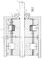
- FIG. 1 schematically represents an electrical machine with several electrical phases which conventionally comprises a fixed structure 1 forming a stator and a movable assembly 2 forming a rotor movable in rotation relative to the stator relative to an axis Z-Z.
- the stator 1 mainly comprises a casing 3 internally carrying stator elements 4 which will be detailed below, while the rotor 2 mainly comprises a central shaft 5 guided in rotation by bearings 6 of any suitable type and held axially relative to the stator by conventional retaining elements not shown.
- This central shaft 5 likewise carries rotor elements 7 which will be detailed later.
- This machine further comprises inductive members including windings 8 connected by means not shown to external electrical equipment of any suitable known type.
- the rotor is rotated relative to the stator under the action of currents flowing in the windings (electric motor mode); conversely, electric current is generated in the windings 8 due to a relative rotation of the rotor relative to the stator.
- the electric machine of FIG. 1 is modular in the sense that it comprises as many 4 + 7 modules as there are electric phases N in this machine, these identical modules being such that the rotors are offset relative to the stators mechanically. from an angle ⁇ / n from one phase to the next.
- Figure 1 appear two modules arranged axially side by side, it being specified that these modules are magnetically decoupled as will appear below. In fact, the module on the left is shown more schematically than that on the right.
- the stator element 4 of each module comprises a magnetic carcass provided with two magnetic crowns 9 and 10 in radial projection and with permanent magnetization, with a radial magnetization component which varies periodically along the circumference of these crowns according to a predetermined angular period so as to form an annular succession of P pairs of alternating radial magnetic poles NS.
- the radial magnetization components are in opposite directions at any pair of axially opposite points of these crowns with permanent magnetization.
- each module it comprises a magnetic carcass formed by two discontinuous magnetic rings connected by a magnetic sleeve 13 linked to the shaft 5 and each formed from a plurality of D polar teeth 11 and 12 arranged radially projecting opposite crowns 9 and 10 with permanent magnetization, , with which they define air gaps of thickness e .
- the poles are magnetized transversely to the paths T of the teeth.
- Each module comprises an inductive winding 8, annular, mounted on the stator coaxially with the latter being disposed axially, partly between the stator rings 9 and 10 with permanent magnetization, and partly between the discontinuous rings of polar teeth 11 and 12
- This winding is connected in a known manner to an alternating current source, not shown.
- the magnetic flux circulates around the coil 8 through permanent magnets and air gaps, here disposed axially on either side of this coil.
- the stator can wear a single magnetized crown 9 or 10 facing a single series of teeth, the other crown being replaced by magnetic material, the spaces existing between the associated polar teeth being moreover filled.
- FIG. 13 An example is given in FIG. 13 where elements similar to those of FIGS. 1 to 5 have references which are deduced from the references of these figures by adding the number 80.
- This figure illustrates a rotary motor which, by phase, comprises a single magnetized crown 90 and a single series of teeth 92, while the other air gap is continuous with a constant thickness between stator 81 and rotor 87 elements of soft magnetic material allowing the return of the flux.
- This air gap here has the diameter of the hub of the rotor element 87 which is thus very easy to manufacture, since it has only one crown projecting radially.
- This embodiment easy to assemble and to carry out, applies particularly well to a compact two-phase machine.
- An axial space d exists between the magnetic carcasses of two neighboring modules, thanks to which good magnetic decoupling of these modules is ensured.
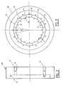
- stator carcass 4 of each module is composed of two similar half-carcasses 4A and 4B secured back to back by any appropriate means.
- Each half-carcass has the shape of a torus projecting radially inwardly a magnetic ring 14 bordering a half-groove 15 to receive the coil 8 and intended to carry, on its edge facing radially towards the axis, the crown 9 or 10 above.
- the magnetic crown 10 the radial dimension or thickness of which is denoted E, is formed of an annular series of 2F permanent magnets 16 and 16 ′ with radial magnetization in the form of tiles, with alternating magnetization directions.
- the circumferential magnetization component of these magnets is negligible.
- the magnetized rings 9 or 10 are formed of magnetic poles having a magnetization of substantially constant modulus, with a non-zero circumferential magnetization component By, which varies periodically with the same period as Bx but with a phase shift of ⁇ / 2.
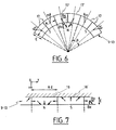
- the crown considered is formed of pairs of magnetic tiles 17 and 17 '; the angle formed by the magnetization vector at each point of a tile with a radius connecting this point to the axis has a given value between 0 ° and 45 °, to be optimized as a function of the number P of pairs of poles.
- a regular assembly of pairs of poles is thus obtained, each pole of which comprises two magnetized tiles 17 or 17 'arranged head to tail and occupying an angular sector ⁇ equal to ⁇ / p corresponding to an arc length ⁇ .
- These may for example be samarium-cobalt magnets of the type sold by SEIKO EPSON CORPORATION under the references SAM or SAMLET.
- the magnetic ring 9 or 10 is composed of magnetic tiles 18 and 18 'whose radial components Bx and circumferential By of magnetization vary approximately sinusoidally, with an offset of ⁇ / 2.
- Such a type of magnetization can be obtained with the magnets of the above-mentioned type marked SAM 5 or SAMLET 3 or even magnets based on iron and rare earths as sold by GENERAL MOTORS under the name MAGNEQUENCH.
- This carcass 4 can be made of soft magnetic material (agglomerated iron powder, or association of laminated sheet metal or even molded ferrite). The choice of material depends of course on the intensity of the flux which must circulate in the stator for each phase.
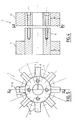
- This element is in two asymmetrical parts, a part comprising the discontinuous crown of teeth 11 and the sleeve 13 and a part carrying the discontinuous crown of teeth 12.
- These polar teeth regularly distributed from the angular point of view are identical here, with a radial dimension h called height and a circumferential dimension l called width. In fact, the geometric shape of the teeth is quite critical.
- These parts 11 + 13 and 12 are secured to each other by any appropriate means, here screws which penetrate into the sleeve 13 and whose heads are housed in the part carrying the teeth 12.
- These parts are made of a soft magnetic material, agglomerated iron powder or a combination of laminated sheets or molded ferrite.
- the number D of the teeth of each crown is here equal to the number P of pairs of poles, that is to say 8 in the example considered.
- the teeth of the rotor and the polarities of the magnets of the two half-carcasses 4A and 4B are positioned in such a way that the magnetic potential of the magnets facing the poles of the rotor is added and that the magnetic flux thus created by the magnets through the coil 8 varies almost sinusoidally as a function of the angular position of the rotor relative to the stator.
- a width l of the rotor tooth of between 0.25 and 0.35 of the pole pitch 2 ⁇ makes it possible to obtain a flux through the quasi-sinusoidal coil.
- the ideal would be to obtain an orientation of the magnetization of the "sinusoidal" magnets (in accordance with FIG. 7) which gives a torque without current comprising only harmonic 2 and a flux picked up by the coil almost without harmonic distortion and of high value.
- the height of the rotor tooth h is at least equal to ⁇ .
- the gap e between the magnets and the rotor teeth will be reduced to the minimum compatible with the design constraints mechanical. We will take e ⁇ 0.15 mm if possible. The unfavorable influence of the air gap is all the more notable when the thickness of the magnets is low (machine of small size or with a large number of pairs of poles).
- the parts made of soft magnetic material can be manufactured by molding of material based on iron powder of the type COROVAC EF 606 or in ferrite for machines of lower performance but more economical, or also by association of laminated sheets.
- the permanent magnets can be produced in a single piece by molding and multipolar magnetization, or by bonding of magnetized tiles on the stator carcasses.
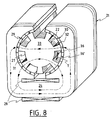
- FIGS 8 to 12 show alternative embodiments of an electric machine phase also having the advantages of the invention.
- FIG. 8 in which elements similar to those of FIGS. 1 to 5 bear reference numbers deduced therefrom after addition of the number 20, thus presents a motor phase in which the magnetic fluxes close in transverse planes through of disjointed semi-annular series 29 and 30 formed by magnets 36 and 36 ′ with radial magnetization.
- These series of magnets form two curved bars determining a cylindrical conduit in which is located the rotor 27 comprising at all times equal numbers of teeth 31-32 opposite one and the other of these bars.
- These teeth are arranged so that to each tooth facing a North (or South) pole of one of the bars corresponds a tooth facing a South (or North) pole of the other bar, this which allows an approximately radial circulation of the magnetic flux through the rotor.
- These bars 29 and 30 are connected through a body 24 made of soft magnetic material engaged inside an inductive coil 28 arranged in an axial plane.
- the rotor 22 and the stator 21 are laminated perpendicular to the axis of the motor.
- the electric motor of FIGS. 9 to 11 on which the elements similar to those of FIGS. 1 to 5 bear references which deduced therefrom by addition of the number 40 have magnetized crowns 49 and 50 with axial magnetization, facing axially from a crown of teeth 51-52 which are axially traversed by the magnetic fluxes and each of which is both facing d '' a South pole of one of the crowns and opposite a North pole of the other crown.
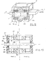
- linear motor of Figure 12 differs from the rotary motor of Figure 1 by the fact that the magnetized crowns 9 and 10 are replaced by longitudinal bars 69A-69B and 70A and 70B.
- the polar teeth are here constituted, on either side of a horizontal plane P containing the path T of the movable element in translation 62 sliding on bearings 79, of two pairs 71A and 71B, and 72A and 72B .
- This motor here admits a horizontal plane of symmetry but it must be understood that the teeth and the magnets of the upper (or lower) part can be eliminated: the elements A and the elements B are redundant.
- the polar teeth are of massive shape, which makes them compatible with the flux levels of the permanent magnets opposite (the latter are chosen from high performance materials): their section, which is substantially constant, allows the circulation of the flux of coils and magnets without saturation.
- teeth have the same angular setting with respect to the poles of the stator to an integer multiple of ⁇ / p near (if p is the number of pairs of poles).
- the alternating poles play the same role with respect to all the polar teeth opposite the same bar.
Landscapes
- Engineering & Computer Science (AREA)
- Power Engineering (AREA)
- Permanent Field Magnets Of Synchronous Machinery (AREA)
- Permanent Magnet Type Synchronous Machine (AREA)
- Linear Motors (AREA)
Claims (20)
- Elektrische Maschine für mindestens eine Phase, mit einem beweglichen Körper, der einen Freiheitsgrad bezüglich eines feststehenden Körpers zuläßt, dadurch gekennzeichnet, daß sie für jede Phase umfaßt:- ein bewegliches Element (2, 22, 42, 62) aus weichmagnetischem Material, das mit dem beweglichen Körper verbunden ist und zumindest eine Vielzahl von identischen Polzähnen (11, 12; 31, 32; 51, 52; 71, 72) trägt, die gegen den festen Körper vorspringend und senkrecht zu ihren Bahnen (T) angeordnet sind, wobei alle Zähne dieses beweglichen Elementes eine Symmetrieebene zulassen, die senkrecht zu ihren Bahnen verläuft,- ein feststehendes Element (1, 21, 41, 61) aus weichmagnetischem Material, das mit dem feststehenden Körper verbunden ist und den Polzähnen gegenüberliegend, mit denen es einen konstanten, diskontinuierlichen Spalt (e) festlegt, wenigstens einen Stabmagnet (9, 10; 29, 30; 49, 50; 69, 70) mit periodischer Dauermagnetisierung trägt, der über einen magnetischen Körper (4, 24, 44, 64) befestigt ist und in Richtung der Vielzahl der Zähne sowie senkrecht zum Spalt eine Magnetisierungskomponente aufweist, die längs des Stabes derart periodisch gemäß einer vorgegebenen Winkelperiode variiert, daß im Verhältnis von einem Polpaar pro Polzahn Wechselpole festgelegt werden,- sowie eine einzige induktive Spule (8, 28, 48, 68), die einen der magnetischen Körper (4, 24, 44, 64; 13, 33, 53, 73) des feststehenden und des beweglichen Elementes umgibt,wodurch sich Feldlinien quer durch diese Körper schließen können, welche die Polzähne und den besagten konstanten Spalt, den dauermagnetischen Stab sowie einen zweiten, zwischen dem feststehenden und dem beweglichen Element festgelegten Spalt durchlaufen.
- Maschine nach Anspruch 1, dadurch gekennzeichnet, daß das feststehende Element (1, 21, 41, 61) aus weichmagnetischem Material gegenüber den Polzähnen, mit denen es die zwei Spalte festlegt, zwei Stabmagnete mit Dauermagnetisierung trägt, die durch den magnetischen Körper verbunden sind, wobei sich die Vielzahl der Polzähne des beweglichen Elementes zu jedem Augenblick in wenigstens zwei Reihen (11, 12; 31, 32; 51, 52; 71, 72) mit derselben Anzahl an Zähnen aufgliedert, die durch einen magnetischen Körper (13, 33, 53, 73) so verbunden sind, daß jedem Zahn einer Reihe, der einem Pol eines Stabes gegenüberliegt, ein Zahn der anderen Reihe entspricht, der einem entgegengesetzten Pol des anderen Stabes gegenüberliegt.
- Maschine nach Anspruch 2, dadurch gekennzeichnet, daß die Stabmagnete mit Dauermagnetisierung so gebogen sind, daß sie zumindest Teilkränze ausbilden, wobei das bewegliche Element (2, 22, 42) in bezug auf das feststehende Element (1, 21, 41) frei drehbar ist.
- Maschine nach Anspruch 3, dadurch gekennzeichnet, daß die Stabmagnete mit Dauermagnetisierung (9, 10; 49, 50) aus axial versetzten Kränzen gebildet sind, wobei die Linien des Magnetfeldes sich in Axialebenen schließen und die induktive Spule koaxial zum beweglichen Element liegt.
- Maschine nach Anspruch 4, dadurch gekennzeichnet, daß diese Kränze mit Dauermagnetisierung (9, 10) radial gegenüber den Zahnreihen (11, 12) liegen und eine radiale Magnetisierung aufweisen.
- Maschine nach Anspruch 4, dadurch gekennzeichnet, daß diese Kränze mit Dauermagnetisierung (49, 50) axial gegenüber zusammengebauten Zahnreihen (51-52) liegen, wobei diese Kränze eine axiale Magnetisierung aufweisen.
- Maschine nach Anspruch 3, dadurch gekennzeichnet, daß diese Stabmagnete mit Dauermagnetisierung (29, 30) aus zwei einander radial gegenüberliegenden Halbkränzen gebildet sind, wobei die Linien des Magnetfeldes sich in querliegenden Ebenen schließen und die induktive Spule in einer Axialebene angeordnet ist.
- Maschine nach Anspruch 7, dadurch gekennzeichnet, daß das feststehende und das bewegliche Element quer zur Rotationsachse des beweglichen Elementes geblecht sind.
- Maschine nach einem der vorhergehenden Ansprüche 3 bis 8, dadurch gekennzeichnet, daß das bewegliche Element im Inneren des feststehenden Elementes angeordnet ist.
- Maschine nach Anspruch 1 oder nach Anspruch 2, dadurch gekennzeichnet, daß das bewegliche Element (62) in bezug auf das feststehende Element querbeweglich angeordnet ist, wobei die Stabmagnete (69, 70) parallel zur Bahn dieses beweglichen Elementes verlaufen.
- Maschine nach Anspruch 10, dadurch gekennzeichnet, daß sie Stäbe und Zahnreihen beidseits einer parallel zur Bahn dieses beweglichen Elementes verlaufenden Symmetrieebene aufweist.
- Maschine nach Anspruch 10 oder nach Anspruch 11, dadurch gekennzeichnet, daß das feststehende und das bewegliche Element senkrecht zur Bahn des beweglichen Elementes geblecht sind.
- Maschine nach Anspruch 1, dadurch gekennzeichnet, daß das bewegliche Element eine einzige Zahnreihe pro Phase aufweist, wobei der besagte zweite Spalt kontinuierlich ausgebildet und von konstanter Dicke ist.
- Maschine nach einem der Ansprüche 1 bis 13, dadurch gekennzeichnet, daß die Stabmagnete aus Magneten (16, 16') mit wechselnder Polarität gebildet sind.
- Maschine nach einem der Ansprüche 1 bis 14, dadurch gekennzeichnet, daß jeder Stab mit Dauermagnetisierung (9, 10) aus Dauermagneten (16, 16') gebildet ist, die in Längsrichtung eine vernachlässigbare Magnetisierungskomponente (By) aufweisen.
- Maschine nach einem der Ansprüche 1 bis 14, dadurch gekennzeichnet, daß jeder Stab mit Dauermagnetisierung (9, 10, 17, 17'; 18, 18') entlang seiner Länge eine von Null verschiedene Magnetisierungskomponente (By) in Längsrichtung aufweist, die periodisch mit derselben Periode wie die Haupt-Magnetisierungskomponente in Querrichtung, aber mit einer Phasenverschiebung von π/2, variiert.
- Maschine nach Anspruch 16, dadurch gekennzeichnet, daß jeder Stab aus Magneten (17, 17') gebildet ist, deren Magnetisierungsvektor in jedem Punkt einen konstanten Winkel (α), abgesehen vom Vorzeichen, mit einer durch diesen Punkt verlaufenden Normalen bildet und einen im wesentlichen konstanten Modul aufweist.
- Maschine nach Anspruch 16, dadurch gekennzeichnet, daß jeder Kranz längs eines Umfanges eine Dauermagnetisierung mit konstantem Modul aufweist, bei der die Radial- und die Umfangskomponente näherungsweise sinusförmig variieren.
- Maschine nach einem der Ansprüche 1 bis 18, dadurch gekennzeichnet, daß ein Axialspalt (d) zwischen zwei benachbarten Stator- oder Rotorelementen, die an unterschiedliche elektrische Phasen angeschlossen sind, ausgebildet ist.
- Maschine nach einem der Ansprüche 1 bis 19, dadurch gekennzeichnet, daß die Polzähne (11, 12) des beweglichen Elementes eine Höhe (h) aufweisen, die wenigstens gleich der Länge (τ) jedes Pols des gegenüberliegenden Stabmagneten (9, 10) ist, während ihre Breite (1) im Bereich von 0,25 bis 0,35 der Länge (2 τ ) jedes Polpaares liegt, wobei die radiale Dicke (E) jedes Stabmagneten (9, 10) im Bereich von 1/3 bis 1/6 der Länge (2τ) jedes Polpaares liegt.
Applications Claiming Priority (2)
| Application Number | Priority Date | Filing Date | Title |
|---|---|---|---|
| FR8714312 | 1987-10-16 | ||
| FR8714312A FR2622066B1 (fr) | 1987-10-16 | 1987-10-16 | Machine electrique a entrefers radiaux |
Publications (2)
| Publication Number | Publication Date |
|---|---|
| EP0312464A1 EP0312464A1 (de) | 1989-04-19 |
| EP0312464B1 true EP0312464B1 (de) | 1993-04-14 |
Family
ID=9355892
Family Applications (1)
| Application Number | Title | Priority Date | Filing Date |
|---|---|---|---|
| EP88402609A Expired - Lifetime EP0312464B1 (de) | 1987-10-16 | 1988-10-14 | Elektrische Maschine insbesondere mit radialen Luftspalten |
Country Status (5)
| Country | Link |
|---|---|
| US (1) | US4933585A (de) |
| EP (1) | EP0312464B1 (de) |
| DE (1) | DE3880255T2 (de) |
| ES (1) | ES2039671T3 (de) |
| FR (1) | FR2622066B1 (de) |
Families Citing this family (11)
| Publication number | Priority date | Publication date | Assignee | Title |
|---|---|---|---|---|
| FR2659734B1 (fr) * | 1990-03-14 | 1992-07-03 | Aerospatiale | Systeme pour le pilotage d'un missile au moyen de jets gazeux lateraux. |
| FR2659733B1 (fr) * | 1990-03-14 | 1994-07-01 | Aerospatiale | Systeme pour le pilotage d'un missile au moyen de tuyeres laterales. |
| FR2692982B1 (fr) * | 1992-04-24 | 1997-01-17 | Aerospatiale | Dispositif rotor/stator de modulation de tension, notamment pour moteur electrique sans balais. |
| US5590003A (en) * | 1995-03-08 | 1996-12-31 | Seagate Technology, Inc. | Hydrodynamic spindle motor having distributed windings |
| US6452300B1 (en) * | 1998-12-30 | 2002-09-17 | General Electric Company | Laminated stator yokes |
| AU2779800A (en) | 1999-04-16 | 2000-10-19 | Newage International Limited | An alternating current machine |
| JP4340415B2 (ja) * | 2002-02-15 | 2009-10-07 | 日本電産サンキョー株式会社 | ステッピングモータ |
| DE102005019112A1 (de) * | 2005-04-25 | 2006-10-26 | Siemens Ag | Kombinationsantrieb mit Hybridreluktanzmotor |
| DE102007028347A1 (de) * | 2006-12-19 | 2008-06-26 | Robert Bosch Gmbh | Elektrische Maschine |
| US20090051314A1 (en) * | 2007-08-21 | 2009-02-26 | Puthalath Koroth Raghuprasad | Self-powered magnetic generator |
| FR2970742B1 (fr) | 2011-01-20 | 2016-05-20 | Mbda France | Dispositif pour commander le passage d'un jet gazeux dans une tuyere d'engin volant, et engin volant comportant de tels dispositifs |
Family Cites Families (8)
| Publication number | Priority date | Publication date | Assignee | Title |
|---|---|---|---|---|
| US3469133A (en) * | 1965-10-13 | 1969-09-23 | Georges Stcherbatcheff | Electric motor with a bridge-type magnetic circuit |
| CH521045A (fr) * | 1968-03-22 | 1972-03-31 | Rech S En Matiere De Micro Mot | Moteur électrique destiné à être utilisé dans des applications ne relevant pas du domaine de la technique de la mesure du temps |
| FR2362516A1 (fr) * | 1975-08-22 | 1978-03-17 | Tokai Rika Co Ltd | Micromoteur electrique |
| US4088909A (en) * | 1977-02-18 | 1978-05-09 | Kanto Seiki Company, Limited | Stepping motor for timekeeping mechanism |
| US4224544A (en) * | 1978-10-05 | 1980-09-23 | Mckinnon Eugene T | Fan motor having reversible rotor |
| DE3001095A1 (de) * | 1980-01-14 | 1981-07-16 | Herbert Prof. Dr.-Ing. 3300 Braunschweig Weh | Elektrische maschine mit zweifacher erregung zur wechselmagnetisierung und ringwicklung |
| CS213928B1 (en) * | 1980-02-15 | 1982-04-09 | Vaclav Landa | Method of manufacturing anisotropic permanent magnets |
| EP0072774B1 (de) * | 1981-08-19 | 1985-09-11 | Sodeco-Saia Sa | Synchronmotor |
-
1987
- 1987-10-16 FR FR8714312A patent/FR2622066B1/fr not_active Expired - Lifetime
-
1988
- 1988-10-14 ES ES198888402609T patent/ES2039671T3/es not_active Expired - Lifetime
- 1988-10-14 EP EP88402609A patent/EP0312464B1/de not_active Expired - Lifetime
- 1988-10-14 DE DE88402609T patent/DE3880255T2/de not_active Expired - Fee Related
- 1988-10-17 US US07/258,639 patent/US4933585A/en not_active Expired - Lifetime
Also Published As
| Publication number | Publication date |
|---|---|
| DE3880255D1 (de) | 1993-05-19 |
| EP0312464A1 (de) | 1989-04-19 |
| FR2622066A1 (fr) | 1989-04-21 |
| US4933585A (en) | 1990-06-12 |
| DE3880255T2 (de) | 1993-11-25 |
| FR2622066B1 (fr) | 1995-08-25 |
| ES2039671T3 (es) | 1993-10-01 |
Similar Documents
| Publication | Publication Date | Title |
|---|---|---|
| EP0158935B1 (de) | Elekrodynamische Verniermaschine | |
| EP0811269B1 (de) | Zweiphasenmotor,insbesondere für zeitmessgerät oder zum antrieb eines zeigers einer anzeige | |
| FR2688105A1 (fr) | Actionneur rotatif electromagnetique monophase de course entre 60 et 120 degres. | |
| EP0889576B1 (de) | Linearmotor | |
| EP0151159A1 (de) | Mehrphasiger motor mit einem magnetizierten, pro fläche n/2 polpaare aufweisenden läufer | |
| EP0949747A1 (de) | Mehrphasenmotor, insbesondere zum antrieb eines zeigers einer anzeige | |
| FR2472866A1 (fr) | Moteur pas a pas electrique | |
| EP0942510A1 (de) | Elektrische Maschine mit Doppelerregung, insbesondere Wechselstromgenerator für ein Kraftfahrzeug | |
| WO1983002042A1 (fr) | Moteur pas a pas electrique | |
| EP0312464B1 (de) | Elektrische Maschine insbesondere mit radialen Luftspalten | |
| CH653189A5 (fr) | Moteur pas a pas electrique. | |
| EP0707374B1 (de) | Einphasigen Hybridbetätiger mit Flussschaltung | |
| CH659744A5 (fr) | Transducteur electromecanique. | |
| EP0547534B1 (de) | Elektromagnetischer Wandler mit einem vielpoligen Dauermagnet | |
| EP0816701A1 (de) | In Längs- und Querrichtung aktives Magnetlager | |
| EP0378596B1 (de) | Zwei- oder mehrphasiger elektrischer synchronmotor mit einem scheibenförmigen läufer | |
| FR2618616A1 (fr) | Machine electrique a couple d'entrainement et/ou de positionnement eleve | |
| EP3120445B1 (de) | Hybridelektrischemaschine | |
| EP0321332B1 (de) | Elektrischer Motor mit hohem Wirkungsgrad und schwacher Momentschwingung | |
| FR3099971A1 (fr) | Système de vis-écrou magnétiques | |
| FR3086118A1 (fr) | Machine electrique tournante munie d'un rotor a masse reduite | |
| CH622914A5 (en) | Electric motor | |
| FR2716046A1 (fr) | Machine électrique tournante à bobinage global. | |
| WO2026017765A1 (fr) | Rotor pour moteur électrique équipé de flasques d'extrémité intégrant des plasto-aimants | |
| FR3106449A1 (fr) | Machine électrique à flux transverse à aimants permanents au stator |
Legal Events
| Date | Code | Title | Description |
|---|---|---|---|
| PUAI | Public reference made under article 153(3) epc to a published international application that has entered the european phase |
Free format text: ORIGINAL CODE: 0009012 |
|
| AK | Designated contracting states |
Kind code of ref document: A1 Designated state(s): BE CH DE ES FR GB GR IT LI LU NL SE |
|
| 17P | Request for examination filed |
Effective date: 19890710 |
|
| 17Q | First examination report despatched |
Effective date: 19910522 |
|
| GRAA | (expected) grant |
Free format text: ORIGINAL CODE: 0009210 |
|
| AK | Designated contracting states |
Kind code of ref document: B1 Designated state(s): BE CH DE ES FR GB GR IT LI LU NL SE |
|
| REF | Corresponds to: |
Ref document number: 3880255 Country of ref document: DE Date of ref document: 19930519 |
|
| GBT | Gb: translation of ep patent filed (gb section 77(6)(a)/1977) |
Effective date: 19930526 |
|
| ITF | It: translation for a ep patent filed | ||
| REG | Reference to a national code |
Ref country code: GR Ref legal event code: FG4A Free format text: 3007670 |
|
| REG | Reference to a national code |
Ref country code: ES Ref legal event code: FG2A Ref document number: 2039671 Country of ref document: ES Kind code of ref document: T3 |
|
| EPTA | Lu: last paid annual fee | ||
| PLBE | No opposition filed within time limit |
Free format text: ORIGINAL CODE: 0009261 |
|
| STAA | Information on the status of an ep patent application or granted ep patent |
Free format text: STATUS: NO OPPOSITION FILED WITHIN TIME LIMIT |
|
| 26N | No opposition filed | ||
| EAL | Se: european patent in force in sweden |
Ref document number: 88402609.7 |
|
| REG | Reference to a national code |
Ref country code: GB Ref legal event code: IF02 |
|
| PGFP | Annual fee paid to national office [announced via postgrant information from national office to epo] |
Ref country code: FR Payment date: 20060911 Year of fee payment: 19 |
|
| PGFP | Annual fee paid to national office [announced via postgrant information from national office to epo] |
Ref country code: GR Payment date: 20060925 Year of fee payment: 19 |
|
| PGFP | Annual fee paid to national office [announced via postgrant information from national office to epo] |
Ref country code: GB Payment date: 20060926 Year of fee payment: 19 |
|
| PGFP | Annual fee paid to national office [announced via postgrant information from national office to epo] |
Ref country code: DE Payment date: 20061009 Year of fee payment: 19 |
|
| PGFP | Annual fee paid to national office [announced via postgrant information from national office to epo] |
Ref country code: CH Payment date: 20061012 Year of fee payment: 19 |
|
| PGFP | Annual fee paid to national office [announced via postgrant information from national office to epo] |
Ref country code: ES Payment date: 20061016 Year of fee payment: 19 |
|
| PGFP | Annual fee paid to national office [announced via postgrant information from national office to epo] |
Ref country code: NL Payment date: 20061026 Year of fee payment: 19 |
|
| PGFP | Annual fee paid to national office [announced via postgrant information from national office to epo] |
Ref country code: BE Payment date: 20061031 Year of fee payment: 19 Ref country code: IT Payment date: 20061031 Year of fee payment: 19 |
|
| PGFP | Annual fee paid to national office [announced via postgrant information from national office to epo] |
Ref country code: LU Payment date: 20070119 Year of fee payment: 19 |
|
| PGFP | Annual fee paid to national office [announced via postgrant information from national office to epo] |
Ref country code: SE Payment date: 20060918 Year of fee payment: 19 |
|
| BERE | Be: lapsed |
Owner name: *ROSSI RINALDO JEAN COSTANTINO Effective date: 20071031 |
|
| EUG | Se: european patent has lapsed | ||
| GBPC | Gb: european patent ceased through non-payment of renewal fee |
Effective date: 20071014 |
|
| REG | Reference to a national code |
Ref country code: CH Ref legal event code: PL |
|
| NLV4 | Nl: lapsed or anulled due to non-payment of the annual fee |
Effective date: 20080501 |
|
| PG25 | Lapsed in a contracting state [announced via postgrant information from national office to epo] |
Ref country code: CH Free format text: LAPSE BECAUSE OF NON-PAYMENT OF DUE FEES Effective date: 20071031 Ref country code: LI Free format text: LAPSE BECAUSE OF NON-PAYMENT OF DUE FEES Effective date: 20071031 Ref country code: DE Free format text: LAPSE BECAUSE OF NON-PAYMENT OF DUE FEES Effective date: 20080501 |
|
| PG25 | Lapsed in a contracting state [announced via postgrant information from national office to epo] |
Ref country code: BE Free format text: LAPSE BECAUSE OF NON-PAYMENT OF DUE FEES Effective date: 20071031 |
|
| REG | Reference to a national code |
Ref country code: FR Ref legal event code: ST Effective date: 20080630 |
|
| PG25 | Lapsed in a contracting state [announced via postgrant information from national office to epo] |
Ref country code: SE Free format text: LAPSE BECAUSE OF NON-PAYMENT OF DUE FEES Effective date: 20071015 Ref country code: NL Free format text: LAPSE BECAUSE OF NON-PAYMENT OF DUE FEES Effective date: 20080501 |
|
| PG25 | Lapsed in a contracting state [announced via postgrant information from national office to epo] |
Ref country code: GB Free format text: LAPSE BECAUSE OF NON-PAYMENT OF DUE FEES Effective date: 20071014 |
|
| REG | Reference to a national code |
Ref country code: ES Ref legal event code: FD2A Effective date: 20071015 |
|
| PG25 | Lapsed in a contracting state [announced via postgrant information from national office to epo] |
Ref country code: ES Free format text: LAPSE BECAUSE OF NON-PAYMENT OF DUE FEES Effective date: 20071015 Ref country code: FR Free format text: LAPSE BECAUSE OF NON-PAYMENT OF DUE FEES Effective date: 20071031 |
|
| PG25 | Lapsed in a contracting state [announced via postgrant information from national office to epo] |
Ref country code: GR Free format text: LAPSE BECAUSE OF NON-PAYMENT OF DUE FEES Effective date: 20080505 |
|
| PG25 | Lapsed in a contracting state [announced via postgrant information from national office to epo] |
Ref country code: LU Free format text: LAPSE BECAUSE OF NON-PAYMENT OF DUE FEES Effective date: 20071014 Ref country code: IT Free format text: LAPSE BECAUSE OF NON-PAYMENT OF DUE FEES Effective date: 20071014 |