EP0312165B1 - Swivel-up type dispensing package - Google Patents
Swivel-up type dispensing package Download PDFInfo
- Publication number
- EP0312165B1 EP0312165B1 EP88202250A EP88202250A EP0312165B1 EP 0312165 B1 EP0312165 B1 EP 0312165B1 EP 88202250 A EP88202250 A EP 88202250A EP 88202250 A EP88202250 A EP 88202250A EP 0312165 B1 EP0312165 B1 EP 0312165B1
- Authority
- EP
- European Patent Office
- Prior art keywords
- feed screw
- elevator
- dispensing package
- cams
- product
- Prior art date
- Legal status (The legal status is an assumption and is not a legal conclusion. Google has not performed a legal analysis and makes no representation as to the accuracy of the status listed.)
- Expired - Lifetime
Links
Images



Classifications
-
- A—HUMAN NECESSITIES
- A45—HAND OR TRAVELLING ARTICLES
- A45D—HAIRDRESSING OR SHAVING EQUIPMENT; EQUIPMENT FOR COSMETICS OR COSMETIC TREATMENTS, e.g. FOR MANICURING OR PEDICURING
- A45D40/00—Casings or accessories specially adapted for storing or handling solid or pasty toiletry or cosmetic substances, e.g. shaving soaps or lipsticks
- A45D40/02—Casings wherein movement of the lipstick or like solid is a sliding movement
- A45D40/04—Casings wherein movement of the lipstick or like solid is a sliding movement effected by a screw
Definitions
- This invention relates to swivel-up type dispensing packages and, more particularly, to swivel-up type packages used to apply cream type deodorants or antiperspirants to the underarm.
- Swivel-up dispensing packages have been used to dispense cosmetic cream products to the axillae of the user.
- the product is moved to the outer end by manually turning a hand wheel, which drives a feed screw and, in turn, an elevator. Moving the elevator into the product pressurizes it, causing the product to be extruded through the orifice onto the applicating surface.
- the user may not be able to visually judge the proper amount of deodorant or antiperspirant which should be applied to each underarm, much less dispense this amount on an ephemeral basis with any degree of precision. Applying too much deodorant results in product waste and staining of clothes, while applying too little deodorant prevents efficacious results from being obtained.
- excess product will remain on the applicating surface creating a soiled and messy appearance.
- a dispensing package for cream products comprising:
- the swivel-up dispensing package illustrated in Figure 1, utilizes a rotatable hand wheel 33' located at the base of the container body 21''.
- a rotatable hand wheel 33' located at the base of the container body 21''.
- applicating surface 22'' At the top of the body 21'' is applicating surface 22'' with one or more orifices 23''.
- the applicating surface 22'' may be a separate element and retained in position, as shown, by a snap bead or other means known to one skilled in the art.
- the interior wall of the body 21'' forms the product chamber, which holds the cream product, obviating the need for a separate cavity within the body 21''.
- axially movable elevator 27'' congruent to the inside of the body 21''.
- Rigidly and nonrotatably associated with the bottom of the elevator 27'' is internally threaded nut 32''.
- the nut 32'' should have an axial length approximately equal to the internal diameter of the nut 32'' to help provide stability to the elevator 27'' during its travel.
- the base of the body 21'' is arcuate, having a recess which is convex towards the applicating surface 22''.
- the base recess is disposed above the hand wheel 33' and has a centrally located axially tapered hole 50 therein.
- the lowest elevation of hole 50 is at the base recess.
- the hole 50 is centered between a plurality of cantilevered fingers 51, typically four. Each finger 51 has one end affixed to the container body 21'' base and extends upwardly towards the applicating surface 22'' and radially inwardly towards the central axis, terminating in a free end.
- the free ends of the fingers 51 are disposed at an elevation above the base and define the circumference of the top of hole 50, which circumference is smaller than that of hole 50 at the elevation of the base.
- the free ends of fingers 51 also define the highest axial position of hole 50.
- Each finger 51 is separated from the adjacent fingers 51 by slots, allowing each finger 51 to deflect independently of the other fingers 51.
- Fingers 51 having fixed ends disposed about the circumference of base hole 50 and which form an angle of about 70° relative to the horizontal are suitable. It will be apparent to one skilled in the art that the fingers 51 could also be cantilevered from other positions on the base or from the inside wall of the container body 21'', so long as the fingers 51 do not interfere with the movement of elevator 27''. It will be further apparent that the fingers 51 could be oriented at other angles, including parallel to the horizontal.
- each finger 51 Disposed on the free end of each finger 51, is a plurality of cams 34''.
- the cams 34'' may be shaped like saw tooth ratchet teeth, as shown, may be V-shaped, or any other profile judged to be advantageous by the user may be employed.
- cams 34'' having a forward face 37'' ramped from about 20° to about 50°, preferably about 40° relative to the horizontal and an abrupt secondary face 38'' having an axial dimension ranging from 0.25 mm to 1.40 mm (0.010 to 0.055 inches), preferably from 0.51 mm to 0.89 mm, are generally suitable.
- the free end of finger 51 will accommodate five to seven cams 34'' thereon.
- a space or land may be interposed between adjacent cams 34'' to provide for a desired number of cams 34'' on a finger 51 at a specified diameter and having a specified forward face 37'' ramp angle.
- an axially rotatable hand wheel 33' is disposed beneath the arcuate base of the body 21'' in the recess of the base.
- the hand wheel 33' should have a exterior profile generally conforming to the recess of the base and extending outwardly from the sides of the body 21 ⁇ so that the hand wheel 33′ may be easily grasped by the user.
- a plurality of ratchet teeth, or followers 35 ⁇ Disposed about the periphery of the feed screw 31 ⁇ is a plurality of ratchet teeth, or followers 35 ⁇ , adapted to coact with the cams 34 ⁇ disposed on the free ends of the fingers 51 and preferably equal in number to the number cams 34 ⁇ on the fingers 51.
- a minimum of about four teeth 35 ⁇ are necessary to provide stability for the mechanism and prevent erratic movement of the elevator 27 ⁇ .
- the ratchet teeth, or followers 35 ⁇ , of the feed screw 31 ⁇ may depend from a circumferential collar 52, as shown, or otherwise protrude laterally from the circumference of the feed screw 31 ⁇ .
- Either the cams 34 ⁇ or followers 35 ⁇ should not be equally spaced about the central axis, such that any point in time, not all of the followers 35 ⁇ are in an azmuthal position corresponding to the slots between the fingers 51. This can be accomplished by having each of the four fingers 51 subtend an arc not equal to 90°.
- the slots are no wider than three-fourths of a tooth 37 ⁇ , to provide stability to the followers 35 ⁇ .
- at least four followers 35 ⁇ , spaced approximately 90° apart, are engaged with the cams 34 ⁇ at all times.
- the hand wheel 33 and feed screw 31 ⁇ assembly has a return spring 53 associated therewith.
- the return spring 53 is preferentially incorporated into the hand wheel 33′, as shown, to prevent accidental dispensing of product should the hand wheel 33′ be bumped, as for example, during packing of the dispensing containers.
- One manner in which the return spring 53 can be incorporated into the hand wheel 33′ is to provide a plurality of spokes extending from the central portion of the hand wheel 33′ to the periphery of the hand wheel 33′ and radiating in a spiral pattern as shown. The spokes flex, allowing relative axial displacement between feed screw 31 ⁇ and hand wheel 33′. The spiral pattern of the spokes should be such that the spokes are tensioned as the hand wheel 33′ is rotated.
- the return spring 53 may be external the hand wheel 33′, such as a leaf spring (not shown) cantilevered from the interior of the container body 21 ⁇ .
- an acetal hand wheel 33′ having a diameter at the lowermost portion of approximately 37.3 mm (1.47 inches) and a thickness of approximately 1.4 to 1.5 mm (.055 to .060 inches) is suitable.
- the plurality of followers 35 ⁇ may be disposed approximately 9.0 mm (.355 inches) above the top of the hand wheel 33′.
- Approximately 14.3 mm (.562 inches) above the top of the hand wheel 33′ is a suitable elevation for the axial position of the collar 52.
- a collar 52 having a diameter of about 7.5 mm (.297 inches) is sufficiently narrow to push through the hole 50 between the free ends of the fingers 51.
- the proximal end of the feed screw 31 ⁇ is preferentially disposed immediately above the collar 52.
- a spring 53 having a rate of approximately 3600 gm/cm (20 pounds per inch) is suitable. Such a spring rate can be approximated by a triskelion shaped spring 53 having spokes approximately 0.8 to 0.9 mm (.030 to .035 inches) in thickness, approximately 4.6 mm wide (.180 inches) and separated by slots approximately 1.0 mm (.040 inches) wide.
- One suitable drive means has an elevator 27 ⁇ of approximately 11 square centimeters (1.7 square inches) and a feed screw 31 ⁇ of approximately 5.6mm (.220 inches) diameter.
- the feed screw 31 ⁇ is centered between approximately 28 cams 34 ⁇ on a diameter of about 13.8mm (.540 inches).
- the cams 34 ⁇ have a forward face 37 ⁇ inclined at approximately 40° relative to the horizontal and an axial dimension of about 0.51mm (.020 inches).
- a feed screw 31 ⁇ which axially advances about 1.3mm (.05 inches) per rotation will dispense approximately .045 cubic centimeters of the cream product described above each time a cam 34 is traced. If the feed screw 31 ⁇ is made to advance about 5.1mm (.20 inches) per rotation, approximately .18 cubic centimeters of the product is dispensed each time a cam 34 ⁇ is traced.
- the package is assembled by inserting the elevator 27'' in the top of the product chamber and pushing the elevator 27'' downwardly until the nut 32'' protrudes through the hole 50 in the base.
- the feed screw 31'' is then threadably engaged with the nut 32'', and the hand wheel 33', feed screw 31'' and elevator 27'' are pushed upwardly towards the top of the container body 21'', until the collar 52 snaps into place above the plurality of fingers 51.
- the fingers 51 will spring outwardly until admitting the collar 52, but will be compressed and engage the collar 52 should one attempt to retract or pull the hand wheel 33' back out of the bottom of the dispensing package.
- the feedscrew 31'' is rotated via hand wheel 33', drawing the elevator 27'' assembly to its proximal, or lowermost, position.
- the dispenser of the invention described in Figures 1-4 are equipped to provide both discrete dosing and pressure relief of the cream product. Either characteristic can be amplified or reduced, as necessary to accommodate a specific combination of dispensing package and cream product. How these characteristics are related, and can be tuned, to provide the desired operation of the dispensing package, is best illustrated by referring to the graphical illustrations shown in Figures 5 through 7.
- the graphs illustrate that when less force is applied to expel the product through orifices 23'', less residual pressure will remain on the product.
- the amount of force applied to expel the product is related to the axial advance caused by rotation of the feedscrew and the cross-sectional area, and to a lesser extent distribution, of orifices 23''.
- the amount of axial retraction caused by cams 34'' must be proportionally increased. This will prevent the product or its components from weeping onto the applicating surface 22''.
- the container body 21'' is not perfectly rigid and may be placed in tension by high residual yield pressures.
- the elevator displacement is graphically illustrated by Figure 5, which shows the relationships between elevator displacement and product dispensed on the vertical axis and hand wheel 33' rotation on the horizontal axis.
- a line 61 drawn from the first origin represents the elevator 27'' displacement due to advance of the feed screw 31'' caused by rotation relative to nut 32'', without riding on the cams 34''.
- Lines 62-63-62 of the same graph represent the axial advance of elevator 27'' due to the follower 35'' tracing the profile of the saw tooth shaped cams 34''.
- the two curves shown on the first horizontal axis of Figure 5 can be superimposed, as shown by the resultant curve on the second horizontal axis, to give the axial displacement of the elevator 27''.
- This superposition is shown by points 62 and 63 of the first graph shifting to points 62' and 63' in the second graph.
- the displacement of the follower 35'' as it rides on cams 34'' is superimposed with the axial displacement of the feed screw 31'' to give the resultant cycle shown by lines 62'-63'-62'. If the feed screw displacement line 61 is superimposed on the resultant cycle 62'-63'-62', line 61 will intersect at points 62'.
- the pressure relief characteristic of the dispensing package can be reduced.
- the lead angle of the feed screw 31'' is adjusted, as described above, to provide a small advance of the elevator 27'', relative to the advance due to the cams 34'', the dosing feature described above is maintained.
- This dosing effect is characterized by dispensing product only during a short part of each cycle. Typically, when approximately one quarter or less of the rotation between "clicks" dispenses product, and the remaining rotation advances the elevator 27'' a distance which is insufficient to dispense product, the dosing effect defined by this invention is maintained. Dispensing, at a non-uniform rate, which gives discrete dosing can be maintained with a deadband 63'-65 of less than one-half the dispensing cycle, but a deadband of three-fourths cycle or greater is preferred.
- This dosing effect can be amplified, as graphically illustrated in Figure 6, by adding spaces or lands between the cams 34'' which cause the follower 35'' to dwell in the axial direction.
- product dispensed in the large part of the cycle 62''-65' that is characterized only by the advance of the feed screw 31'' and by riding up the cam to the maximum forward displacement of the previous cycle.
- the dispensation of the product will be effectively limited to that portion of the cycle 65'-63'', which includes both the axial advance of the cam 34'' and feed screw 31'' beyond the furthest axial position of the previous cycle.
- the invention can be adapted to a dispensing package which emphasizes pressure relief but not the dosing effect. If the lead angle of the feed screw 31'' is increased, and the height of cams 34'' retracts the elevator 27'' a distance which is sufficient to relieve the residual pressure to a degree which prevents weeping onto surface 22'', as graphically illustrated by the increased slope of line 61'' of Figure 7, the invention increases the pressure relief without increasing the dosing effect. The height of the cams 34'' will provide enough pressure relief to prevent weeping and the increased lead angle of the thread of the feed screw 31'', will cause an exaggerated part of the cycle 65''-63''' to dispense product, as shown on the second horizontal axis of Figure 7. Thus, by selectively incorporating the proper cam height, feed screw lead angle, interior chamber cross section and properties of the cream product, the dispenser can be designed to amplify either the dosing characteristic, pressure relief characteristic, or both.
- feed screw 31'' could be fitted with gear teeth. These gear teeth could then be engaged with the teeth of a mating gear which extends outside of the container body to be rotated by the user and in turn drive the feed screw 31''.
- a device is closely related to the embodiment as described above, differing only in that the rotatable hand wheel 33' is a gear which drives feed screw 31''.
- a variety of related drive means are known to advance the elevator 27'' of the swivel-up dispensing package described above. These rely on relative motion between a feed screw 31'' and a nut 32'' in the package. Either can be rotated to provide the movement of the elevator 27'' depending on the arrangement.
- a family of mechanisms could be constructed having a non-rotating nut 32'' and rotating feed screw 31''.
- the nut 32'' can be attached to the elevator 27'' and an axially affixed feed screw 31'' rotated, or the nut 32'' could be mounted in fixed relationship with the package body 21'' and a feed screw 31'', rotatably affixed to the elevator 27'', turned to effect dispensing.
- a family of other mechanisms can be constructed having a rotating nut 32'' and a non-rotating feed screw 31''. So long as this relative rotation between the nut 32'' and feed screw 31'' is maintained, either family of mechanisms would be a feasible drive means for the dispensing package.
- cam 34'' and follower 35'' there is also a variety of closely related and feasible alternative embodiments for the cam 34'' and follower 35'' system.
- the embodiment illustrated by the figures show a plurality of stationary cams 34'' and followers 35'' which are associated with the elevator 27'' through a rotating hand wheel 33'.
- the illustrated followers 35'' are specifically adapted to the saw tooth shaped profile of cams 34''.
- a generic follower having one or more axial tines, equally suited to tracing a variety of cam 34'' profiles could be utilized.
- the designer may additionally wish to interchange the positions of the cam 34'' and follower 35'', such that the follower 35'' is stationary, and the cam 34'' is associated with the rotating component and elevator.
Landscapes
- Containers And Packaging Bodies Having A Special Means To Remove Contents (AREA)
- Closures For Containers (AREA)
- Confectionery (AREA)
- Jellies, Jams, And Syrups (AREA)
- Supplying Of Containers To The Packaging Station (AREA)
- Formation And Processing Of Food Products (AREA)
Abstract
Description
- This invention relates to swivel-up type dispensing packages and, more particularly, to swivel-up type packages used to apply cream type deodorants or antiperspirants to the underarm.
- Swivel-up dispensing packages have been used to dispense cosmetic cream products to the axillae of the user. Typically, the product is moved to the outer end by manually turning a hand wheel, which drives a feed screw and, in turn, an elevator. Moving the elevator into the product pressurizes it, causing the product to be extruded through the orifice onto the applicating surface.
- An undesirable side effect of this type of dispensing package which occurs when cream products are used, is that after the product has been dispensed, residual pressure within the product in the dispenser causes the product to weep onto the applicating surface for a period of time after the user has ceased dispensing. Depending upon the material properties of the cream product contained in the dispensing package, separation may occur and individual components of the cream product could spread onto the applicating surface. Either occurrence results in a soiled and undesirable appearance of the applicating surface. Furthermore, after the product, or its components, has weeped onto the applicating surface, the product, or its components, may spread to the container body and soil the hands of the user.
- One approach to relieving the residual pressure on the product is to use a spring which urges the elevator away from the product. For example, in US-A-4,356,938 issued to Kayser on November 2, 1982, and US-A-4,461,407, issued to Finnegan on July 24, 1984 show caulking guns where a spring is used to push the ratchet bar away from the dispensed product. In US-A-3,756,730 issued to Spatz on September 4, 1973, this concept is applied to a dispenser having a feed screw, where a spring retracts the follower by reversing the rotation of the feed screw. One problem inherent with this approach is the unpredictability of the amount of retraction which will occur. Variations in the amount of product dispensed, system friction, extension of the spring, etc. will cause the variations in the amount of residual pressure remaining on the product. This dispensing package provides no assurance as to how much the driven member will be retracted, or whether the amount of retraction which does occur will be enough, or too much, for a given cream product.
- Furthermore, dispensers presently used normally extrude cosmetic cream products at a uniform rate as the consumer turns the hand wheel to advance the elevator. When the product is dispensed at a uniform rate, the user may not be able to visually judge the proper amount of deodorant or antiperspirant which should be applied to each underarm, much less dispense this amount on an ephemeral basis with any degree of precision. Applying too much deodorant results in product waste and staining of clothes, while applying too little deodorant prevents efficacious results from being obtained. Furthermore, when too much product is used at one time, excess product will remain on the applicating surface creating a soiled and messy appearance.
- It is an object of the invention to obviate the aforementioned problems related to weeping of the product contained by the dispensing package, or components of this product, onto the applicating surface and the problems related to improper dosing of the product upon application.
- It is also an object of this invention to provide a dispensing package which is easy to use while applying generally consistent amounts of a cream deodorant product on a ephemeral basis.
- According to the present invention there is provided a dispensing package for cream products, said dispensing package comprising:
- (a) a container body having an interior chamber of generally uniform cross section to contain said product and a lengthwise-extending central axis, said container body further comprising a base at the bottom of said container body and having a hole therein;
- (b) an elevator having a cross section congruent to and mounted for axial movement within said chamber;
- (c) a feed screw and a nut coaxial of said central axis and threadably engaged, one of said feed screw and said nut being non-rotatable and associated with said elevator, the other being rotatable;
- (d) a plurality of cantilevered fingers affixed to one of said base and said container body and radially extending towards said central axis, said fingers terminating in a free end having a plurality of one of cams and followers thereon; a plurality of one of cams and followers which are complementary to the one of cams and followers on said fingers being associated with the one of said feed screw and said nut which is rotatable; and
- (e) an axially rotatable hand wheel disposed below said base and non-rotatably affixed to the said one of said feed screw and said nut which is rotatable, said feed screw extending through said hole in said base, whereby rotation of said feed screw or said nut advances said elevator while axially reciprocating said elevator one cycle for each predetermined increment of forward axial movement.
- While the specification concludes with claims particularly pointing out and distinctly claiming the present invention, it is believed that the same will be better understood from the following description taken in conjunction with the accompanying drawings wherein like parts will be given the same reference number in the different figures.
- Figure 1 is a partial vertical sectional view of an embodiment of the invention having the elevator in the distal position;
- Figure 2 is a fragmentary perspective view of the hand wheel and feed screw assembly of Figure 1;
- Figure 3 is a partial fragmentary vertical view of the drive and reciprocation mechanism of the embodiment of Figure 1 with the mechanism at the forward end of the cycle, immediately prior to retraction;
- Figure 4 is a partial fragmentary vertical view, similar to that of Figure 3, with the mechanism retracted;
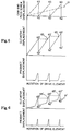
- Figure 5 is a graphical representation of the operation of a dispenser having both pressure relief and discrete dosing characteristics;
- Figure 6 is a graphical representation of the operation of a dispenser having exaggerated discrete dosing characteristics; and
- Figure 7 is a graphical representation of the operation of a dispenser having pressure relief characteristics but not discrete dosing characteristics.
- The swivel-up dispensing package, illustrated in Figure 1, utilizes a rotatable hand wheel 33' located at the base of the container body 21''. At the top of the body 21'' is applicating surface 22'' with one or more orifices 23''. The applicating surface 22'' may be a separate element and retained in position, as shown, by a snap bead or other means known to one skilled in the art. The interior wall of the body 21'' forms the product chamber, which holds the cream product, obviating the need for a separate cavity within the body 21''.
- Disposed within the body 21'' is axially movable elevator 27'' congruent to the inside of the body 21''. Rigidly and nonrotatably associated with the bottom of the elevator 27'' is internally threaded nut 32''. The nut 32'' should have an axial length approximately equal to the internal diameter of the nut 32'' to help provide stability to the elevator 27'' during its travel.
- The base of the body 21'' is arcuate, having a recess which is convex towards the applicating surface 22''. The base recess is disposed above the hand wheel 33' and has a centrally located axially tapered
hole 50 therein. The lowest elevation ofhole 50 is at the base recess. Thehole 50 is centered between a plurality ofcantilevered fingers 51, typically four. Eachfinger 51 has one end affixed to the container body 21'' base and extends upwardly towards the applicating surface 22'' and radially inwardly towards the central axis, terminating in a free end. The free ends of thefingers 51 are disposed at an elevation above the base and define the circumference of the top ofhole 50, which circumference is smaller than that ofhole 50 at the elevation of the base. The free ends offingers 51 also define the highest axial position ofhole 50. Eachfinger 51 is separated from theadjacent fingers 51 by slots, allowing eachfinger 51 to deflect independently of theother fingers 51. -
Fingers 51 having fixed ends disposed about the circumference ofbase hole 50 and which form an angle of about 70° relative to the horizontal are suitable. It will be apparent to one skilled in the art that thefingers 51 could also be cantilevered from other positions on the base or from the inside wall of the container body 21'', so long as thefingers 51 do not interfere with the movement of elevator 27''. It will be further apparent that thefingers 51 could be oriented at other angles, including parallel to the horizontal. - Disposed on the free end of each
finger 51, is a plurality of cams 34''. The cams 34'' may be shaped like saw tooth ratchet teeth, as shown, may be V-shaped, or any other profile judged to be advantageous by the user may be employed. For the embodiment shown herein, cams 34'' having a forward face 37'' ramped from about 20° to about 50°, preferably about 40° relative to the horizontal and an abrupt secondary face 38'' having an axial dimension ranging from 0.25 mm to 1.40 mm (0.010 to 0.055 inches), preferably from 0.51 mm to 0.89 mm, are generally suitable. The free end offinger 51 will accommodate five to seven cams 34'' thereon. If desired, a space or land (not shown) may be interposed between adjacent cams 34'' to provide for a desired number of cams 34'' on afinger 51 at a specified diameter and having a specified forward face 37'' ramp angle. - A polypropylene body 21'' having an integral base with a
hole 50 of approximately 17.0 mm (.657 inches) diameter and fourfingers 51 extending approximately 7.8 mm (.310 inches) in the axial direction, with free ends disposed on a diameter of approximately 11.9 mm (.470 inches), a circumferential dimension, or width, of approximately 6.4 mm (0.250 inches) and a radial dimension of not less than 1.9 mm (0.075 inches) has been found to work well. It is important that the radial dimension be large enough to provide sufficient contact area on the cam face to prevent excessive contact stress levels from occurring. - Referring to Figure 2, an axially rotatable hand wheel 33' is disposed beneath the arcuate base of the body 21'' in the recess of the base. The hand wheel 33' should have a exterior profile generally conforming to the recess of the base and extending outwardly from the sides of the
body 21˝ so that thehand wheel 33′ may be easily grasped by the user. - Nonrotatably associated with the
hand wheel 33′, preferably integral, iscoaxial feed screw 31˝. Disposed about the periphery of thefeed screw 31˝ is a plurality of ratchet teeth, orfollowers 35˝, adapted to coact with thecams 34˝ disposed on the free ends of thefingers 51 and preferably equal in number to thenumber cams 34˝ on thefingers 51. However, as shown, a minimum of about fourteeth 35˝ are necessary to provide stability for the mechanism and prevent erratic movement of theelevator 27˝. The ratchet teeth, orfollowers 35˝, of thefeed screw 31˝ may depend from acircumferential collar 52, as shown, or otherwise protrude laterally from the circumference of thefeed screw 31˝. - Either the
cams 34˝ orfollowers 35˝ should not be equally spaced about the central axis, such that any point in time, not all of thefollowers 35˝ are in an azmuthal position corresponding to the slots between thefingers 51. This can be accomplished by having each of the fourfingers 51 subtend an arc not equal to 90°. The slots are no wider than three-fourths of atooth 37˝, to provide stability to thefollowers 35˝. Preferentially, at least fourfollowers 35˝, spaced approximately 90° apart, are engaged with thecams 34˝ at all times. - The
hand wheel 33 and feedscrew 31˝ assembly has areturn spring 53 associated therewith. Thereturn spring 53 is preferentially incorporated into thehand wheel 33′, as shown, to prevent accidental dispensing of product should thehand wheel 33′ be bumped, as for example, during packing of the dispensing containers. One manner in which thereturn spring 53 can be incorporated into thehand wheel 33′ is to provide a plurality of spokes extending from the central portion of thehand wheel 33′ to the periphery of thehand wheel 33′ and radiating in a spiral pattern as shown. The spokes flex, allowing relative axial displacement betweenfeed screw 31˝ andhand wheel 33′. The spiral pattern of the spokes should be such that the spokes are tensioned as thehand wheel 33′ is rotated. Alternatively, it will be apparent to one skilled in the art, that thereturn spring 53 may be external thehand wheel 33′, such as a leaf spring (not shown) cantilevered from the interior of thecontainer body 21˝. - For the embodiment described herein, an
acetal hand wheel 33′ having a diameter at the lowermost portion of approximately 37.3 mm (1.47 inches) and a thickness of approximately 1.4 to 1.5 mm (.055 to .060 inches) is suitable. The plurality offollowers 35˝ may be disposed approximately 9.0 mm (.355 inches) above the top of thehand wheel 33′. Approximately 14.3 mm (.562 inches) above the top of thehand wheel 33′ is a suitable elevation for the axial position of thecollar 52. Acollar 52 having a diameter of about 7.5 mm (.297 inches) is sufficiently narrow to push through thehole 50 between the free ends of thefingers 51. The proximal end of thefeed screw 31˝ is preferentially disposed immediately above thecollar 52. Aspring 53 having a rate of approximately 3600 gm/cm (20 pounds per inch) is suitable. Such a spring rate can be approximated by a triskelion shapedspring 53 having spokes approximately 0.8 to 0.9 mm (.030 to .035 inches) in thickness, approximately 4.6 mm wide (.180 inches) and separated by slots approximately 1.0 mm (.040 inches) wide. - One suitable drive means has an
elevator 27˝ of approximately 11 square centimeters (1.7 square inches) and afeed screw 31˝ of approximately 5.6mm (.220 inches) diameter. Thefeed screw 31˝ is centered between approximately 28cams 34˝ on a diameter of about 13.8mm (.540 inches). Thecams 34˝ have aforward face 37˝ inclined at approximately 40° relative to the horizontal and an axial dimension of about 0.51mm (.020 inches). Afeed screw 31˝ which axially advances about 1.3mm (.05 inches) per rotation will dispense approximately .045 cubic centimeters of the cream product described above each time acam 34 is traced. If thefeed screw 31˝ is made to advance about 5.1mm (.20 inches) per rotation, approximately .18 cubic centimeters of the product is dispensed each time acam 34˝ is traced. - The package is assembled by inserting the elevator 27'' in the top of the product chamber and pushing the elevator 27'' downwardly until the nut 32'' protrudes through the
hole 50 in the base. The feed screw 31'' is then threadably engaged with the nut 32'', and the hand wheel 33', feed screw 31'' and elevator 27'' are pushed upwardly towards the top of the container body 21'', until thecollar 52 snaps into place above the plurality offingers 51. Thefingers 51 will spring outwardly until admitting thecollar 52, but will be compressed and engage thecollar 52 should one attempt to retract or pull the hand wheel 33' back out of the bottom of the dispensing package. The feedscrew 31'' is rotated via hand wheel 33', drawing the elevator 27'' assembly to its proximal, or lowermost, position. - In operation, as the user rotates the hand wheel 33', the followers 35'' ride up the ramped forward cam faces 37'', causing an axial displacement of the feed screw 31'' and hence elevator 27'' assembly, as shown in Figure 12. After reaching the crest 39'' of the cams 34'', the feed screw 31'' and elevator 27'' retract to the proximal position shown in Figure 4. As the feed screw 31'' is turned relative to the nut 32'' which is associated with the elevator 27'', a separate axial advance is caused thereby. The superposition of the displacements resulting from the interaction of the cams 34'' and followers 35'' and advance of the elevator 27'' due to relative rotation with the feedscrew, causes the elevator 27'' to advance enough to extrude product through the orifices 23'', then retract to relieve residual pressure on the product.
- As the user turns the hand wheel 33', it is restrained from axial movement by bearing against the base of the body 21''. However, as the feed screw 31'' rides up on the forward cam faces 37'' the spokes of
spring 53 are axially tensioned and provide the return force necessary to cause retraction of the feed screw 31'' and elevator 27'' assembly. After the feed screw 31'' assembly reaches the crest 39'' of the cam 34'' faces, the tension in the spokes of thereturn spring 53 retracts the feed screw 31'' and elevator 27'' assembly to the proximal position of Figure 4. - The dispenser of the invention described in Figures 1-4, are equipped to provide both discrete dosing and pressure relief of the cream product. Either characteristic can be amplified or reduced, as necessary to accommodate a specific combination of dispensing package and cream product. How these characteristics are related, and can be tuned, to provide the desired operation of the dispensing package, is best illustrated by referring to the graphical illustrations shown in Figures 5 through 7.
- For a product of a given yield pressure, the graphs illustrate that when less force is applied to expel the product through orifices 23'', less residual pressure will remain on the product. The amount of force applied to expel the product is related to the axial advance caused by rotation of the feedscrew and the cross-sectional area, and to a lesser extent distribution, of orifices 23''. As the yield pressure remaining within the product after dispensation increases, the amount of axial retraction caused by cams 34'' must be proportionally increased. This will prevent the product or its components from weeping onto the applicating surface 22''. Furthermore, the container body 21'' is not perfectly rigid and may be placed in tension by high residual yield pressures.
- The elevator displacement is graphically illustrated by Figure 5, which shows the relationships between elevator displacement and product dispensed on the vertical axis and hand wheel 33' rotation on the horizontal axis. A
line 61 drawn from the first origin represents the elevator 27'' displacement due to advance of the feed screw 31'' caused by rotation relative to nut 32'', without riding on the cams 34''. Lines 62-63-62 of the same graph represent the axial advance of elevator 27'' due to the follower 35'' tracing the profile of the saw tooth shaped cams 34''. - Since the displacement component of lines 62-63 is oriented in the same sense as the advance of the feed screw 31'' caused by rotation of the hand wheel 33' relative to nut 32'', the displacement will be constructively superimposed, causing the follower 35'' to undergo greater forward advance than if acted upon by either displacement alone. The displacements along lines 63-62 represents the retraction of the elevator 27'' and follower 35'', which is equal to and detracted from the forward axial displacement components, causing the follower 35'' to stop in an axial position governed by the advance of feed screw 31''.
- The two curves shown on the first horizontal axis of Figure 5, can be superimposed, as shown by the resultant curve on the second horizontal axis, to give the axial displacement of the elevator 27''. This superposition is shown by
points screw displacement line 61 is superimposed on the resultant cycle 62'-63'-62',line 61 will intersect at points 62'. - The retraction of the elevator 27'' occurs along the vertical line 63'-62' in Figure 5 after the product has been dispensed. When the elevator 27'' retracts, pressure on the product is relieved. This results in a deadband, shown as line segment 63'-65 in Figure 5. The deadband 63'-65 is the portion of the cycle in which no dispensing of product occurs during the initial phase of forwards axial movement. As shown on the third horizontal axis of Figure 5, product is not dispensed until the elevator 27'' is
near point 65, the furthest axial position attained during the preceding cycle. - This phenomenon allows one skilled in the art to enhance the discrete incremental dosing of a dispensing package which accomplishes pressure relief. By having the deadband 63'-65 control a large percentage of the dispensing cycle and dispensation occur during only a small part of the cycle, as shown by the third axis of Figure 5, the user is discouraged from trying to extrude a partial dose by rotating the hand wheel 33' to an intermediate position between the cams 34''. The amount of deadband 63'-65 in the cycle can be increased by reducing the lead angle of the feed screw 31''.
- By reducing the height of the secondary cam faces 38'' to a point below which the amount of retraction does not relieve enough residual pressure to prevent weeping of the cream product onto the applicating surface, the pressure relief characteristic of the dispensing package can be reduced. However, if the lead angle of the feed screw 31'' is adjusted, as described above, to provide a small advance of the elevator 27'', relative to the advance due to the cams 34'', the dosing feature described above is maintained.
- This dosing effect is characterized by dispensing product only during a short part of each cycle. Typically, when approximately one quarter or less of the rotation between "clicks" dispenses product, and the remaining rotation advances the elevator 27'' a distance which is insufficient to dispense product, the dosing effect defined by this invention is maintained. Dispensing, at a non-uniform rate, which gives discrete dosing can be maintained with a deadband 63'-65 of less than one-half the dispensing cycle, but a deadband of three-fourths cycle or greater is preferred.
- This dosing effect can be amplified, as graphically illustrated in Figure 6, by adding spaces or lands between the cams 34'' which cause the follower 35'' to dwell in the axial direction. There is negligible, if any, product dispensed in the large part of the cycle 62''-65' that is characterized only by the advance of the feed screw 31'' and by riding up the cam to the maximum forward displacement of the previous cycle. As shown on the second horizontal axis of Figure 6, the dispensation of the product will be effectively limited to that portion of the cycle 65'-63'', which includes both the axial advance of the cam 34'' and feed screw 31'' beyond the furthest axial position of the previous cycle.
- In a contrary fashion, the invention can be adapted to a dispensing package which emphasizes pressure relief but not the dosing effect. If the lead angle of the feed screw 31'' is increased, and the height of cams 34'' retracts the elevator 27'' a distance which is sufficient to relieve the residual pressure to a degree which prevents weeping onto surface 22'', as graphically illustrated by the increased slope of line 61'' of Figure 7, the invention increases the pressure relief without increasing the dosing effect. The height of the cams 34'' will provide enough pressure relief to prevent weeping and the increased lead angle of the thread of the feed screw 31'', will cause an exaggerated part of the cycle 65''-63''' to dispense product, as shown on the second horizontal axis of Figure 7. Thus, by selectively incorporating the proper cam height, feed screw lead angle, interior chamber cross section and properties of the cream product, the dispenser can be designed to amplify either the dosing characteristic, pressure relief characteristic, or both.
- It will be apparent to one skilled in the art that a variety of alternative drive means are known to advance a feed screw. For example, the proximal end of feed screw 31'' could be fitted with gear teeth. These gear teeth could then be engaged with the teeth of a mating gear which extends outside of the container body to be rotated by the user and in turn drive the feed screw 31''. Such a device is closely related to the embodiment as described above, differing only in that the rotatable hand wheel 33' is a gear which drives feed screw 31''.
- A variety of related drive means are known to advance the elevator 27'' of the swivel-up dispensing package described above. These rely on relative motion between a feed screw 31'' and a nut 32'' in the package. Either can be rotated to provide the movement of the elevator 27'' depending on the arrangement. A family of mechanisms could be constructed having a non-rotating nut 32'' and rotating feed screw 31''. For example, the nut 32'' can be attached to the elevator 27'' and an axially affixed feed screw 31'' rotated, or the nut 32'' could be mounted in fixed relationship with the package body 21'' and a feed screw 31'', rotatably affixed to the elevator 27'', turned to effect dispensing. Alternatively, a family of other mechanisms can be constructed having a rotating nut 32'' and a non-rotating feed screw 31''. So long as this relative rotation between the nut 32'' and feed screw 31'' is maintained, either family of mechanisms would be a feasible drive means for the dispensing package.
- There is also a variety of closely related and feasible alternative embodiments for the cam 34'' and follower 35'' system. The embodiment illustrated by the figures show a plurality of stationary cams 34'' and followers 35'' which are associated with the elevator 27'' through a rotating hand wheel 33'. The illustrated followers 35'' are specifically adapted to the saw tooth shaped profile of cams 34''. Obviously, a generic follower having one or more axial tines, equally suited to tracing a variety of cam 34'' profiles could be utilized. The designer may additionally wish to interchange the positions of the cam 34'' and follower 35'', such that the follower 35'' is stationary, and the cam 34'' is associated with the rotating component and elevator. This is easily accomplished since the elevator 27'' and follower 35'' can be associated with and driven either by riding on the axial motion of a follower 35'' or a cam 34''. Many other changes can be made without departure from the spirit and scope of the present invention.
Claims (10)
- A dispensing package for cream products, said dispensing package comprising:(a) a container body (21'') having an interior chamber of generally uniform cross section to contain said product and a lengthwise-extending central axis, said container body (21'') further comprising a base at the bottom of said container body (21'') and having a hole (50) therein;(b) an elevator (27'') having a cross section congruent to and mounted for axial movement within said chamber; and(c) a feed screw (31'') and a nut (32'') coaxial of said central axis and threadably engaged, one of said feed screw (31'') and said nut (32'') being non-rotatable and associated with said elevator (27''), the other being rotatable;
characterized in that said dispensing package additionally comprises:(d) a plurality of cantilevered fingers (51) affixed to one of said base and said container body (21'') and radially extending towards said central axis, said fingers (51) terminating in a free end having a plurality of one of cams (34'') and followers (35'') thereon; a plurality of one of cams (34'') and followers (35'') which are complementary to the one of cams (34'') and followers (35'') on said fingers (51) being associated with the one of said feed screw (31'') and said nut (32'') which is rotatable; and(e) an axially rotatable hand wheel (33') disposed below said base and non-rotatably affixed to the said one of said feed screw (31'') and said nut (32'') which is rotatable, said feed screw (31'') extending through said hole (50) in said base, whereby rotation of said feed screw (31'') or said nut (32'') advances said elevator (27'') while axially reciprocating said elevator (27'') one cycle for each predetermined increment of forward axial movement. - A dispensing package according to claim 1 characterized in that one of said cam (34'') and said follower (35'') is axially rotatable, the other of said cam (34'') and said follower (35'') is non-rotatable, said cam (34'') and follower (35'') being biased towards one another and adapted to provide axial reciprocating movement to the elevator (27''), reflecting successive rises and falls when one is rotated with respect to the other.
- A dispensing package according to claim 1 or 2 characterized in that the means to cause axial reciprocation results in a uniform retraction of the elevator (27'') for each predetermined increment of forward axial movement.
- A dispensing package according to any one of the preceding claims characterized in that the advance of the elevator (27'') is caused by the relative rotation between a nut (32'') and feed screw (31'') and is superimposed with axial reciprocation caused by a cam (34'') and follower (35'').
- A dispensing package according to claim 1 characterized in that the plurality of cams (34'') have a generally saw tooth shaped profile or a generally V-shaped profile and the plurality of followers (35'') have a generally saw tooth shaped profile or a generally V-shaped profile and is adapted to engage with said cams (34'').
- A dispensing package according to claim 5 characterized in that said cams (34'') have an axial dimension ranging from 0.25mm to 1.40mm and preferably ranging from 0.51mm to 0.89mm.
- A dispensing package according to claim 1 characterized by further comprising a circumferential collar (52) affixed to said feed screw (31'') and adapted to prevent said feed screw (31'') from being retracted through said hole (50) in said base.
- A dispensing package according to claim 1 characterized in that said plurality of fingers (51) is four.
- A dispensing package according to claim 8 characterized by one of said cams (34'') and followers (35'') are not equally spaced about said axis.
- A dispensing package according to claim 1 or 2 characterized in that said cam (34'') and said follower (35'') are biased towards one another by a spring (40) integral with said handwheel (33').
Applications Claiming Priority (2)
| Application Number | Priority Date | Filing Date | Title |
|---|---|---|---|
| US10884087A | 1987-10-15 | 1987-10-15 | |
| US108840 | 1987-10-15 |
Publications (3)
| Publication Number | Publication Date |
|---|---|
| EP0312165A2 EP0312165A2 (en) | 1989-04-19 |
| EP0312165A3 EP0312165A3 (en) | 1991-02-06 |
| EP0312165B1 true EP0312165B1 (en) | 1994-05-18 |
Family
ID=22324356
Family Applications (1)
| Application Number | Title | Priority Date | Filing Date |
|---|---|---|---|
| EP88202250A Expired - Lifetime EP0312165B1 (en) | 1987-10-15 | 1988-10-07 | Swivel-up type dispensing package |
Country Status (6)
| Country | Link |
|---|---|
| EP (1) | EP0312165B1 (en) |
| AT (1) | ATE105680T1 (en) |
| AU (1) | AU623350B2 (en) |
| BR (1) | BR8805360A (en) |
| DE (1) | DE3889613T2 (en) |
| ES (1) | ES2052689T3 (en) |
Families Citing this family (25)
| Publication number | Priority date | Publication date | Assignee | Title |
|---|---|---|---|---|
| US5007755A (en) * | 1989-10-05 | 1991-04-16 | The Gillette Company | Cosmetic product |
| FR2664509B1 (en) * | 1990-07-10 | 1994-04-15 | Lvmh Recherche | APPLICATOR DEVICE FOR MORE OR LESS VISCOUS LIQUID PRODUCTS. |
| US5547302A (en) * | 1994-07-29 | 1996-08-20 | The Procter & Gamble Company | Twist-up product dispenser having conformable apertured applicator surface |
| GB9521992D0 (en) * | 1995-10-27 | 1996-01-03 | Unilever Plc | Dispensing package |
| US5833382A (en) * | 1996-08-19 | 1998-11-10 | Helene Curtis, Inc. | Push-up dispenser suitable for dilatant materials |
| DE19921662B4 (en) * | 1999-04-23 | 2004-08-12 | Henkel Kgaa | Cream and deodorant dispenser |
| ATE258021T1 (en) | 1999-04-23 | 2004-02-15 | Henkel Kgaa | CREAM AND DEOPER DISPENSER |
| US6450716B1 (en) | 2001-08-13 | 2002-09-17 | The Plastek Group | Round rotary dispenser with pressure relief |
| US6398439B1 (en) | 2001-08-13 | 2002-06-04 | The Plastek Group | Oval rotary dispenser with pressure relief |
| US7874756B2 (en) | 2006-06-07 | 2011-01-25 | Beiersdorf Ag | Kit for the application of a fluid preparation |
| JP4932536B2 (en) * | 2007-02-28 | 2012-05-16 | 株式会社吉野工業所 | Fixed delivery container |
| EP2141091B1 (en) * | 2007-05-01 | 2016-03-23 | Japan Tobacco Inc. | Package of rod-shaped smoking article and its blank |
| DE102007022255B4 (en) | 2007-05-09 | 2009-07-09 | Beiersdorf Ag | Release plate for optically attractive antiperspirant formulations |
| ES2618314T3 (en) | 2008-10-27 | 2017-06-21 | Unilever N.V. | Antiperspirant compositions |
| EP2181692B1 (en) | 2008-10-27 | 2016-09-28 | Unilever PLC | Antiperspirant compositions |
| EP2221039B1 (en) | 2009-02-18 | 2017-11-22 | Unilever Plc, A Company Registered In England And Wales under company no. 41424 of Unilever House | Antiperspirant compositions |
| GB0910657D0 (en) | 2009-06-22 | 2009-08-05 | Unilever Plc | Antiperspirant compositions |
| US10427859B2 (en) | 2014-10-24 | 2019-10-01 | Conopco, Inc. | Dispenser for a cream, gel or soft solid composition |
| AU2015335173A1 (en) | 2014-10-24 | 2017-04-13 | Unilever Plc | Method of controlling perspiration |
| US10315832B2 (en) | 2016-09-23 | 2019-06-11 | The Procter & Gamble Company | Consumer product package |
| US10625927B2 (en) | 2016-09-23 | 2020-04-21 | The Procter & Gamble Company | Consumer product package |
| USD890434S1 (en) | 2016-11-10 | 2020-07-14 | Steven Tyler BROWN | Hand-held fluid-substance applicator |
| ES3020707T3 (en) * | 2017-01-04 | 2025-05-23 | Reflex Medical Corp | Metered dose topical applicator |
| USD848611S1 (en) | 2018-01-24 | 2019-05-14 | Reflex Medical Corp. | Metered dose topical applicator |
| CN120713340A (en) | 2024-03-29 | 2025-09-30 | 洽兴包装工业(中国)有限公司 | Paste container |
Family Cites Families (4)
| Publication number | Priority date | Publication date | Assignee | Title |
|---|---|---|---|---|
| US3756730A (en) * | 1971-12-08 | 1973-09-04 | Spatz Corp | Fluent material dispenser having ooze prevention means |
| US4356938A (en) * | 1980-10-10 | 1982-11-02 | Kayser Steven J | Caulking gun with pressure release mechanism |
| US4461407A (en) * | 1981-04-10 | 1984-07-24 | Danny Finnegan | Automatic pressure release mechanism for caulk gun |
| GB8319991D0 (en) * | 1983-07-25 | 1983-08-24 | Unit Moulders Ltd | Dispenser for semifluid substances |
-
1988
- 1988-10-07 AT AT88202250T patent/ATE105680T1/en active
- 1988-10-07 EP EP88202250A patent/EP0312165B1/en not_active Expired - Lifetime
- 1988-10-07 DE DE3889613T patent/DE3889613T2/en not_active Expired - Lifetime
- 1988-10-07 ES ES88202250T patent/ES2052689T3/en not_active Expired - Lifetime
- 1988-10-17 AU AU23922/88A patent/AU623350B2/en not_active Ceased
- 1988-10-17 BR BR8805360A patent/BR8805360A/en not_active IP Right Cessation
Also Published As
| Publication number | Publication date |
|---|---|
| EP0312165A2 (en) | 1989-04-19 |
| ATE105680T1 (en) | 1994-06-15 |
| DE3889613T2 (en) | 1995-01-12 |
| EP0312165A3 (en) | 1991-02-06 |
| AU623350B2 (en) | 1992-05-14 |
| ES2052689T3 (en) | 1994-07-16 |
| AU2392288A (en) | 1989-04-20 |
| DE3889613D1 (en) | 1994-06-23 |
| BR8805360A (en) | 1989-06-13 |
Similar Documents
| Publication | Publication Date | Title |
|---|---|---|
| CA1316881C (en) | Swivel-up type dispensing package | |
| AU623350B2 (en) | Swivel-up type dispensing package | |
| US4865231A (en) | Button type dispensing package | |
| DE69704965T2 (en) | Dosage dispenser | |
| US3756730A (en) | Fluent material dispenser having ooze prevention means | |
| DE69518482T2 (en) | Dispensers for cosmetics | |
| EP0858271B1 (en) | Dispensing package | |
| EP1065477B1 (en) | Liquid dose dispenser with device for counting a large number of dispensed doses | |
| DE68910370T2 (en) | Loadable dispenser with a sliding piston. | |
| CA2160745A1 (en) | Cream deodorant dispenser | |
| US5961007A (en) | Dispensing package | |
| US7306116B2 (en) | Dosing device | |
| US6210061B1 (en) | Dispensing apparatus | |
| DE4015549A1 (en) | MEASURING DONORS TO DISPENSING PASTOESER | |
| CA3017859C (en) | Propel/repel dispenser | |
| DE2528191B2 (en) | Dispenser for the individual dispensing of pre-dosed particles of a uniform shape and size | |
| US4826044A (en) | Dispenser for viscous fluids | |
| EP3982787B1 (en) | Device for dispensing a compound | |
| AU2021222227B2 (en) | A substance dispenser and a method of providing a substance dispenser | |
| WO1995004486A1 (en) | Dispenser for preferably solid compounds | |
| DE19828240A1 (en) | Twist-and-push stick with container and rotary drive mechanism | |
| DE3940967C1 (en) | Cosmetics applicator - has rotary housing with rear-threaded piston screwing into fixed thread way, and driving boss and flexible pawl arm | |
| DE2941416A1 (en) | Dispenser for pastes and viscous liquids - having piston on screw actuated by pusher with ratchet on top to deliver fixed amount of paste | |
| HUP0400099A2 (en) | Dispensing device for dosing cream-shaped or spreadable mass | |
| WO1998011000A1 (en) | Dispensing and dosing device |
Legal Events
| Date | Code | Title | Description |
|---|---|---|---|
| PUAI | Public reference made under article 153(3) epc to a published international application that has entered the european phase |
Free format text: ORIGINAL CODE: 0009012 |
|
| AK | Designated contracting states |
Kind code of ref document: A2 Designated state(s): AT BE CH DE ES FR GB GR IT LI LU NL SE |
|
| PUAL | Search report despatched |
Free format text: ORIGINAL CODE: 0009013 |
|
| AK | Designated contracting states |
Kind code of ref document: A3 Designated state(s): AT BE CH DE ES FR GB GR IT LI LU NL SE |
|
| 17P | Request for examination filed |
Effective date: 19910725 |
|
| 17Q | First examination report despatched |
Effective date: 19920218 |
|
| GRAA | (expected) grant |
Free format text: ORIGINAL CODE: 0009210 |
|
| AK | Designated contracting states |
Kind code of ref document: B1 Designated state(s): AT BE CH DE ES FR GB GR IT LI LU NL SE |
|
| REF | Corresponds to: |
Ref document number: 105680 Country of ref document: AT Date of ref document: 19940615 Kind code of ref document: T |
|
| REF | Corresponds to: |
Ref document number: 3889613 Country of ref document: DE Date of ref document: 19940623 |
|
| ITF | It: translation for a ep patent filed | ||
| ET | Fr: translation filed | ||
| REG | Reference to a national code |
Ref country code: ES Ref legal event code: FG2A Ref document number: 2052689 Country of ref document: ES Kind code of ref document: T3 |
|
| REG | Reference to a national code |
Ref country code: GR Ref legal event code: FG4A Free format text: 3011854 |
|
| EAL | Se: european patent in force in sweden |
Ref document number: 88202250.2 |
|
| PLBE | No opposition filed within time limit |
Free format text: ORIGINAL CODE: 0009261 |
|
| STAA | Information on the status of an ep patent application or granted ep patent |
Free format text: STATUS: NO OPPOSITION FILED WITHIN TIME LIMIT |
|
| 26N | No opposition filed | ||
| PGFP | Annual fee paid to national office [announced via postgrant information from national office to epo] |
Ref country code: AT Payment date: 20000918 Year of fee payment: 13 |
|
| PGFP | Annual fee paid to national office [announced via postgrant information from national office to epo] |
Ref country code: NL Payment date: 20000929 Year of fee payment: 13 |
|
| PGFP | Annual fee paid to national office [announced via postgrant information from national office to epo] |
Ref country code: SE Payment date: 20001004 Year of fee payment: 13 |
|
| PGFP | Annual fee paid to national office [announced via postgrant information from national office to epo] |
Ref country code: BE Payment date: 20001120 Year of fee payment: 13 |
|
| PGFP | Annual fee paid to national office [announced via postgrant information from national office to epo] |
Ref country code: LU Payment date: 20001201 Year of fee payment: 13 |
|
| PGFP | Annual fee paid to national office [announced via postgrant information from national office to epo] |
Ref country code: CH Payment date: 20010103 Year of fee payment: 13 |
|
| PG25 | Lapsed in a contracting state [announced via postgrant information from national office to epo] |
Ref country code: AT Free format text: LAPSE BECAUSE OF NON-PAYMENT OF DUE FEES Effective date: 20011007 Ref country code: LU Free format text: LAPSE BECAUSE OF NON-PAYMENT OF DUE FEES Effective date: 20011007 |
|
| PG25 | Lapsed in a contracting state [announced via postgrant information from national office to epo] |
Ref country code: SE Free format text: LAPSE BECAUSE OF NON-PAYMENT OF DUE FEES Effective date: 20011008 |
|
| PG25 | Lapsed in a contracting state [announced via postgrant information from national office to epo] |
Ref country code: CH Free format text: LAPSE BECAUSE OF NON-PAYMENT OF DUE FEES Effective date: 20011031 Ref country code: BE Free format text: LAPSE BECAUSE OF NON-PAYMENT OF DUE FEES Effective date: 20011031 Ref country code: LI Free format text: LAPSE BECAUSE OF NON-PAYMENT OF DUE FEES Effective date: 20011031 |
|
| REG | Reference to a national code |
Ref country code: GB Ref legal event code: IF02 |
|
| BERE | Be: lapsed |
Owner name: THE PROCTER & GAMBLE CY Effective date: 20011031 |
|
| PG25 | Lapsed in a contracting state [announced via postgrant information from national office to epo] |
Ref country code: NL Free format text: LAPSE BECAUSE OF NON-PAYMENT OF DUE FEES Effective date: 20020501 |
|
| EUG | Se: european patent has lapsed |
Ref document number: 88202250.2 |
|
| REG | Reference to a national code |
Ref country code: CH Ref legal event code: PL |
|
| NLV4 | Nl: lapsed or anulled due to non-payment of the annual fee |
Effective date: 20020501 |
|
| PGFP | Annual fee paid to national office [announced via postgrant information from national office to epo] |
Ref country code: GB Payment date: 20070918 Year of fee payment: 20 |
|
| PGFP | Annual fee paid to national office [announced via postgrant information from national office to epo] |
Ref country code: ES Payment date: 20071019 Year of fee payment: 20 Ref country code: DE Payment date: 20071031 Year of fee payment: 20 |
|
| PGFP | Annual fee paid to national office [announced via postgrant information from national office to epo] |
Ref country code: IT Payment date: 20071012 Year of fee payment: 20 |
|
| PGFP | Annual fee paid to national office [announced via postgrant information from national office to epo] |
Ref country code: FR Payment date: 20071004 Year of fee payment: 20 |
|
| PGFP | Annual fee paid to national office [announced via postgrant information from national office to epo] |
Ref country code: GR Payment date: 20071025 Year of fee payment: 20 |
|
| REG | Reference to a national code |
Ref country code: GB Ref legal event code: PE20 Expiry date: 20081006 |
|
| REG | Reference to a national code |
Ref country code: ES Ref legal event code: FD2A Effective date: 20081008 |
|
| PG25 | Lapsed in a contracting state [announced via postgrant information from national office to epo] |
Ref country code: ES Free format text: LAPSE BECAUSE OF EXPIRATION OF PROTECTION Effective date: 20081008 |
|
| PG25 | Lapsed in a contracting state [announced via postgrant information from national office to epo] |
Ref country code: GB Free format text: LAPSE BECAUSE OF EXPIRATION OF PROTECTION Effective date: 20081006 |