EP0311578B1 - Method and arrangement for an apparatus for operating by means of compressed air - Google Patents
Method and arrangement for an apparatus for operating by means of compressed air Download PDFInfo
- Publication number
- EP0311578B1 EP0311578B1 EP88850261A EP88850261A EP0311578B1 EP 0311578 B1 EP0311578 B1 EP 0311578B1 EP 88850261 A EP88850261 A EP 88850261A EP 88850261 A EP88850261 A EP 88850261A EP 0311578 B1 EP0311578 B1 EP 0311578B1
- Authority
- EP
- European Patent Office
- Prior art keywords
- cylinder
- air
- chamber
- flange
- piston
- Prior art date
- Legal status (The legal status is an assumption and is not a legal conclusion. Google has not performed a legal analysis and makes no representation as to the accuracy of the status listed.)
- Expired - Lifetime
Links
- 238000000034 method Methods 0.000 title abstract 2
- 238000013016 damping Methods 0.000 claims abstract description 9
- 238000007789 sealing Methods 0.000 claims description 7
- 238000006073 displacement reaction Methods 0.000 description 7
- 125000006850 spacer group Chemical group 0.000 description 7
- 239000013536 elastomeric material Substances 0.000 description 3
- 210000002445 nipple Anatomy 0.000 description 3
- 230000000694 effects Effects 0.000 description 2
- 238000004519 manufacturing process Methods 0.000 description 2
- 230000001133 acceleration Effects 0.000 description 1
- 238000010276 construction Methods 0.000 description 1
- 230000001419 dependent effect Effects 0.000 description 1
- 239000000203 mixture Substances 0.000 description 1
- 230000000717 retained effect Effects 0.000 description 1
- 239000011359 shock absorbing material Substances 0.000 description 1
- 230000007704 transition Effects 0.000 description 1
Images



Classifications
-
- B—PERFORMING OPERATIONS; TRANSPORTING
- B25—HAND TOOLS; PORTABLE POWER-DRIVEN TOOLS; MANIPULATORS
- B25C—HAND-HELD NAILING OR STAPLING TOOLS; MANUALLY OPERATED PORTABLE STAPLING TOOLS
- B25C1/00—Hand-held nailing tools; Nail feeding devices
- B25C1/04—Hand-held nailing tools; Nail feeding devices operated by fluid pressure, e.g. by air pressure
- B25C1/044—Hand-held nailing tools; Nail feeding devices operated by fluid pressure, e.g. by air pressure with movable main cylinder
- B25C1/045—Hand-held nailing tools; Nail feeding devices operated by fluid pressure, e.g. by air pressure with movable main cylinder main valve and main cylinder
Definitions
- the present invention relates to an arrangement for an apparatus for operating by means of compressed air, comprising a piston which is displaceable in a displaceable cylinder open at both ends and is designed for expulsion of fixing elements fed forward below the piston.
- An apparatus for operating by means of compressed air and arranged for expulsion of fixing elements fed forward out from a magazine is previously known, in which apparatus there is arranged, in a cylinder housing, a movable cylinder in which there is arranged, in turn, a piston which is displaceable between two end positions.
- the apparatus comprises, for controlling the air flow for displacement of the cylinder and the piston, a number of valve bodies for delivery as well as evacuation of compressed air to the cylinder housing.
- Such an apparatus is known from, for example, US A 3 190 187.
- valves are a factor which increases the cost of manufacturing the said apparatus, since the valve houses require high precision in the manufacturing in order for the valve needles and other elements incorporated in the valve to operate satisfactorily.
- the valves are sensitive to dirt which can be sucked in with the inlet air and result in operating disturbances in the apparatus.
- a pneumatic fastener driving tool including a housing with a displaceable hollow cylinder having a piston displaceable therein.
- the cylinder In its initial condition, i.e. before commencement of a work cycle, the cylinder is maintained in a lower position by means of air pressure in a first chamber located at the upper end of the cylinder.
- pressure in the first chamber is reduced and the air pressure in a second chamber located towards the lower end of the cylinder relative to the first chamber is great enough to cause upward displacement of the cylinder, thereby allowing air in the second chamber to flow into the cylinder via openings in the cylinder wall in the vicinity of the second chamber.
- Fig. 1 shows a side view of the apparatus
- Fig. 2 shows a section along the line II-II in Fig. 5
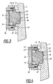
- Fig. 3 shows a partially broken section along the same section line as in Fig. 2, but with a cylinder and piston arranged on the apparatus in another working position than as shown in Fig. 2
- Fig. 4 shows a partially broken section along the same section line as in Fig. 2, but with the cylinder and piston in an upper end position
- Fig. 5 shows a section along the line V-V in Fig. 2.
- the apparatus comprises a handle part 1, a cylinder housing 2 arranged at one end of the handle part, and a cylinder head 3 arranged over the cylinder housing and a part of the handle part.
- a magazine 4 for fixing elements extends essentially parallel to the handle part 1 at a distance from the same and is connected to the handle part via a bar 5 and to the cylinder housing via a nozzle 6, which extends essentially transverse to the longitudinal direction of the magazine.
- a trigger 10 is arranged under the handle part 1 on the cylinder housing 2.
- an opener 11 designed for opening the magazine 4.
- the handle part comprises a slightly conical inlet channel 12 and a slightly conical outlet channel 13, which channels have their greatest diameter at the transition from the channel to the sound damper 7 or nipple 8 of the respective channel.
- the inlet channel 12 tapers towards the cylinder housing 2 and curves off against the cylinder housing and runs parallel to the latter round the outlet channel 13 up to an upper chamber 14.
- the upper chamber is in connection via an opening in its wall with an annular cylinder head chamber 15 which extends round an upper damping element 16 arranged in the cylinder head 3, which element is hereinafter called upper damper 16 and will be described in detail hereinafter.
- the cylinder housing 2 comprises an essentially cylindrical inner space 39 which is essentially transverse to the longitudinal directions of the inlet and outlet channels 12, 13 respectively, and which inner space tapers towards its lower end section as shown in Fig. 2 and is, at the said end section, provided with a cylinder part 17 whose diameter is clearly less than the greatest inside diameter of the cylinder housing.
- a displaceable cylinder 18 Arranged in the inner space 39 of the cylinder housing is a displaceable cylinder 18 open at both ends, the length of which is less than the length of the inner space of the cylinder housing.
- An end section of the cylinder 18 is arranged in the cylinder part 17, the diameter 18 of the cylinder being slightly less than the diameter of the cylinder part, in which connection there is formed around the cylinder, between its outer circumferential surface and the inner circumferential surface of the cylinder part, a bearing and guide for the cylinder.
- two cylinder flanges 19, 20 extend around the outer circumferential surface of the cylinder, the outer diameter of the cylinder flanges being slightly less than the diameter of the inner space 39 of the cylinder housing.
- the cylinder flanges are provided with an annular groove in which is arranged a sealing element 21 which is preferably made of an elastomeric material and can be composed of an O-ring.
- a spacer ring 22 Arranged under the cylinder flange 20 round the cylinder with support against the inner circumferential surface of the cylinder housing is a spacer ring 22 having a groove turned towards the outer circumferential surface of the cylinder, in which groove is arranged a second sealing element, preferably in the form of an elastomeric material such as an O-ring.
- the said sealing element creates an airtight seal against the outer circumferential surface of the cylinder.
- the cylinder 18 is provided with a number of openings 23, hereinafter called return openings 23, arranged in the cylinder wall between the first cylinder flange 19 and the second cylinder flange 20.
- the cylinder moreover has at least one, preferably several other openings 24 which lead into an annular groove which runs round the outer circumferential surface of the cylinder, in which groove a cover element 25 is arranged and preferably endlessly and made of an elastomeric material and can be in the form of an elastomeric band arranged in the groove, in which connection the said openings 24 together with the covering element have the function of a nonreturn valve.
- a lower damper 26 Arranged in the cylinder part 17 is a lower damper 26 whose diameter is only slightly less than the inner diameter of the cylinder part, and which damper is provided with a centrally placed opening 27.
- the damper is preferably made of a shock-absorbing material such as polyurethanerythane(sic) rubber or a similar rubber mixture.
- a third opening 28 which forms a connection between the inner space of the cylinder and a return chamber 30 extending round the cylinder.
- a displaceable piston 31 of cylindrical cross section area is arranged in the cylinder, in which connection the diameter of the piston is slightly less than the inner diameter of the cylinder.
- the piston has an annular groove in which a seal is arranged and which forms an airtight or almost airtight seal against the inner circumferential surface of the cylinder 18.
- a driver element 32 Extending out from the piston, in the imagined direction of movement of the piston, is a driver element 32 preferably in the form of an elongate flat element whose cross section area is clearly smaller than the opening 27.
- the driver element 32 extends a distance into a channel which extends through the nozzle 6.
- valve opening 33 Arranged in the wall of the inlet channel 12 over the trigger 10 is a valve opening 33 which forms a connecting path for the air past a valve 34, preferably a needle valve into a second inlet channel 35 oblique relative to the longitudinal direction of the inlet channel, which second inlet channel 35 empties into an intermediate chamber 36 which in turn runs round the cylinder 18 between the upper end face of the spacer ring 22 and the lower face of the second cylinder flange 20 and whose capacity depends on the position of the cylinder in the space 39 of the cylinder housing.
- a valve 34 preferably a needle valve into a second inlet channel 35 oblique relative to the longitudinal direction of the inlet channel, which second inlet channel 35 empties into an intermediate chamber 36 which in turn runs round the cylinder 18 between the upper end face of the spacer ring 22 and the lower face of the second cylinder flange 20 and whose capacity depends on the position of the cylinder in the space 39 of the cylinder housing.
- the cylinder head 3 is arranged in a tight-fitting position over the cylinder 18 and the cylinder housing 2, and which cylinder head has, arranged on its inner side in a position directly above the upper open end of the cylinder 18, a recess 37 provided with an annular knob section 38 directed towards the open end of the cylinder.
- the upper damper 16 is arranged in the said recess with an attachment part.
- first flange 41 Extending round the cylindrical damper 16 over the annular end section of the recess is a first flange 41 which, with its tangential end face, forms together with the cylinder head 3 an inner wall of the cylinder head chamber 15, in which connection the diameter of the first flange 41 is greater than the inner diameter of the cylinder 18, but is less than the outer diameter of the cylinder and is adapted to bear against an annular end face 47 of the cylinder.
- a preferably cylindrical spacer element 42 Arranged under the first flange is a preferably cylindrical spacer element 42, whose diameter is clearly less than the diameter of the first flange, and which spacer element forms a connection element between the first flange 41 and a second cylindrical flange 43, whose diameter is greater than the diameter of the spacer element, but is less than the diameter of the first flange, in which connection the diameter of the second flange 43 coincides with or is slightly less than the inner diameter of the cylinder 18, so that an annular groove is formed between the first flange 41 and the second flange 43.
- a buffer part 44 Arranged under the second flange is a buffer part 44 whose diameter is clearly less than the inner diameter of the cylinder 18 and constitutes a damping and spacer element for the piston 31 in an upper position so that the piston, via a section of its upper thrust face, bears against the buffer part 44 at a distance from the second flange 43.
- the cylinder head bears with an annular projecting section in the inner space 39 of the cylinder housing 2, in which connection there is formed an upper annular chamber 45 between the said annular part and the upper damper 16, which chamber 45 in turn forms a flow channel 46 from the cylinder head chamber 15 past the upper damper into the cylinder 18, as emerges most clearly from Fig. 2.
- the present apparatus is connected, at the nipple 8, by means of a preferably flexible tubing to a compressed air network, in which connection air flows in, in the direction of the arrow 50, up into the upper chamber 14 and through the valve opening 33 past the valve 34, through the second inlet channel 35 up into the intermediate chamber 36, in which connection the cylinder 18 is retained in its upper position.
- a compressed air network in which connection air flows in, in the direction of the arrow 50, up into the upper chamber 14 and through the valve opening 33 past the valve 34, through the second inlet channel 35 up into the intermediate chamber 36, in which connection the cylinder 18 is retained in its upper position.
- an upper annular end section of the cylinder 18 bears and thus seals against the first flange 41, in which connection the second flange 43 forms a lip seal against the inner circumferential surface of the cylinder.
- the flow channel 46 from the cylinder head chamber 15 into the cylinder 18 is closed.
- valve 34 closes the valve opening 33 at the same time as a return opening is formed past the valve, in which connection the second inlet channel 35 and the intermediate chamber 36 are evacuated of air which can flow past the valve out at the trigger 10.
- connection the second inlet channel 35 and the intermediate chamber 36 are evacuated of air which can flow past the valve out at the trigger 10.
- connection the pressure acting to maintain the cylinder against the second cylinder flange 20 is reduced, in which connection the pressure against the upper annular end face 47 of the cylinder exceeds the pressure against the second cylinder flange 20, and the cylinder 18 is displaced towards its other end position in the inner space 39 of the cylinder housing, in which connection air is allowed to flow past the first flange 41 and the annular end face 47 of the cylinder in the annular groove between the first and second flange 41, 43 of the upper damper 16, as shown in Fig.
- the outer annular end face of the piston 31 comes to bear against the lower damper 26 in its second end position, as shown in Fig. 2.
- the air which is located under the piston in the cylinder and which is at atmospheric pressure, is squeezed out both through the third opening 28 into the return chamber 30 and out through the opening 27.
- an overpressure is maintained in the cylinder 18 by means of air which flows from the inlet channel 12 into the cylinder and which exerts a pressure on the upper thrust face of the piston.
- the driver element 32 is displaced through the opening 27 in the lower damper 26 through the channel in the nozzle 6 and hits with great force, and drives out from the nozzle, a fixing element fed from the magazine 4, such as a staple.
- valve opening 33 When the trigger is released, the valve opening 33 is uncovered and air is allowed to flow into the valve opening 33 past the valve 34, through the second inlet channel 35 up into the intermediate chamber 36, in which connection an overpressure is built up in the intermediate chamber, and which air pressure exerts a pressure on the second cylinder flange 20, which displaces the cylinder 18 upwards to bear with its annular end face 47 against the first flange 41 of the upper damper 16.
- the flow channel 46 is closed at the same time as the return openings come in front of the outlet channel 13, in which connection the pressure in the cylinder quickly falls. Since the outlet channel 13 is conical, with its greatest opening at the sound damper 7, the evacuation of the air in the direction of the arrow 51 is facilitated and accelerated.
- the nonreturn valve 24, 25 prevents the air from flowing back into the cylinder above the piston. In this way a pressure difference is created between the air in the return chamber 30 and the cylinder 18, in which connection air flows through the openings 28 and the air gap at the outer circumferential surface of the cylinder and the cylinder part 17, in which connection the pressure in the cylinder above the piston 31 is less than the pressure below the latter, in such a way that the air pressure below the piston, between the piston and the lower damper 26, displaces the piston in the cylinder 18 to bear against the buffer part 44 of the upper damper 16, in which connection, during the movement of the piston, the air compressed in the cylinder is continuously evacuated through the return openings 23 out into the outlet channel 13.
- the piston is maintained in its upper end position by the friction between the annular seals of the piston and the inner circumferential surface of the cylinder.
- a fixing element is fed from the magazine in a manner known per se out into the channel in the nozzle.
- the illustrated apparatus according to the invention is, as emerges from what has been stated above, extremely simple in its construction and design.
- the apparatus only comprises one valve, labour costs are reduced and operational reliability increased.
- the special design of the upper damper constitutes a delay in the displacement of the piston relative to the displacement of the cylinder,-in which connection an overpressure has time to build up and the opening to the outlet channel 13 has time to closed before the pressure is turned on the upper pressure surface of the piston. In this way the acceleration of the piston is increased without higher air pressure being required, and at the same time the weight of the piston can be reduced.
- the compressed air necessary for the displacement of the piston and cylinder can be prevented from being conveyed past the valve, and instead is allowed to act directly on the piston. It will emerge from the above that the present apparatus is extremely simple and inexpensive to produce and is easy to assemble.
Landscapes
- Physics & Mathematics (AREA)
- Fluid Mechanics (AREA)
- Engineering & Computer Science (AREA)
- Mechanical Engineering (AREA)
- Portable Nailing Machines And Staplers (AREA)
- Nozzles (AREA)
- Air Transport Of Granular Materials (AREA)
- Processing Of Terminals (AREA)
- Spinning Or Twisting Of Yarns (AREA)
- Hydraulic Clutches, Magnetic Clutches, Fluid Clutches, And Fluid Joints (AREA)
- Fluid-Damping Devices (AREA)
- Air-Flow Control Members (AREA)
- Fluid-Pressure Circuits (AREA)
- Actuator (AREA)
- Control Of Fluid Pressure (AREA)
Abstract
Description
- The present invention relates to an arrangement for an apparatus for operating by means of compressed air, comprising a piston which is displaceable in a displaceable cylinder open at both ends and is designed for expulsion of fixing elements fed forward below the piston.
- An apparatus for operating by means of compressed air and arranged for expulsion of fixing elements fed forward out from a magazine is previously known, in which apparatus there is arranged, in a cylinder housing, a movable cylinder in which there is arranged, in turn, a piston which is displaceable between two end positions. The apparatus comprises, for controlling the air flow for displacement of the cylinder and the piston, a number of valve bodies for delivery as well as evacuation of compressed air to the cylinder housing. Such an apparatus is known from, for example, US A 3 190 187.
- In this respect the valves are a factor which increases the cost of manufacturing the said apparatus, since the valve houses require high precision in the manufacturing in order for the valve needles and other elements incorporated in the valve to operate satisfactorily. In addition, the valves are sensitive to dirt which can be sucked in with the inlet air and result in operating disturbances in the apparatus.
- Another disadvantage with the previously known apparatuses is that the compressed air acted upon by means of the valve is not conveyed directly for affecting and displacing the piston arranged in the cylinder, but the compressed air is passed through the often relatively small flow areas of the valve, which in turn involves a slow cylinder-filling and thus a lower speed of the piston. In order to obtain a high speed in the piston, a high pressure for the air is required under these circumstances in order to accelerate the piston, which usually involves a recoil effect on the apparatus during the piston movement.
- From US A 4 030 655 there is known a pneumatic fastener driving tool including a housing with a displaceable hollow cylinder having a piston displaceable therein. In its initial condition, i.e. before commencement of a work cycle, the cylinder is maintained in a lower position by means of air pressure in a first chamber located at the upper end of the cylinder. When the work cycle is initiated, pressure in the first chamber is reduced and the air pressure in a second chamber located towards the lower end of the cylinder relative to the first chamber is great enough to cause upward displacement of the cylinder, thereby allowing air in the second chamber to flow into the cylinder via openings in the cylinder wall in the vicinity of the second chamber. This flow of air causes displacement of the piston within the cylinder to drive out a fixing element. Once the fixing element has been expelled, air pressure in a third, lower chamber effects the return of the cylinder and piston to the initial condition. Such an apparatus is, however, rather cumbersome.
- An apparatus for operating by means of compressed air is obtained by means of the invention as defined in claim 1, which eliminates the disadvantages of the previously known solutions.
- Preferred embodiments of the present invention are detailed in the dependent claims.
- The invention will be described in greater detail below on the basis of an exemplary embodiment with reference to the attached drawings in which Fig. 1 shows a side view of the apparatus, Fig. 2 shows a section along the line II-II in Fig. 5, Fig. 3 shows a partially broken section along the same section line as in Fig. 2, but with a cylinder and piston arranged on the apparatus in another working position than as shown in Fig. 2, Fig. 4 shows a partially broken section along the same section line as in Fig. 2, but with the cylinder and piston in an upper end position, and Fig. 5 shows a section along the line V-V in Fig. 2.
- The invention will be described below on the basis of an exemplary embodiment with a compressed air-driven stapler, but it can of course be applied to any compressed air-driven apparatus for expulsion of fixing elements. As shown in Fig. 1 the apparatus comprises a handle part 1, a
cylinder housing 2 arranged at one end of the handle part, and acylinder head 3 arranged over the cylinder housing and a part of the handle part. Amagazine 4 for fixing elements extends essentially parallel to the handle part 1 at a distance from the same and is connected to the handle part via abar 5 and to the cylinder housing via anozzle 6, which extends essentially transverse to the longitudinal direction of the magazine. Arranged at the rear end section of the handle part are a sound-absorbingelement 7, hereinafter referred to assound damper 7, for outlet air and anipple 8 for inlet air. Atrigger 10 is arranged under the handle part 1 on thecylinder housing 2. Arranged on thebar 5 is anopener 11 designed for opening themagazine 4. - As shown in Fig. 2 the handle part comprises a slightly
conical inlet channel 12 and a slightlyconical outlet channel 13, which channels have their greatest diameter at the transition from the channel to thesound damper 7 ornipple 8 of the respective channel. Theinlet channel 12 tapers towards thecylinder housing 2 and curves off against the cylinder housing and runs parallel to the latter round theoutlet channel 13 up to anupper chamber 14. The upper chamber is in connection via an opening in its wall with an annularcylinder head chamber 15 which extends round anupper damping element 16 arranged in thecylinder head 3, which element is hereinafter calledupper damper 16 and will be described in detail hereinafter. - The
cylinder housing 2 comprises an essentially cylindricalinner space 39 which is essentially transverse to the longitudinal directions of the inlet andoutlet channels cylinder part 17 whose diameter is clearly less than the greatest inside diameter of the cylinder housing. Arranged in theinner space 39 of the cylinder housing is adisplaceable cylinder 18 open at both ends, the length of which is less than the length of the inner space of the cylinder housing. An end section of thecylinder 18 is arranged in thecylinder part 17, thediameter 18 of the cylinder being slightly less than the diameter of the cylinder part, in which connection there is formed around the cylinder, between its outer circumferential surface and the inner circumferential surface of the cylinder part, a bearing and guide for the cylinder. At the opposite end section of the cylinder a distance from its open end, twocylinder flanges inner space 39 of the cylinder housing. The cylinder flanges are provided with an annular groove in which is arranged asealing element 21 which is preferably made of an elastomeric material and can be composed of an O-ring. Arranged under thecylinder flange 20 round the cylinder with support against the inner circumferential surface of the cylinder housing is aspacer ring 22 having a groove turned towards the outer circumferential surface of the cylinder, in which groove is arranged a second sealing element, preferably in the form of an elastomeric material such as an O-ring. The said sealing element creates an airtight seal against the outer circumferential surface of the cylinder. - The
cylinder 18 is provided with a number ofopenings 23, hereinafter calledreturn openings 23, arranged in the cylinder wall between thefirst cylinder flange 19 and thesecond cylinder flange 20. The cylinder moreover has at least one, preferably severalother openings 24 which lead into an annular groove which runs round the outer circumferential surface of the cylinder, in which groove acover element 25 is arranged and preferably endlessly and made of an elastomeric material and can be in the form of an elastomeric band arranged in the groove, in which connection the saidopenings 24 together with the covering element have the function of a nonreturn valve. - Arranged in the
cylinder part 17 is alower damper 26 whose diameter is only slightly less than the inner diameter of the cylinder part, and which damper is provided with a centrally placed opening 27. The damper is preferably made of a shock-absorbing material such as polyurethanerythane(sic) rubber or a similar rubber mixture. - Under the nonreturn valve in the cylinder wall there is arranged a third opening 28, or preferably several, which forms a connection between the inner space of the cylinder and a
return chamber 30 extending round the cylinder. Adisplaceable piston 31 of cylindrical cross section area is arranged in the cylinder, in which connection the diameter of the piston is slightly less than the inner diameter of the cylinder. The piston has an annular groove in which a seal is arranged and which forms an airtight or almost airtight seal against the inner circumferential surface of thecylinder 18. Extending out from the piston, in the imagined direction of movement of the piston, is adriver element 32 preferably in the form of an elongate flat element whose cross section area is clearly smaller than the opening 27. Thedriver element 32 extends a distance into a channel which extends through thenozzle 6. - Arranged in the wall of the
inlet channel 12 over thetrigger 10 is avalve opening 33 which forms a connecting path for the air past avalve 34, preferably a needle valve into asecond inlet channel 35 oblique relative to the longitudinal direction of the inlet channel, whichsecond inlet channel 35 empties into anintermediate chamber 36 which in turn runs round thecylinder 18 between the upper end face of thespacer ring 22 and the lower face of thesecond cylinder flange 20 and whose capacity depends on the position of the cylinder in thespace 39 of the cylinder housing. - As shown in Figs. 1 and 2 the
cylinder head 3 is arranged in a tight-fitting position over thecylinder 18 and thecylinder housing 2, and which cylinder head has, arranged on its inner side in a position directly above the upper open end of thecylinder 18, arecess 37 provided with anannular knob section 38 directed towards the open end of the cylinder. As shown in Figs. 3 and 4 theupper damper 16 is arranged in the said recess with an attachment part. Extending round thecylindrical damper 16 over the annular end section of the recess is afirst flange 41 which, with its tangential end face, forms together with thecylinder head 3 an inner wall of thecylinder head chamber 15, in which connection the diameter of thefirst flange 41 is greater than the inner diameter of thecylinder 18, but is less than the outer diameter of the cylinder and is adapted to bear against anannular end face 47 of the cylinder. Arranged under the first flange is a preferablycylindrical spacer element 42, whose diameter is clearly less than the diameter of the first flange, and which spacer element forms a connection element between thefirst flange 41 and a secondcylindrical flange 43, whose diameter is greater than the diameter of the spacer element, but is less than the diameter of the first flange, in which connection the diameter of thesecond flange 43 coincides with or is slightly less than the inner diameter of thecylinder 18, so that an annular groove is formed between thefirst flange 41 and thesecond flange 43. Arranged under the second flange is abuffer part 44 whose diameter is clearly less than the inner diameter of thecylinder 18 and constitutes a damping and spacer element for thepiston 31 in an upper position so that the piston, via a section of its upper thrust face, bears against thebuffer part 44 at a distance from thesecond flange 43. - The cylinder head bears with an annular projecting section in the
inner space 39 of thecylinder housing 2, in which connection there is formed an upperannular chamber 45 between the said annular part and theupper damper 16, whichchamber 45 in turn forms aflow channel 46 from thecylinder head chamber 15 past the upper damper into thecylinder 18, as emerges most clearly from Fig. 2. - The present apparatus is connected, at the
nipple 8, by means of a preferably flexible tubing to a compressed air network, in which connection air flows in, in the direction of thearrow 50, up into theupper chamber 14 and through the valve opening 33 past thevalve 34, through thesecond inlet channel 35 up into theintermediate chamber 36, in which connection thecylinder 18 is retained in its upper position. As shown in Fig. 4 an upper annular end section of thecylinder 18 bears and thus seals against thefirst flange 41, in which connection thesecond flange 43 forms a lip seal against the inner circumferential surface of the cylinder. In this connection theflow channel 46 from thecylinder head chamber 15 into thecylinder 18 is closed. - When the
trigger 10 is squeezed, thevalve 34 closes the valve opening 33 at the same time as a return opening is formed past the valve, in which connection thesecond inlet channel 35 and theintermediate chamber 36 are evacuated of air which can flow past the valve out at thetrigger 10. In this way the pressure acting to maintain the cylinder against thesecond cylinder flange 20 is reduced, in which connection the pressure against the upperannular end face 47 of the cylinder exceeds the pressure against thesecond cylinder flange 20, and thecylinder 18 is displaced towards its other end position in theinner space 39 of the cylinder housing, in which connection air is allowed to flow past thefirst flange 41 and theannular end face 47 of the cylinder in the annular groove between the first andsecond flange upper damper 16, as shown in Fig. 3. In this way an overpressure is built up in the annular groove formed in thespacer element 42, and the compressed air thus acts on the entireannular end face 47 of the cylinder, this resulting in an extremely quick displacement of thecylinder 18 towards thelower damper 26. When thecylinder 18 is displaced relative to theupper damper 16 and thesecond flange 43 ceases to bear against the inner circumferential surface of thecylinder 18, the air enclosed in the annular groove and thecylinder head chamber 15 flows out with great force in theflow channel 46 and hits the upper pressure surface of thepiston 31, in which connection the piston is displaced in the cylinder at great speed towards thelower damper 26. Immediately before theflange 43 ceases to bear against the inner circumferential surface of thecylinder 18, thecylinder flange 19 has passed theoutlet channel 13 and thus air is prevented from flowing directly out through theopenings 23 in the cylinder wall out into theoutlet channel 13. - The outer annular end face of the
piston 31 comes to bear against thelower damper 26 in its second end position, as shown in Fig. 2. During the downward movement of the piston the air, which is located under the piston in the cylinder and which is at atmospheric pressure, is squeezed out both through the third opening 28 into thereturn chamber 30 and out through the opening 27. When thepiston 31 is in its lower position, as shown in Fig. 2, and thetrigger 10 is held squeezed in, an overpressure is maintained in thecylinder 18 by means of air which flows from theinlet channel 12 into the cylinder and which exerts a pressure on the upper thrust face of the piston. In this way a pressure compensation of air is brought about between thecylinder 18 and thereturn chamber 30, in which connection air flows out through theopenings 24 and past the coveringelastomeric element 25 whose bearing pressure against the openings is no greater than required for the said pressure compensation to be easily effected. - During the downward movement of the piston, the
driver element 32 is displaced through the opening 27 in thelower damper 26 through the channel in thenozzle 6 and hits with great force, and drives out from the nozzle, a fixing element fed from themagazine 4, such as a staple. - When the trigger is released, the
valve opening 33 is uncovered and air is allowed to flow into the valve opening 33 past thevalve 34, through thesecond inlet channel 35 up into theintermediate chamber 36, in which connection an overpressure is built up in the intermediate chamber, and which air pressure exerts a pressure on thesecond cylinder flange 20, which displaces thecylinder 18 upwards to bear with itsannular end face 47 against thefirst flange 41 of theupper damper 16. In this way theflow channel 46 is closed at the same time as the return openings come in front of theoutlet channel 13, in which connection the pressure in the cylinder quickly falls. Since theoutlet channel 13 is conical, with its greatest opening at thesound damper 7, the evacuation of the air in the direction of thearrow 51 is facilitated and accelerated. Thenonreturn valve return chamber 30 and thecylinder 18, in which connection air flows through theopenings 28 and the air gap at the outer circumferential surface of the cylinder and thecylinder part 17, in which connection the pressure in the cylinder above thepiston 31 is less than the pressure below the latter, in such a way that the air pressure below the piston, between the piston and thelower damper 26, displaces the piston in thecylinder 18 to bear against thebuffer part 44 of theupper damper 16, in which connection, during the movement of the piston, the air compressed in the cylinder is continuously evacuated through thereturn openings 23 out into theoutlet channel 13. The piston is maintained in its upper end position by the friction between the annular seals of the piston and the inner circumferential surface of the cylinder. During the return movement of the piston to its first upper end position, a fixing element is fed from the magazine in a manner known per se out into the channel in the nozzle. - The illustrated apparatus according to the invention is, as emerges from what has been stated above, extremely simple in its construction and design. By virtue of the fact that the apparatus only comprises one valve, labour costs are reduced and operational reliability increased. In addition, the special design of the upper damper constitutes a delay in the displacement of the piston relative to the displacement of the cylinder,-in which connection an overpressure has time to build up and the opening to the
outlet channel 13 has time to closed before the pressure is turned on the upper pressure surface of the piston. In this way the acceleration of the piston is increased without higher air pressure being required, and at the same time the weight of the piston can be reduced. By means of the present invention, the compressed air necessary for the displacement of the piston and cylinder can be prevented from being conveyed past the valve, and instead is allowed to act directly on the piston. It will emerge from the above that the present apparatus is extremely simple and inexpensive to produce and is easy to assemble. - The invention is not limited to the exemplary embodiment mentioned above and shown in the drawings, but can be varied within the scope of the following patent claims.
Claims (7)
- An apparatus for operating by means of compressed air comprising: a housing (2), a displaceable hollow cylinder (18) with opposite first and second ends in said housing (2), a piston (31) displaceable in said cylinder (18), means for displacing said cylinder (18) and said piston (31) by the action of air betwen an upper and a lower end position, damping elements (16, 26) for said cylinder (18) and piston (31) located at said upper and lower end positions, an inlet channel (12) and an outlet channel (13) with a valve (33, 34) for controlling air flow therebetween, a first air chamber (14) at the first end of said housing (2) in communication with said air inlet (12), a second air chamber (36) in said housing (2) located towards its second end relative to the first air chamber (14), said second air chamber (36) being connected with said air inlet (12) downstream of said valve (33, 34), a first sealing element (41) which is positioned to bear against a section of an annular end face (47) at one end of said cylinder (18) when said cylinder is in its upper end position to prevent admittance of air into said cylinder (18) past said annular end face (47), a lower air chamber (30) in said housing (2) towards its second end, which lower chamber is in connection with the inside of said cylinder (18) by means of at least one opening (28) in a wall of said cylinder, there being at least one other opening (23) in said cylinder wall which is in connection with said outlet channel (13) depending on the position of said cylinder (18), whereby said valve (33, 34) is operable for controlling the pressure in said first and second air chambers (14, 36 resp.) to set said cylinder (18) in motion, and means being provided to set said piston (31) in motion after said cylinder (18) has been moved.
- An apparatus according to claim 1, characterized by a second sealing element (43) which is located at a distance from said first sealing element (41) and which is positioned to bear against an inner circumferential surface of said cylinder (18) when said cylinder is in said upper end position.
- An apparatus according to claim 2, characterized in that the damping element (16) at said upper end position comprises said first and second sealing elements (41, 43 resp.) and comprises respectively a first flange (41) having a diameter which exceeds the inner diameter of said cylinder (18) and a second flange (43) having a diameter which is slightly less than the inner diameter of said cylinder (18), said cylinder in its first end position bearing with its annular end face (47) against a surface of said first flange (41), and said second flange (43) bearing with one surface against said inner circumferential surface of said cylinder (18).
- An apparatus according to claim 2 or 3, characterized in that said second air chamber (36) is delimited by the outer circumferential surface of said cylinder (18) and the inner circumferential surface of said housing (2) and is in connection with said air inlet channel (12) via the inside of said cylinder (18) when the position of said cylinder is such that said inside of said cylinder is in communication with said first air chamber (14), said first air chamber (14) being continuously supplied with air from said air inlet channel (12) in use of the apparatus.
- An apparatus according to claim 3 or 4, characterized in that a channel (35) leads to said second chamber (36) and when air pressure in said second chamber (36) is sufficiently reduced relative to that in said first upper chamber (14) by evacuation of air through said channel (35), the air pressure in said first chamber (14) exerts a force against said annular end face (47) of said cylinder (18), which end face (47) projects radially beyond said first flange (41), and said cylinder (18) is moved away from its first end position towards its second end position to open a passage (46) for air flow between said first flange (41) and said annular end face (47) of said cylinder (18) to an annular air channel (42) formed by a groove between said first flange (41) and said second flange (43), further movement of said cylinder (18) beyond said second flange (43) also opening the inside of said cylinder (18) to air flow from said first chamber (14).
- An apparatus according to any of claims 3 to 5, characterized in that said piston (31) bears against said damping element (16) at said upper end position at a distance from said second flange (43).
- An apparatus according to any of the preceding claims, characterized in that said damping element (16) at said upper end position is substantially cylindrical and is located in an end section of said housing (2), a section of said upper damping element (16) projecting into said cylinder (18) to a varying degree depending on the position of said cylinder.
Priority Applications (1)
| Application Number | Priority Date | Filing Date | Title |
|---|---|---|---|
| AT88850261T ATE99211T1 (en) | 1987-08-13 | 1988-08-03 | PNEUMATIC OPERATED DEVICE AND METHOD OF USE. |
Applications Claiming Priority (2)
| Application Number | Priority Date | Filing Date | Title |
|---|---|---|---|
| SE8703146A SE462470B (en) | 1987-08-13 | 1987-08-13 | DEVICE FOR APPLIANCE FOR DRIVING MEDIUM PRESSURE AIR |
| SE8703146 | 1987-08-13 |
Publications (3)
| Publication Number | Publication Date |
|---|---|
| EP0311578A2 EP0311578A2 (en) | 1989-04-12 |
| EP0311578A3 EP0311578A3 (en) | 1990-09-05 |
| EP0311578B1 true EP0311578B1 (en) | 1993-12-29 |
Family
ID=20369281
Family Applications (1)
| Application Number | Title | Priority Date | Filing Date |
|---|---|---|---|
| EP88850261A Expired - Lifetime EP0311578B1 (en) | 1987-08-13 | 1988-08-03 | Method and arrangement for an apparatus for operating by means of compressed air |
Country Status (8)
| Country | Link |
|---|---|
| US (1) | US4936192A (en) |
| EP (1) | EP0311578B1 (en) |
| AT (1) | ATE99211T1 (en) |
| AU (1) | AU2064688A (en) |
| CA (1) | CA1311165C (en) |
| DE (1) | DE3886658T2 (en) |
| NZ (1) | NZ225735A (en) |
| SE (1) | SE462470B (en) |
Families Citing this family (11)
| Publication number | Priority date | Publication date | Assignee | Title |
|---|---|---|---|---|
| EP0684108A1 (en) * | 1994-05-20 | 1995-11-29 | Umberto Monacelli | Fastener driving apparatus with improved pneumatic operation |
| US6604664B2 (en) * | 2001-01-16 | 2003-08-12 | Illinois Tool Works Inc. | Safe trigger with time delay for pneumatic fastener driving tools |
| US6648202B2 (en) | 2001-02-08 | 2003-11-18 | Black & Decker Inc. | Pneumatic fastening tool |
| USD502637S1 (en) * | 2003-06-25 | 2005-03-08 | Max Co., Ltd. | Portable fastening machine |
| USD508191S1 (en) | 2003-06-25 | 2005-08-09 | Max Co., Ltd. | Portable fastening machine |
| USD497091S1 (en) | 2003-11-19 | 2004-10-12 | Delta International Machinery Corp. | Pneumatic fastener |
| USD498127S1 (en) | 2003-11-19 | 2004-11-09 | Porter-Cable Corporation | Pneumatic fastener |
| USD500654S1 (en) * | 2003-11-21 | 2005-01-11 | Porter-Cable Corporation | Pneumatic fastener |
| TWI273955B (en) * | 2004-02-20 | 2007-02-21 | Black & Decker Inc | Dual mode pneumatic fastener actuation mechanism |
| US9662777B2 (en) | 2013-08-22 | 2017-05-30 | Techtronic Power Tools Technology Limited | Pneumatic fastener driver |
| US11400574B2 (en) | 2016-06-21 | 2022-08-02 | Techtronic Power Tools Technology Limited | Gas spring fastener driver |
Family Cites Families (11)
| Publication number | Priority date | Publication date | Assignee | Title |
|---|---|---|---|---|
| BE487011A (en) * | 1948-01-28 | |||
| US2979725A (en) * | 1957-09-10 | 1961-04-18 | Fastener Corp | Fastener driving apparatus |
| US3060894A (en) * | 1960-02-29 | 1962-10-30 | Ingersoll Rand Co | Rock drill |
| US3152519A (en) * | 1961-06-26 | 1964-10-13 | Fastener Corp | Fastener driving apparatus |
| US3190187A (en) * | 1962-12-21 | 1965-06-22 | Fastener Corp | Fastener driving apparatus |
| US3434643A (en) * | 1966-05-02 | 1969-03-25 | Fastener Corp | Fastener driving apparatus |
| DE1301767B (en) * | 1967-01-28 | 1969-08-21 | Behrens Friedrich Joh | Ventilation device for the cylinder space on the foot side of a compressed air operated piston drive for stapling or nailing devices |
| US4030655A (en) * | 1971-12-22 | 1977-06-21 | Senco Products, Inc. | Improved fastener applying device |
| US4091981A (en) * | 1975-08-21 | 1978-05-30 | Hitachi Koki Company, Limited | Power driven percussion tool |
| JPS5976780A (en) * | 1982-10-26 | 1984-05-01 | 株式会社立川ピン製作所 | Trigger valve in nail driver |
| DE3309226A1 (en) * | 1983-03-15 | 1984-09-20 | Hilti Ag, Schaan | Compressed-air nailer |
-
1987
- 1987-08-13 SE SE8703146A patent/SE462470B/en not_active IP Right Cessation
-
1988
- 1988-08-03 EP EP88850261A patent/EP0311578B1/en not_active Expired - Lifetime
- 1988-08-03 DE DE3886658T patent/DE3886658T2/en not_active Expired - Fee Related
- 1988-08-03 AT AT88850261T patent/ATE99211T1/en not_active IP Right Cessation
- 1988-08-03 US US07/227,702 patent/US4936192A/en not_active Expired - Fee Related
- 1988-08-08 NZ NZ225735A patent/NZ225735A/en unknown
- 1988-08-09 AU AU20646/88A patent/AU2064688A/en not_active Abandoned
- 1988-08-12 CA CA000574590A patent/CA1311165C/en not_active Expired - Lifetime
Also Published As
| Publication number | Publication date |
|---|---|
| EP0311578A2 (en) | 1989-04-12 |
| DE3886658D1 (en) | 1994-02-10 |
| US4936192A (en) | 1990-06-26 |
| SE462470B (en) | 1990-07-02 |
| CA1311165C (en) | 1992-12-08 |
| EP0311578A3 (en) | 1990-09-05 |
| DE3886658T2 (en) | 1994-08-11 |
| SE8703146D0 (en) | 1987-08-13 |
| NZ225735A (en) | 1991-09-25 |
| AU2064688A (en) | 1989-02-16 |
| ATE99211T1 (en) | 1994-01-15 |
| SE8703146L (en) | 1989-02-14 |
Similar Documents
| Publication | Publication Date | Title |
|---|---|---|
| US4936192A (en) | Apparatus operating by means of compressed air | |
| CA1150901A (en) | Self-cycling pneumatic fastener applying tool | |
| US4212597A (en) | Pneumatic installations | |
| JPS6047889A (en) | Actuator valve | |
| EP0687340A4 (en) | Pressure reversing valve for percussive drilling apparatus | |
| JPH06206175A (en) | Control valve part | |
| EP0466764B1 (en) | An arrangement for controlling a linear motor | |
| EP3263284A2 (en) | Firing control device for a pneumatic tool | |
| CA1151679A (en) | Device for breaking a hard material | |
| US3255674A (en) | Pneumatic fastener and like driving machine | |
| US5097747A (en) | Pilot adjuster-connector for adjusting the speed of pneumatic pressure cylinders | |
| US4554861A (en) | Pneumatic nailer | |
| US4674397A (en) | Fluid-operated reciprocating motor | |
| US5046653A (en) | Fastener driving tool | |
| JP2004011855A (en) | Cylinder with speed control mechanism | |
| US4129388A (en) | Vibrator for flowing granular material | |
| US5070769A (en) | Pneumatic linear vibrator | |
| JP4064227B2 (en) | Pneumatic fastener driving machine | |
| CA1087939A (en) | Compressed air operated setting device | |
| US2459484A (en) | Rock drill | |
| NZ215091A (en) | Gas or steam engine with reciprocating free piston | |
| SU914271A1 (en) | DEVICE FOR HARNESSING | |
| SU1652683A1 (en) | Devices of displacement machine | |
| KR950000783Y1 (en) | Cylinder in clutch | |
| SU1715681A1 (en) | Pneumatic vibratory drive |
Legal Events
| Date | Code | Title | Description |
|---|---|---|---|
| PUAI | Public reference made under article 153(3) epc to a published international application that has entered the european phase |
Free format text: ORIGINAL CODE: 0009012 |
|
| 17P | Request for examination filed |
Effective date: 19880818 |
|
| AK | Designated contracting states |
Kind code of ref document: A2 Designated state(s): AT BE CH DE ES FR GB GR IT LI LU NL SE |
|
| PUAL | Search report despatched |
Free format text: ORIGINAL CODE: 0009013 |
|
| AK | Designated contracting states |
Kind code of ref document: A3 Designated state(s): AT BE CH DE ES FR GB GR IT LI LU NL SE |
|
| 17Q | First examination report despatched |
Effective date: 19911112 |
|
| GRAA | (expected) grant |
Free format text: ORIGINAL CODE: 0009210 |
|
| AK | Designated contracting states |
Kind code of ref document: B1 Designated state(s): AT BE CH DE ES FR GB GR IT LI LU NL SE |
|
| PG25 | Lapsed in a contracting state [announced via postgrant information from national office to epo] |
Ref country code: SE Effective date: 19931229 Ref country code: NL Effective date: 19931229 Ref country code: LI Effective date: 19931229 Ref country code: GR Free format text: LAPSE BECAUSE OF FAILURE TO SUBMIT A TRANSLATION OF THE DESCRIPTION OR TO PAY THE FEE WITHIN THE PRESCRIBED TIME-LIMIT Effective date: 19931229 Ref country code: FR Effective date: 19931229 Ref country code: ES Free format text: THE PATENT HAS BEEN ANNULLED BY A DECISION OF A NATIONAL AUTHORITY Effective date: 19931229 Ref country code: CH Effective date: 19931229 Ref country code: BE Effective date: 19931229 Ref country code: AT Effective date: 19931229 |
|
| REF | Corresponds to: |
Ref document number: 99211 Country of ref document: AT Date of ref document: 19940115 Kind code of ref document: T |
|
| REF | Corresponds to: |
Ref document number: 3886658 Country of ref document: DE Date of ref document: 19940210 |
|
| ITF | It: translation for a ep patent filed | ||
| REG | Reference to a national code |
Ref country code: CH Ref legal event code: PL |
|
| EN | Fr: translation not filed | ||
| NLV1 | Nl: lapsed or annulled due to failure to fulfill the requirements of art. 29p and 29m of the patents act | ||
| PG25 | Lapsed in a contracting state [announced via postgrant information from national office to epo] |
Ref country code: GB Effective date: 19940803 |
|
| PG25 | Lapsed in a contracting state [announced via postgrant information from national office to epo] |
Ref country code: LU Free format text: LAPSE BECAUSE OF NON-PAYMENT OF DUE FEES Effective date: 19940831 |
|
| PLBE | No opposition filed within time limit |
Free format text: ORIGINAL CODE: 0009261 |
|
| STAA | Information on the status of an ep patent application or granted ep patent |
Free format text: STATUS: NO OPPOSITION FILED WITHIN TIME LIMIT |
|
| 26N | No opposition filed | ||
| GBPC | Gb: european patent ceased through non-payment of renewal fee |
Effective date: 19940803 |
|
| PGFP | Annual fee paid to national office [announced via postgrant information from national office to epo] |
Ref country code: DE Payment date: 20000811 Year of fee payment: 13 |
|
| PG25 | Lapsed in a contracting state [announced via postgrant information from national office to epo] |
Ref country code: DE Free format text: LAPSE BECAUSE OF NON-PAYMENT OF DUE FEES Effective date: 20020501 |
|
| PG25 | Lapsed in a contracting state [announced via postgrant information from national office to epo] |
Ref country code: IT Free format text: LAPSE BECAUSE OF NON-PAYMENT OF DUE FEES;WARNING: LAPSES OF ITALIAN PATENTS WITH EFFECTIVE DATE BEFORE 2007 MAY HAVE OCCURRED AT ANY TIME BEFORE 2007. THE CORRECT EFFECTIVE DATE MAY BE DIFFERENT FROM THE ONE RECORDED. Effective date: 20050803 |