EP0310793B1 - Appareil de soudage au laser pour souder les profils creux et les profils plats - Google Patents
Appareil de soudage au laser pour souder les profils creux et les profils plats Download PDFInfo
- Publication number
- EP0310793B1 EP0310793B1 EP88113354A EP88113354A EP0310793B1 EP 0310793 B1 EP0310793 B1 EP 0310793B1 EP 88113354 A EP88113354 A EP 88113354A EP 88113354 A EP88113354 A EP 88113354A EP 0310793 B1 EP0310793 B1 EP 0310793B1
- Authority
- EP
- European Patent Office
- Prior art keywords
- laser welding
- welding device
- sensor
- laser
- welding
- Prior art date
- Legal status (The legal status is an assumption and is not a legal conclusion. Google has not performed a legal analysis and makes no representation as to the accuracy of the status listed.)
- Expired - Lifetime
Links
Images


Classifications
-
- B—PERFORMING OPERATIONS; TRANSPORTING
- B23—MACHINE TOOLS; METAL-WORKING NOT OTHERWISE PROVIDED FOR
- B23K—SOLDERING OR UNSOLDERING; WELDING; CLADDING OR PLATING BY SOLDERING OR WELDING; CUTTING BY APPLYING HEAT LOCALLY, e.g. FLAME CUTTING; WORKING BY LASER BEAM
- B23K26/00—Working by laser beam, e.g. welding, cutting or boring
- B23K26/02—Positioning or observing the workpiece, e.g. with respect to the point of impact; Aligning, aiming or focusing the laser beam
- B23K26/04—Automatically aligning, aiming or focusing the laser beam, e.g. using the back-scattered light
-
- B—PERFORMING OPERATIONS; TRANSPORTING
- B23—MACHINE TOOLS; METAL-WORKING NOT OTHERWISE PROVIDED FOR
- B23K—SOLDERING OR UNSOLDERING; WELDING; CLADDING OR PLATING BY SOLDERING OR WELDING; CUTTING BY APPLYING HEAT LOCALLY, e.g. FLAME CUTTING; WORKING BY LASER BEAM
- B23K26/00—Working by laser beam, e.g. welding, cutting or boring
- B23K26/02—Positioning or observing the workpiece, e.g. with respect to the point of impact; Aligning, aiming or focusing the laser beam
- B23K26/035—Aligning the laser beam
- B23K26/037—Aligning the laser beam by pressing on the workpiece, e.g. pressing roller foot
-
- B—PERFORMING OPERATIONS; TRANSPORTING
- B23—MACHINE TOOLS; METAL-WORKING NOT OTHERWISE PROVIDED FOR
- B23K—SOLDERING OR UNSOLDERING; WELDING; CLADDING OR PLATING BY SOLDERING OR WELDING; CUTTING BY APPLYING HEAT LOCALLY, e.g. FLAME CUTTING; WORKING BY LASER BEAM
- B23K26/00—Working by laser beam, e.g. welding, cutting or boring
- B23K26/02—Positioning or observing the workpiece, e.g. with respect to the point of impact; Aligning, aiming or focusing the laser beam
- B23K26/04—Automatically aligning, aiming or focusing the laser beam, e.g. using the back-scattered light
- B23K26/044—Seam tracking
-
- B—PERFORMING OPERATIONS; TRANSPORTING
- B23—MACHINE TOOLS; METAL-WORKING NOT OTHERWISE PROVIDED FOR
- B23K—SOLDERING OR UNSOLDERING; WELDING; CLADDING OR PLATING BY SOLDERING OR WELDING; CUTTING BY APPLYING HEAT LOCALLY, e.g. FLAME CUTTING; WORKING BY LASER BEAM
- B23K26/00—Working by laser beam, e.g. welding, cutting or boring
- B23K26/08—Devices involving relative movement between laser beam and workpiece
- B23K26/083—Devices involving movement of the workpiece in at least one axial direction
- B23K26/0838—Devices involving movement of the workpiece in at least one axial direction by using an endless conveyor belt
- B23K26/0846—Devices involving movement of the workpiece in at least one axial direction by using an endless conveyor belt for moving elongated workpieces longitudinally, e.g. wire or strip material
-
- B—PERFORMING OPERATIONS; TRANSPORTING
- B23—MACHINE TOOLS; METAL-WORKING NOT OTHERWISE PROVIDED FOR
- B23K—SOLDERING OR UNSOLDERING; WELDING; CLADDING OR PLATING BY SOLDERING OR WELDING; CUTTING BY APPLYING HEAT LOCALLY, e.g. FLAME CUTTING; WORKING BY LASER BEAM
- B23K26/00—Working by laser beam, e.g. welding, cutting or boring
- B23K26/20—Bonding
- B23K26/21—Bonding by welding
- B23K26/24—Seam welding
- B23K26/26—Seam welding of rectilinear seams
- B23K26/262—Seam welding of rectilinear seams of longitudinal seams of tubes
Definitions
- the invention relates to a laser welding device for welding hollow profiles and flat profiles to be butt welded to one another with a detection device for one or both of the edges to be welded connected to the deflecting mirrors for common pivoting movement and with a tracking device for the welding head which is adjustable transversely to the welding seam direction and which is arranged obliquely to the laser beam axis , has deflecting mirrors for the laser light which can be pivoted about this axis.
- a capacitive or inductive sensor ring is used as the detection device.
- this has the disadvantage that it is influenced by the welding plasma or influences the welding plasma.
- This plasma also sprayed vaporous and liquid metal into the immediate vicinity of the weld.
- the plasma radiates great heat.
- the liquid metal splashes wet the sensors, which results in a change in the electrical resistances, conductance values and capacitance values, which in turn cause the control circuit to get out of control.
- the previously known device should therefore work reasonably reliably only in laser cutting, since the liquid metal is blown downward by the cutting gas pressure.
- the object of the invention is to provide a laser welding device in which the readjustment is carried out very precisely and with little effort and independently of the respective welding speed.
- the detection device is designed as a mechanical button and that the button engages in an adjustable slot defined by pressing elements between the edges to be welded.
- the deflection mirror deflects the laser beam in the vicinity of the desired welding point from the original laser beam axis. This deflection can be changed by turning the pivoting deflection mirror. The laser beam can then only be adjusted by rotating this deflecting mirror, without it being necessary to track the whole very heavy laser or to track the workpiece transversely to the direction of the weld seam, both of which would be very complex, expensive and slow.
- the detection device is also a mechanical button educated.
- the disadvantages such as high price and sensitivity to interference of the optical systems are thus avoided.
- the button is connected to the deflecting mirrors or a corresponding housing essentially rigidly for common pivoting movement. If the button moves to one side due to irregularities in the edges, the deflecting mirror and the optical parts connected to it, as well as the laser beam, will immediately and immediately follow this deviation. This ensures in a very simple way that the welding is always carried out in the right place.
- the probe is held in a guide that enables a movement perpendicular to the workpiece, it can follow unevenness in the workpiece.
- the probe is expediently spring-loaded in the direction of the workpiece.
- a guide arranged transversely to the seam is provided with a locking device for the button or parts connected to it, the welding head or laser beam can be adjusted laterally relative to the button.
- An adjustment screw is particularly expedient as a locking device.
- the button is advantageously designed as a sensing roller. However, it is also possible to design the button as a needle or sliding knife.
- four pressure rollers are used to press the edges to be welded together. This compression takes place first by two pressure rollers, behind which the gap between the two edges to be welded opens again a little. At this point of the reopening slot, the button can intervene and the welding can be carried out. Two further pressure rollers are then provided in the working direction behind it. These latter two pressure rollers can also be replaced by sliding blocks or ball bearing bearings.
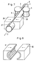
- FIG. 1 shows how a pipe 1 to be provided with a longitudinal weld seam is guided through a laser welding device in the direction of arrow 2.
- a pipe 1 For this purpose, it is first compressed by two rollers 3, 4, which can still be provided with drives, not shown, until the opposite edges of the bent tube touch.
- the gap 5 of the pipe seam will open a little again to form a gap 6 due to the elastic properties of the pipe material.
- the exact position of this gap 6 or the edges of the tube material is now scanned with a sensing roller 7. If the gap 6 is laterally offset, the feeler roller 7 is also laterally offset, thereby pivoting a housing 8 which can be pivoted about the laser light axis 9.
- the laser light beam which is directed downwards axially offset by two deflecting mirrors 10, 11, is also laterally displaced, so that the focused laser beam precisely hits the desired point.
- This welded area then passes between two further rollers 12, 13, the distance between the welding point and these rollers 12, 13 generally being chosen large enough that the material melted by the welding process is no longer plastic.
- the finished weld is shown at 27.
- FIGS. Two types of deflection of the laser beam are shown in FIGS.
- a lower housing part 8 can be seen, which can be pivoted about the axis of the laser light, for example with the aid of bearings 14.
- the laser beam first strikes a plane mirror 10 arranged at 45 ° and then another plane mirror 11, which is also arranged at 45 °.
- the laser light thus deflected twice is then focused by a focusing lens 15. If the housing part 8 is rotated in the direction of the double arrow 16, the focused laser beam describes an arc of a circle with the radius a.
- a plane mirror 10 arranged at 45 ° is also provided.
- the further mirror 11 is a 90 ° parabolic mirror (off-axis mirror), the curvature of which is circular.
- the plane mirror 10 is not oriented at 45 °, but is inclined more towards the laser axis.
- the second mirror 11 is a fully paraboloid mirror. In all three embodiments, however, a laser beam is obtained, which can be pivoted by pivoting the housing 8 on a circular arc piece with the radius a.
- the feeler roller 7 is fastened to a first sliding element 17 which can move in the horizontal direction in the direction of the double arrow 18 and is slidably fastened in a sliding element 19 for this purpose.
- This sliding element 19 in turn can move in the direction of the double arrow 20 in the vertical direction and is slidably attached to a support 21 or the like which extends over the tube 1 for this purpose.
- the parts 17 and 19 form a cross roller table or the like.
- this cross roller guide, cross slide guide or the like the roller 7 by a coil spring 22 down against Workpiece 1 pressed.
- This spring 22 is arranged on a pin 23 and is supported on the housing 8 of the welding head or a part connected thereto.
- This connected part is an element 24 which can execute a movement in the horizontal direction in the direction of the double arrow 25, the exact location in the horizontal direction being determined by an adjusting screw 26. As a result, the original adjustment is possible in order to correctly set the welding head in the transverse direction to the location of the feeler roller 7.
- FIG. 6 Geometric details can also be seen from FIG. 6.
- two further guide rollers 27 and 28 for the tube 1 are also shown in broken lines. All of these pressure rollers or guide rollers are pressed towards one another in the direction of the arrows 29 in the direction of the tube 1.
- the location of the sensing roller is designated by 7, the location at which the focused laser beam strikes the workpiece at 30.
- 31 denotes the axis of rotation for the housing 8, this axis of rotation 31 coinciding with the original axis of the laser light.
- a certain deflection of the sensing roller 7 leads to a somewhat smaller deflection of the focused laser beam 30.
- the mathematical relationship between these deflections can easily be determined with the aid of the radiation set. By changing the location of the stylus roller 7, the corresponding mathematical relationships between stylus deflection and laser beam deflection can still be changed.
- the second pair of pressure rollers 12, 13 is replaced by sliding jaws 28, 29, in which the tube 1 can slide in the direction of the arrow 2.
- sliding jaws 28, 29, ball bush bearings 30, 31 can also be used, which are shown in FIG. 8.
Landscapes
- Physics & Mathematics (AREA)
- Optics & Photonics (AREA)
- Engineering & Computer Science (AREA)
- Plasma & Fusion (AREA)
- Mechanical Engineering (AREA)
- Laser Beam Processing (AREA)
- Length Measuring Devices By Optical Means (AREA)
Claims (10)
- Appareil de soudage au laser pour souder des profilés creux (1) et des profilés plats devant être soudés bord à bord, comportant un dispositif de détection (7) pour l'un ou l'un et l'autre des bords à souder, raccordé aux miroirs de déflexion (10, 11) en vue d'un mouvement pivotant commun, ainsi qu'un dispositif suiveur (7, 10, 11) pour la tête de soudage qui est mobile perpendiculairement à la direction du cordon de soudure et qui présente, pour la lumière laser, des miroirs de déflexion (10, 11) disposés obliquement par rapport à l'axe (9) du faisceau laser et susceptibles de pivoter autour de cet axe (9), caractérisé en ce que le dispositif de détection est réalisé sous forme de palpeur mécanique (7) et en ce que le palpeur (7) s'engage dans une fente réglable (6) entre les bords à souder, définie par des éléments presseurs (3, 4, 12, 13, 28, 29, 30, 31).
- Appareil de soudage au laser selon la revendication 1, caractérisé en ce que les éléments presseurs sont des galets de pression (3, 4, 12, 13).
- Appareil de soudage au laser selon la revendication 1, caractérisé en ce que les éléments presseurs sont constitués par deux galets de pression (3, 4) et deux blocs de glissement (28, 29).
- Appareil de soudage au laser selon la revendication 1, caractérisé en ce que les éléments presseurs sont constitués par des galets de pression (3, 4) et des blocs-paliers à billes (30, 31).
- Appareil de soudage au laser selon l'une quelconque des revendications 1 à 4, caractérise en ce que le palpeur (7) est maintenu dans un guide (19) qui rend possible un mouvement perpendiculaire à la pièce à souder (1).
- Appareil de soudage au laser selon la revendication 5, caractérisé en ce que le palpeur (7) est sollicité élastiquement en direction de la pièce à souder (1).
- Appareil de soudage au laser selon l'une quelconque des revendications 1 à 6, caractérisé en ce que le palpeur (7) est fixé à une table à galets à mouvements croisés ou à un chariot à deux glissières croisées (17, 19).
- Appareil de soudage au laser selon l'une quelconque des revendications 1 à 7, caractérisé en ce qu'il est prévu un guide disposé transversalement par rapport au cordon de soudure (27), comportant un dispositif d'arrêt (26) pour le palpeur (7) ou pour des éléments raccordées à celui-ci.
- Appareil de soudage au laser selon la revendication 7, caractérisé en ce que le dispositif d'arrêt comporte une vis d'ajustage (26).
- Appareil de soudage au laser selon l'une quelconque des revendications 1 à 9, caractérisé en ce que le palpeur est réalisé sous forme de galet palpeur (7).
Applications Claiming Priority (2)
| Application Number | Priority Date | Filing Date | Title |
|---|---|---|---|
| DE8713471U DE8713471U1 (fr) | 1987-10-07 | 1987-10-07 | |
| DE8713471U | 1987-10-07 |
Publications (2)
| Publication Number | Publication Date |
|---|---|
| EP0310793A1 EP0310793A1 (fr) | 1989-04-12 |
| EP0310793B1 true EP0310793B1 (fr) | 1992-02-12 |
Family
ID=6812851
Family Applications (1)
| Application Number | Title | Priority Date | Filing Date |
|---|---|---|---|
| EP88113354A Expired - Lifetime EP0310793B1 (fr) | 1987-10-07 | 1988-08-17 | Appareil de soudage au laser pour souder les profils creux et les profils plats |
Country Status (4)
| Country | Link |
|---|---|
| US (1) | US4839496A (fr) |
| EP (1) | EP0310793B1 (fr) |
| JP (1) | JPH0829427B2 (fr) |
| DE (2) | DE8713471U1 (fr) |
Families Citing this family (26)
| Publication number | Priority date | Publication date | Assignee | Title |
|---|---|---|---|---|
| FR2636554B1 (fr) * | 1988-09-20 | 1992-12-04 | Peugeot | Dispositif de soudage de toles ou analogues par un faisceau laser |
| US5142118A (en) * | 1991-05-14 | 1992-08-25 | Progressive Tool & Industries Co. | Laser welding unit |
| JP2550849Y2 (ja) * | 1991-07-24 | 1997-10-15 | いすゞ自動車株式会社 | レ−ザ−切断機用ノズル |
| JPH06668A (ja) * | 1992-06-19 | 1994-01-11 | Sumitomo Metal Ind Ltd | レーザ溶接装置 |
| DE4419349C1 (de) * | 1994-06-03 | 1996-02-01 | Thyssen Stahl Ag | Aus einem Steg und mindestens einem Flansch durch Strahlungsenergie zusammengeschweißter Profilträger aus Metall, insbesondere Stahl und Verfahren zu seiner Herstellung |
| DE4434134A1 (de) * | 1994-09-24 | 1996-03-28 | Kabelmetal Electro Gmbh | Verfahren zur Herstellung eines längsnahtgeschweißten Metallrohres |
| JP3233542B2 (ja) * | 1995-02-14 | 2001-11-26 | 株式会社オーシーシー | 金属管被覆光ファイバケーブルの製造方法及び製造装置 |
| DE19632021C1 (de) * | 1996-08-08 | 1998-01-02 | Hewing Gmbh | Verfahren zum Ummanteln eines Kunststoffrohres mit einem Metallband und Schweißstation zum Verschweißen der einander überlappenden Längsränder des Metallbandes |
| DE19639667C1 (de) * | 1996-09-27 | 1998-03-12 | Daimler Benz Aerospace Airbus | Verfahren zum Schweißen von Profilen auf großformatigen Aluminium-Strukturbauteilen mittels Laserstrahlen |
| WO1998025727A1 (fr) * | 1996-12-10 | 1998-06-18 | Obschestvo S Ogranichennoi Otvetstvennostju 'lastr' | Procede de fabrication de tubes a soudure longitudinale par soudage laser et dispositif prevu a cet effet |
| EP1060050B1 (fr) | 1998-03-03 | 2003-12-17 | Elpatronic Ag | Procede et dispositif de transfert d'une ebauche a profiles creux |
| DE19847867A1 (de) * | 1998-07-18 | 2000-01-13 | Rofin Sinar Laser Gmbh | Vorrichtung zum Laserschweißen eines Werkstücks entlang einer linienförmigen Naht |
| ES2161113B1 (es) * | 1998-09-07 | 2002-08-01 | Daimler Chrysler Aerospace Air | Maquina de soldar por laser para la soldadura de perfiles sobre componentes estrructurales de gran tamaño. |
| DE10006852C5 (de) * | 2000-02-16 | 2004-08-26 | Anders, Michael, Dr.-Ing. | Verfahren und Vorrichtung zum Fügen von Werkstückteilen mittels eines Energiestrahls, insbesondere Laserstrahls |
| NL1014823C2 (nl) * | 2000-04-03 | 2001-10-04 | Corus Staal Bv | Werkwijze voor het vervaardigen van een buisvormig onderdeel. |
| US20020020164A1 (en) * | 2000-07-26 | 2002-02-21 | Cleveland Bradley A. | Tubular body with deposited features and method of manufacture therefor |
| DE10234242B4 (de) | 2002-07-09 | 2005-10-27 | Airbus Deutschland Gmbh | Anordnung und Verfahren zur Regelung der Nahtlage eines laserstrahlgefügten Profils |
| US20040194275A1 (en) * | 2003-04-02 | 2004-10-07 | Dreistern-Werk Maschinenbau Gmbh & Co. Kg | Method and device for the production of a metal profile |
| KR100965988B1 (ko) | 2003-06-20 | 2010-06-25 | 주식회사 포스코 | 스트립 용접기 헤드유닛의 용접라인 유도장치 |
| DE102004017343A1 (de) * | 2004-04-06 | 2005-11-03 | Muhr Und Bender Kg | Verfahren zur Herstellung von Profilen mit in Längsrichtung veränderlichem Querschnitt |
| ES2306361T3 (es) * | 2005-09-09 | 2008-11-01 | Highyag Lasertechnologie Gmbh | Optica de mecanizado laser guiada de forma tactil. |
| DE102006004919A1 (de) | 2006-02-01 | 2007-08-16 | Thyssenkrupp Steel Ag | Laserstrahlschweißkopf |
| DE102013101276A1 (de) * | 2013-02-08 | 2014-08-14 | Benteler Automobiltechnik Gmbh | Verfahren zur Herstellung eines Kraftfahrzeugstabilisators |
| US10101201B2 (en) * | 2013-11-13 | 2018-10-16 | Medtronic, Inc. | System for continuous laser beam monitoring and analysis |
| DE102017113652A1 (de) * | 2017-06-21 | 2018-12-27 | Photon AG | SYSTEM ZUM LASERSCHWEIßEN UMFASSEND EINE SCHUBVORRICHTUNG, EINE BEARBEITUNGSOPTIK UND MINDESTENS EINE TAKTILE FÜHRVORRICHTUNG |
| EP4039402B1 (fr) * | 2021-02-04 | 2023-08-09 | "SINTUR" Sp. z o.o. | Procédé de soudage d'un tube capillaire et d'un tuyau d'aspiration à l'aide d'une tête laser fibre, et appareil correspondant |
Citations (2)
| Publication number | Priority date | Publication date | Assignee | Title |
|---|---|---|---|---|
| EP1209488A2 (fr) * | 2000-11-27 | 2002-05-29 | Philips Corporate Intellectual Property GmbH | Module détecteur de rayons X |
| EP1208564A1 (fr) * | 1999-09-03 | 2002-05-29 | Dürr Dental GmbH & Co. KG | Dispositif de lecture de feuilles de stockage souples |
Family Cites Families (7)
| Publication number | Priority date | Publication date | Assignee | Title |
|---|---|---|---|---|
| LU66280A1 (fr) * | 1972-10-12 | 1973-08-08 | ||
| US4354090A (en) * | 1979-10-23 | 1982-10-12 | Sws Incorporated | Z-bar guide apparatus and method of butt welding |
| US4436979A (en) * | 1982-05-06 | 1984-03-13 | Sws, Incorporated | Apparatus for continuous laser welding |
| US4577499A (en) * | 1982-11-18 | 1986-03-25 | Cyclomatic Industries, Inc. | Slope-speed sensor for seam welding apparatus |
| JPS62104689A (ja) * | 1984-02-29 | 1987-05-15 | エルパトロ−ニク・アクチエンゲゼルシヤフト | かん円筒部の縦縁をレ−ザ溶接するための装置 |
| FR2583317B1 (fr) * | 1985-06-12 | 1987-09-11 | Carnaud Emballage Sa | Procede de fabrication d'un emballage cylindrique par soudage au moyen d'un faisceau laser et appareil pour la mise en oeuvre d'un tel procede. |
| CH668736A5 (de) * | 1985-07-03 | 1989-01-31 | Weidmueller C A Gmbh Co | Anordnung zur laserbearbeitung eines werkstuecks. |
-
1987
- 1987-10-07 DE DE8713471U patent/DE8713471U1/de not_active Expired
-
1988
- 1988-08-17 EP EP88113354A patent/EP0310793B1/fr not_active Expired - Lifetime
- 1988-08-17 DE DE8888113354T patent/DE3868377D1/de not_active Expired - Lifetime
- 1988-09-29 US US07/251,151 patent/US4839496A/en not_active Expired - Lifetime
- 1988-10-06 JP JP63252861A patent/JPH0829427B2/ja not_active Expired - Fee Related
Patent Citations (2)
| Publication number | Priority date | Publication date | Assignee | Title |
|---|---|---|---|---|
| EP1208564A1 (fr) * | 1999-09-03 | 2002-05-29 | Dürr Dental GmbH & Co. KG | Dispositif de lecture de feuilles de stockage souples |
| EP1209488A2 (fr) * | 2000-11-27 | 2002-05-29 | Philips Corporate Intellectual Property GmbH | Module détecteur de rayons X |
Also Published As
| Publication number | Publication date |
|---|---|
| DE3868377D1 (de) | 1992-03-26 |
| US4839496A (en) | 1989-06-13 |
| DE8713471U1 (fr) | 1987-12-03 |
| JPH01118392A (ja) | 1989-05-10 |
| JPH0829427B2 (ja) | 1996-03-27 |
| EP0310793A1 (fr) | 1989-04-12 |
Similar Documents
| Publication | Publication Date | Title |
|---|---|---|
| EP0310793B1 (fr) | Appareil de soudage au laser pour souder les profils creux et les profils plats | |
| DE3632952C2 (fr) | ||
| EP0284921B1 (fr) | Dispositif pour conduir des rayons optiques | |
| DE19745929C1 (de) | Schweißeinrichtung für zwei über eine in sich geschlossene Schweißnaht miteinander zu verbindende Werkstücke | |
| EP1125672B1 (fr) | Méthode et dispositif pour assembler des pièces au moyen d'un faisceau d'énergie, notamment un faisceau laser | |
| DE60128666T2 (de) | Verfahren und Vorrichtung zum Reibrührschweißen | |
| EP3484656B1 (fr) | Procédé et machine d'usinage au laser pour le soudage au laser d'une section d'une première et d'une seconde pièce | |
| EP0770445A2 (fr) | Méthode de contrÔle et de positionnement d'un faisceau ou d'un jet pour l'usinage d'une pièce | |
| EP1395385B1 (fr) | Procede et dispositif pour la decoupe commandee par robot de pieces a assembler par rayonnement laser | |
| EP2414134B1 (fr) | Dispositif et procédé de découpe au jet d'eau | |
| EP1238746A2 (fr) | Méthode et appareil de découpe et soudage laser à commande robotique | |
| EP2116355A2 (fr) | Dispositif laser doté d'un roue de compression pouvant osciller | |
| EP1131182A1 (fr) | Procede et dispositif pour le soudage de toles avec un laser | |
| EP0266764A2 (fr) | Méthode et dispositif de guidage d'un rayon laser de puissance le long d'un joint | |
| DE3127159A1 (de) | Automatischer kehlnaht-suchmechanismus | |
| EP2056990B1 (fr) | Procédé et dispositif d'usinage de pièces à usiner au moyen d'un rayon laser | |
| DE102021131399A1 (de) | Verfahren und vorrichtung zum aufbringen einer aktiven verbindungskraft beim laserschweissen von sich überlappenden werkstücken | |
| DE19847867A1 (de) | Vorrichtung zum Laserschweißen eines Werkstücks entlang einer linienförmigen Naht | |
| WO2009019145A1 (fr) | Dispositif de soudage doté d'un système mécanique de suivi du cordon | |
| DE102011117454A1 (de) | Laserbearbeitungsvorrichtung | |
| DE10137006A1 (de) | Vorrichtung zur Laserstrahlbearbeitung einer bewegten Materialbahn | |
| DE3444045C2 (de) | Führungsvorrichtung für einen Laserstrahl zur dreidimensionalen Werkstückbearbeitung | |
| DE2359398C3 (de) | Einrichtung in einem Prüfgerät zum Führen einer flächigen Sonde | |
| EP0847548A1 (fr) | Dispositif pour compenser les tolerances de guidage dans des positionneurs multiaxes | |
| DD155306A1 (de) | Einrichtung zum selbsttaetigen fuehren von schweissbrennern auf schweissspaltmitte |
Legal Events
| Date | Code | Title | Description |
|---|---|---|---|
| PUAI | Public reference made under article 153(3) epc to a published international application that has entered the european phase |
Free format text: ORIGINAL CODE: 0009012 |
|
| AK | Designated contracting states |
Kind code of ref document: A1 Designated state(s): BE DE FR GB IT NL |
|
| GBC | Gb: translation of claims filed (gb section 78(7)/1977) | ||
| EL | Fr: translation of claims filed | ||
| ITCL | It: translation for ep claims filed |
Representative=s name: UFFICIO TECNICO ING. A. MANNUCCI |
|
| 17P | Request for examination filed |
Effective date: 19890512 |
|
| 17Q | First examination report despatched |
Effective date: 19900725 |
|
| GRAA | (expected) grant |
Free format text: ORIGINAL CODE: 0009210 |
|
| AK | Designated contracting states |
Kind code of ref document: B1 Designated state(s): BE DE FR GB IT NL |
|
| REF | Corresponds to: |
Ref document number: 3868377 Country of ref document: DE Date of ref document: 19920326 |
|
| ITF | It: translation for a ep patent filed |
Owner name: UFFICIO TECNICO ING. A. MANNUCCI |
|
| ET | Fr: translation filed | ||
| GBT | Gb: translation of ep patent filed (gb section 77(6)(a)/1977) | ||
| PLBE | No opposition filed within time limit |
Free format text: ORIGINAL CODE: 0009261 |
|
| STAA | Information on the status of an ep patent application or granted ep patent |
Free format text: STATUS: NO OPPOSITION FILED WITHIN TIME LIMIT |
|
| 26N | No opposition filed | ||
| PGFP | Annual fee paid to national office [announced via postgrant information from national office to epo] |
Ref country code: BE Payment date: 19970822 Year of fee payment: 10 Ref country code: NL Payment date: 19970822 Year of fee payment: 10 |
|
| PG25 | Lapsed in a contracting state [announced via postgrant information from national office to epo] |
Ref country code: BE Free format text: LAPSE BECAUSE OF NON-PAYMENT OF DUE FEES Effective date: 19980831 |
|
| BERE | Be: lapsed |
Owner name: ROFIN-SINAR LASER G.M.B.H. Effective date: 19980831 |
|
| PG25 | Lapsed in a contracting state [announced via postgrant information from national office to epo] |
Ref country code: NL Free format text: LAPSE BECAUSE OF NON-PAYMENT OF DUE FEES Effective date: 19990301 |
|
| NLV4 | Nl: lapsed or anulled due to non-payment of the annual fee |
Effective date: 19990301 |
|
| REG | Reference to a national code |
Ref country code: GB Ref legal event code: IF02 |
|
| PGFP | Annual fee paid to national office [announced via postgrant information from national office to epo] |
Ref country code: GB Payment date: 20070828 Year of fee payment: 20 |
|
| PGFP | Annual fee paid to national office [announced via postgrant information from national office to epo] |
Ref country code: IT Payment date: 20070827 Year of fee payment: 20 Ref country code: DE Payment date: 20071029 Year of fee payment: 20 |
|
| PGFP | Annual fee paid to national office [announced via postgrant information from national office to epo] |
Ref country code: FR Payment date: 20070821 Year of fee payment: 20 |
|
| REG | Reference to a national code |
Ref country code: GB Ref legal event code: PE20 Expiry date: 20080816 |
|
| PG25 | Lapsed in a contracting state [announced via postgrant information from national office to epo] |
Ref country code: GB Free format text: LAPSE BECAUSE OF EXPIRATION OF PROTECTION Effective date: 20080816 |