EP0310266A2 - Recalibration system for led array - Google Patents
Recalibration system for led array Download PDFInfo
- Publication number
- EP0310266A2 EP0310266A2 EP88308561A EP88308561A EP0310266A2 EP 0310266 A2 EP0310266 A2 EP 0310266A2 EP 88308561 A EP88308561 A EP 88308561A EP 88308561 A EP88308561 A EP 88308561A EP 0310266 A2 EP0310266 A2 EP 0310266A2
- Authority
- EP
- European Patent Office
- Prior art keywords
- illumination
- diodes
- intensity
- memory
- data relating
- Prior art date
- Legal status (The legal status is an assumption and is not a legal conclusion. Google has not performed a legal analysis and makes no representation as to the accuracy of the status listed.)
- Withdrawn
Links
Images
Classifications
-
- G—PHYSICS
- G06—COMPUTING OR CALCULATING; COUNTING
- G06K—GRAPHICAL DATA READING; PRESENTATION OF DATA; RECORD CARRIERS; HANDLING RECORD CARRIERS
- G06K15/00—Arrangements for producing a permanent visual presentation of the output data, e.g. computer output printers
- G06K15/02—Arrangements for producing a permanent visual presentation of the output data, e.g. computer output printers using printers
- G06K15/12—Arrangements for producing a permanent visual presentation of the output data, e.g. computer output printers using printers by photographic printing, e.g. by laser printers
- G06K15/1238—Arrangements for producing a permanent visual presentation of the output data, e.g. computer output printers using printers by photographic printing, e.g. by laser printers simultaneously exposing more than one point
- G06K15/1242—Arrangements for producing a permanent visual presentation of the output data, e.g. computer output printers using printers by photographic printing, e.g. by laser printers simultaneously exposing more than one point on one main scanning line
- G06K15/1247—Arrangements for producing a permanent visual presentation of the output data, e.g. computer output printers using printers by photographic printing, e.g. by laser printers simultaneously exposing more than one point on one main scanning line using an array of light sources, e.g. a linear array
Definitions
- This invention relates to a recalibration system for a light emitting diode (LED) array for use in a print head of a line printer.
- LED light emitting diode
- a print head of a line printer may comprise an array of LED arranged in a line which may be as long as one metre, the line being composed of a tightly packed LED array with each LED providing one pixel of the image to be produced with 600 pixel per inch. It is a known problem that a tight tolerance in uniformity of light output in such a high quality print head is difficult to achieve and even more difficult to maintain. As diodes degrade at different rates, an internal recalibration system is essential to a printer with an expected life > 10,000 hours. Calibration systems are known, see for example US-A-4596995 which require a usual inspection of intensity levels by a human operator; such systems would not be suitable for a recalibration system which can be operated automatically on a daily basis.
- the invention provides a method of automatic recalibration of a print head comprising an array of light emitting diodes (LED) each providing one pixel of an image to be printed, the method comprising :-
- the invention provides apparatus for use in the aforesaid method, the apparatus comprising an array of light emitting diodes (LED) each providing one pixel of an image to be printed, one or more photodetectors for detected the intensity of illumination of the diodes, a memory storing data relating to current levels to be applied to the diodes for illumination thereof, and means for storing data relating to individual intensities of illumination of the diodes, means for determining whether an actual intensity of illumination detected by said photodetectors corresponds with a stored value of intensity of illumination , means for adjusting the current levels to be applied to the diodes, and means for replacing the data stored in memory with data relating to adjusted current levels.
- LED light emitting diodes
- one or more reference diodes are provided, which are normally held in a switched off condition and data is stored in said memory relating to desired current levels to be applied to the one or more reference diodes to achieve desired intensities of illumination and prior to the step (c) of current level adjustment, the desired current level is applied to a reference light emitting diode and it is determined by means of said photodetectors whether the actual intensity of illumination corresponds to the desired intensity of illumination, and if not the current level applied to the reference diode is adjusted until the actual intensity corresponds to the desired intensity, the data stored in memory is replaced with data relating to the adjusted current level to be applied to the reference diode, and the data stored in memory relating to the desired current level to be applied to the LED of the print array is replaced with similarly adjusted current levels.
- a print head 2 for a line printer comprising an aluminium heat sink 4 on which is mounted a central thin film substrate 6 carrying integrated circuits 8 for control of the print head and carrying a central longitudinal array of light emitting diodes 12.
- the diode array is formed as a row of LED chips positioned one adjacent to the other so as to provide a continuous array of light emitting diodes which provide the pixel elements for a complete line of an image to be printed by the printer.
- the LED chips forming the diode array 12 are shown in more detail in our co-pending application (our ref F20424).
- Mounted directly above the diode array is a lens system 18 which consists of a number of short lengths of graded index lenses.
- a number of silicon photodetectors are provided in a slot 20 parallel to the lens 18. Approximately 1 photodetector per inch of diode array length is provided.
- the chips carrying the light emitting diode arrays also contain reference diodes 22 not forming part of the printing mechanism and normally being switched off.
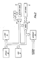
- the control circuitry mounted on the central thin film substrate 6 is shown in figure 2.
- the light emitting diode array 12 is driven by a current driver system 24 which is in turn controlled by a microprocessor control 26.
- the current driver system 24 provides current pulses of modulated width in each duty cycle of operation to the light emitting diode array so as to provide the desired average current to each individual diode.
- Driver system 24 is coupled to receive data from a memory 28 which contains information relating to the desired current levels to be supplied to each individual diode array in terms of the time duration of the current pulses to be applied on each duty cycle.
- a memory 30 contains information relating to the desired illumination level provided by each diode and also corresponding data for the reference diodes.
- Memory 28 is an electrically erasable read only memory and memory 30 is a random access memory (RAM)
- the photodetector array 20 is coupled to a microprocessor control 26 in order to provide data to the control of actual illumination levels provided by the individual diodes of array 12.
- Microprocessor control 26 is operative to compare these actual illumination levels with the desired levels stored in memory 30.
- An external control communicating by an interface 34 is also provided for initiating and controlling a recalibration sequence.
- An amplifier system 36 is provided coupled between photodetector array 20 and analogue to digital converting arrangement 38 for transmitting digital data to the microprocessor control.
- the data stored in memory 28 can be set at the manufacturing stage by consecutively illuminating the individual diodes at a fixed drive current and recording the actual illumination provided by a single external photodetector. These results are then compared with a reference level (which may be the lowest intensity output diode or an integral calibration diode) and all the diodes are then adjusted in drive current by means of the microprocessor control to give the same light output as the reference value by a reprogramming of memory 28 which stores the current values. Thus this gives a bar of uniform light intensity output along it's length. The LED are then individually illuminated and their light output as detected by photodetector array 20 is recorded and stored in memory 30.
- a reference level which may be the lowest intensity output diode or an integral calibration diode
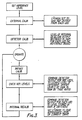
- a recalibration operation is carried out which is shown in figure 3.
- the reference diodes in the LED array which are normally inoperative are switched on and the level of illumination provided by each reference diode is detected by the photodetectors and compared with the desired value stored in memory 30 If these values do not correspond, all the data stored in memory 30 is adjusted by the same ratio in order to take account of the changed conditions applying to the reference diodes, which may be caused by ambient conditions , or amplifier drift.
- each individual diode of the array is illuminated individually in a sequence of steps and for each diode the actual illumination detected is provided by a photodetector arrangement 20 and this actual illumination level is compared with the desired level stored in memory 30. If these two values do not correspond then the current level applied to the diode is adjusted by means of the microprocessor control adjusting the value in memory 28 and then when equality is reached between the desired and actual value of illumination, the adjusted current value for the light emitting diode is stored in memory. When the whole set of diodes has been calibrated, the calibration sequence is completed.
- reference diodes are not normally in use, they will not degrade over a period of time. Normally two reference diodes are provided per chip. If all the reference diodes are employed in a recalibration operation, slight changes in one or two diodes will not have a significant effect.
Landscapes
- Physics & Mathematics (AREA)
- Engineering & Computer Science (AREA)
- Optics & Photonics (AREA)
- General Engineering & Computer Science (AREA)
- General Physics & Mathematics (AREA)
- Theoretical Computer Science (AREA)
- Printers Or Recording Devices Using Electromagnetic And Radiation Means (AREA)
- Facsimile Heads (AREA)
- Tests Of Electronic Circuits (AREA)
- Testing Or Measuring Of Semiconductors Or The Like (AREA)
- Led Device Packages (AREA)
- Led Devices (AREA)
Abstract
Description
- This invention relates to a recalibration system for a light emitting diode (LED) array for use in a print head of a line printer.
- A print head of a line printer may comprise an array of LED arranged in a line which may be as long as one metre, the line being composed of a tightly packed LED array with each LED providing one pixel of the image to be produced with 600 pixel per inch. It is a known problem that a tight tolerance in uniformity of light output in such a high quality print head is difficult to achieve and even more difficult to maintain. As diodes degrade at different rates, an internal recalibration system is essential to a printer with an expected life > 10,000 hours. Calibration systems are known, see for example US-A-4596995 which require a usual inspection of intensity levels by a human operator; such systems would not be suitable for a recalibration system which can be operated automatically on a daily basis.
- In one aspect the invention provides a method of automatic recalibration of a print head comprising an array of light emitting diodes (LED) each providing one pixel of an image to be printed, the method comprising :-
- a) providing one or more photodetectors for detecting the intensity of illumination of the diodes;
- b) storing in memory data relating to individual current levels to be applied to the respective diodes for illumination thereof, and storing in memory data relating to individual intensities of illumination;
- c) for each diode applying the respective current level and detecting the actual intensity of illumination with said one or more photodetectors, determining whether its actual intensity corresponds to the respective stored value of intensity of illumination, and if not adjusting the current level applied to the diode until the actual intensity corresponds with the respective stored value of intensity; and
- d) replacing the data stored in memory with data relating to the adjusted current level.
- In another aspect the invention provides apparatus for use in the aforesaid method, the apparatus comprising an array of light emitting diodes (LED) each providing one pixel of an image to be printed, one or more photodetectors for detected the intensity of illumination of the diodes, a memory storing data relating to current levels to be applied to the diodes for illumination thereof, and means for storing data relating to individual intensities of illumination of the diodes, means for determining whether an actual intensity of illumination detected by said photodetectors corresponds with a stored value of intensity of illumination , means for adjusting the current levels to be applied to the diodes, and means for replacing the data stored in memory with data relating to adjusted current levels.
- As preferred, one or more reference diodes are provided, which are normally held in a switched off condition and data is stored in said memory relating to desired current levels to be applied to the one or more reference diodes to achieve desired intensities of illumination and prior to the step (c) of current level adjustment, the desired current level is applied to a reference light emitting diode and it is determined by means of said photodetectors whether the actual intensity of illumination corresponds to the desired intensity of illumination, and if not the current level applied to the reference diode is adjusted until the actual intensity corresponds to the desired intensity, the data stored in memory is replaced with data relating to the adjusted current level to be applied to the reference diode, and the data stored in memory relating to the desired current level to be applied to the LED of the print array is replaced with similarly adjusted current levels.
- A preferred embodiment of the invention will now be described with reference to the accompanying drawings, wherein:-
- Figure 1 is a perspective schematic view of a print head for a line printer incorporating the present invention;
- Figure 2 is a block diagram of recalibration apparatus in accordance with the invention; and
- Figure 3 is a flow diagram of the various recalibration steps employed in the method of recalibration according to the invention.
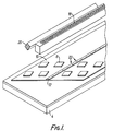
- Referring now to Figure 1 of the drawings there is shown a print head 2 for a line printer comprising an
aluminium heat sink 4 on which is mounted a central thin film substrate 6 carrying integratedcircuits 8 for control of the print head and carrying a central longitudinal array oflight emitting diodes 12. The diode array is formed as a row of LED chips positioned one adjacent to the other so as to provide a continuous array of light emitting diodes which provide the pixel elements for a complete line of an image to be printed by the printer. The LED chips forming thediode array 12 are shown in more detail in our co-pending application (our ref F20424). Mounted directly above the diode array is alens system 18 which consists of a number of short lengths of graded index lenses. A number of silicon photodetectors are provided in aslot 20 parallel to thelens 18. Approximately 1 photodetector per inch of diode array length is provided. The chips carrying the light emitting diode arrays also containreference diodes 22 not forming part of the printing mechanism and normally being switched off. - The control circuitry mounted on the central thin film substrate 6 is shown in figure 2. The light
emitting diode array 12 is driven by acurrent driver system 24 which is in turn controlled by amicroprocessor control 26. Thecurrent driver system 24 provides current pulses of modulated width in each duty cycle of operation to the light emitting diode array so as to provide the desired average current to each individual diode.Driver system 24 is coupled to receive data from amemory 28 which contains information relating to the desired current levels to be supplied to each individual diode array in terms of the time duration of the current pulses to be applied on each duty cycle. Amemory 30 contains information relating to the desired illumination level provided by each diode and also corresponding data for the reference diodes.Memory 28 is an electrically erasable read only memory andmemory 30 is a random access memory (RAM) Thephotodetector array 20 is coupled to amicroprocessor control 26 in order to provide data to the control of actual illumination levels provided by the individual diodes ofarray 12.Microprocessor control 26 is operative to compare these actual illumination levels with the desired levels stored inmemory 30. An external control communicating by aninterface 34 is also provided for initiating and controlling a recalibration sequence. Anamplifier system 36 is provided coupled betweenphotodetector array 20 and analogue todigital converting arrangement 38 for transmitting digital data to the microprocessor control. - The data stored in
memory 28 can be set at the manufacturing stage by consecutively illuminating the individual diodes at a fixed drive current and recording the actual illumination provided by a single external photodetector. These results are then compared with a reference level ( which may be the lowest intensity output diode or an integral calibration diode) and all the diodes are then adjusted in drive current by means of the microprocessor control to give the same light output as the reference value by a reprogramming ofmemory 28 which stores the current values. Thus this gives a bar of uniform light intensity output along it's length.The LED are then individually illuminated and their light output as detected byphotodetector array 20 is recorded and stored inmemory 30. - After a predetermined period of use and at appropriate intervals, say, in the initial warm up period ( perhaps about 15 minutes long) at the beginning of a days work, a recalibration operation is carried out which is shown in figure 3. As an initial step the reference diodes in the LED array which are normally inoperative are switched on and the level of illumination provided by each reference diode is detected by the photodetectors and compared with the desired value stored in
memory 30 If these values do not correspond, all the data stored inmemory 30 is adjusted by the same ratio in order to take account of the changed conditions applying to the reference diodes, which may be caused by ambient conditions , or amplifier drift. - As a next step, each individual diode of the array is illuminated individually in a sequence of steps and for each diode the actual illumination detected is provided by a
photodetector arrangement 20 and this actual illumination level is compared with the desired level stored inmemory 30. If these two values do not correspond then the current level applied to the diode is adjusted by means of the microprocessor control adjusting the value inmemory 28 and then when equality is reached between the desired and actual value of illumination, the adjusted current value for the light emitting diode is stored in memory. When the whole set of diodes has been calibrated, the calibration sequence is completed. - It will be understood that because the reference diodes are not normally in use, they will not degrade over a period of time. Normally two reference diodes are provided per chip. If all the reference diodes are employed in a recalibration operation, slight changes in one or two diodes will not have a significant effect.
Claims (9)
Applications Claiming Priority (2)
| Application Number | Priority Date | Filing Date | Title |
|---|---|---|---|
| GB8722944 | 1987-09-30 | ||
| GB878722944A GB8722944D0 (en) | 1987-09-30 | 1987-09-30 | Calibration system for led array |
Publications (2)
| Publication Number | Publication Date |
|---|---|
| EP0310266A2 true EP0310266A2 (en) | 1989-04-05 |
| EP0310266A3 EP0310266A3 (en) | 1989-06-07 |
Family
ID=10624577
Family Applications (1)
| Application Number | Title | Priority Date | Filing Date |
|---|---|---|---|
| EP88308561A Withdrawn EP0310266A3 (en) | 1987-09-30 | 1988-09-16 | Recalibration system for led array |
Country Status (4)
| Country | Link |
|---|---|
| US (1) | US4857944A (en) |
| EP (1) | EP0310266A3 (en) |
| JP (1) | JPH01158783A (en) |
| GB (1) | GB8722944D0 (en) |
Cited By (12)
| Publication number | Priority date | Publication date | Assignee | Title |
|---|---|---|---|---|
| EP0407065A3 (en) * | 1989-07-07 | 1991-11-27 | Hewlett-Packard Company | Method and apparatus for improving the uniformity of a led printhead |
| EP0434449A3 (en) * | 1989-12-21 | 1992-05-13 | Xerox Corporation | Dynamic equalization for multichannel optical imaging systems |
| EP0419255A3 (en) * | 1989-09-20 | 1993-02-17 | Hewlett-Packard Company | Method and apparatus for controlling apparent uniformity of led printheads |
| EP0529540A3 (en) * | 1991-08-23 | 1993-08-25 | Eastman Kodak Company | Electronic drive circuit for multi-laser thermal printer |
| EP0529530A3 (en) * | 1991-08-23 | 1993-09-01 | Eastman Kodak Company | A method of calibrating a multichannel printer |
| EP0529532A3 (en) * | 1991-08-23 | 1993-09-01 | Eastman Kodak Company | Method and apparatus for the calibration of a multichannel printer |
| WO1994004994A1 (en) * | 1992-08-24 | 1994-03-03 | Siemens Aktiengesellschaft | Arrangement for the simultaneous control of a plurality of luminescent diodes |
| GB2316365A (en) * | 1996-08-14 | 1998-02-25 | Oki Data Kk | LED or thermal printhead having correction data entered after manufacture |
| EP0965456A1 (en) * | 1998-06-16 | 1999-12-22 | Noritsu Koki Co., Ltd. | Method and apparatus for detecting positions of light emitting elements |
| DE10028141C1 (en) * | 2000-06-07 | 2002-03-14 | Siemens Ag | Method and device for controlling lighting units in an optical monitoring system |
| WO2002045007A1 (en) * | 2000-11-28 | 2002-06-06 | Coherent, Inc. | Printer head with linear array of individually addressable diode-lasers |
| EP1326198A3 (en) * | 2001-12-26 | 2004-05-12 | Xerox Corporation | Illumination detection method and apparatus for led printbars |
Families Citing this family (18)
| Publication number | Priority date | Publication date | Assignee | Title |
|---|---|---|---|---|
| US4952949A (en) * | 1989-11-28 | 1990-08-28 | Hewlett-Packard Company | LED printhead temperature compensation |
| JPH03244166A (en) * | 1990-02-22 | 1991-10-30 | Hitachi Ltd | Light-emitting element driving circuit |
| JP3323324B2 (en) * | 1993-06-18 | 2002-09-09 | 株式会社リコー | Light emitting diode and light emitting diode array |
| JPH07202263A (en) * | 1993-12-28 | 1995-08-04 | Ricoh Co Ltd | Edge emitting type light emitting diode, array type light source, side receiving type light receiving element, light receiving and emitting element, edge emitting type light emitting diode array type light source |
| US5666150A (en) * | 1993-12-29 | 1997-09-09 | Eastman Kodak Company | Non-uniformity correction for LED printhead in electrophotographic gray scale printing |
| US5774165A (en) * | 1994-09-22 | 1998-06-30 | Oki Electric Industry Co., Ltd. | Light emission intensity width compensating method of LED print head and apparatus thereof |
| US5699103A (en) * | 1994-12-20 | 1997-12-16 | Eastman Kodak Company | Method for producing a calibrated array of light-emitting diodes and apparatus including the calibrated array |
| JP3887713B2 (en) * | 1997-06-18 | 2007-02-28 | 双葉電子工業株式会社 | Optical printer |
| US6197576B1 (en) * | 1998-05-22 | 2001-03-06 | Gideon Eden | Instrument for detection of microorganisms |
| JP2000033731A (en) * | 1998-07-17 | 2000-02-02 | Citizen Watch Co Ltd | Calibration device of light emitting element in optical printer |
| AU7730800A (en) | 1999-09-29 | 2001-04-30 | Color Kinetics Incorporated | Systems and methods for calibrating light output by light-emitting diodes |
| JP2001096803A (en) * | 1999-10-04 | 2001-04-10 | Fujitsu Ltd | Exposure apparatus, image forming apparatus, and method of manufacturing exposure apparatus |
| US7023543B2 (en) | 2002-08-01 | 2006-04-04 | Cunningham David W | Method for controlling the luminous flux spectrum of a lighting fixture |
| US20050030192A1 (en) * | 2003-08-08 | 2005-02-10 | Weaver James T. | Power supply for LED airfield lighting |
| US20050157160A1 (en) * | 2004-01-21 | 2005-07-21 | Xerox Corporation | Parallel beam to beam uniformity correction |
| US20100007588A1 (en) * | 2008-07-09 | 2010-01-14 | Adaptive Micro Systems Llc | System and method for led degradation and temperature compensation |
| US20120119661A1 (en) * | 2009-11-25 | 2012-05-17 | Delo Industrial Adhesives Llc | Light emitting diode operating device and method |
| WO2020242498A1 (en) | 2019-05-31 | 2020-12-03 | Hewlett-Packard Development Company, L.P. | Adjusting print apparatus light sources |
Family Cites Families (9)
| Publication number | Priority date | Publication date | Assignee | Title |
|---|---|---|---|---|
| US4455562A (en) * | 1981-08-14 | 1984-06-19 | Pitney Bowes Inc. | Control of a light emitting diode array |
| JPS606473A (en) * | 1983-06-24 | 1985-01-14 | Canon Inc | printer head drive device |
| JPH0764096B2 (en) * | 1983-06-24 | 1995-07-12 | キヤノン株式会社 | Recording device |
| DE3438949C2 (en) * | 1983-10-25 | 1994-03-10 | Canon Kk | Printing device |
| US4588883A (en) * | 1983-11-18 | 1986-05-13 | Eastman Kodak Company | Monolithic devices formed with an array of light emitting diodes and a detector |
| US4651176A (en) * | 1984-04-25 | 1987-03-17 | Canon Kabushiki Kaisha | Optical printer head and printer using same |
| JPS61206274A (en) * | 1985-03-08 | 1986-09-12 | Toshiba Corp | Optical measuring circuit for semiconductor light emitting device |
| DE3534338A1 (en) * | 1985-09-26 | 1987-04-02 | Siemens Ag | ELECTROPHOTOGRAPHIC PRINTER WITH AN EXPOSURE ENERGY / CORRECTION DEVICE FOR THE OPTICAL CHARACTER GENERATOR |
| JPS62108586A (en) * | 1985-11-06 | 1987-05-19 | Matsushita Graphic Commun Syst Inc | Compensator for dispersion of amount of light from led array |
-
1987
- 1987-09-30 GB GB878722944A patent/GB8722944D0/en active Pending
-
1988
- 1988-09-16 EP EP88308561A patent/EP0310266A3/en not_active Withdrawn
- 1988-09-29 JP JP63245847A patent/JPH01158783A/en active Pending
- 1988-09-30 US US07/251,497 patent/US4857944A/en not_active Expired - Fee Related
Cited By (16)
| Publication number | Priority date | Publication date | Assignee | Title |
|---|---|---|---|---|
| EP0407065A3 (en) * | 1989-07-07 | 1991-11-27 | Hewlett-Packard Company | Method and apparatus for improving the uniformity of a led printhead |
| EP0419255A3 (en) * | 1989-09-20 | 1993-02-17 | Hewlett-Packard Company | Method and apparatus for controlling apparent uniformity of led printheads |
| EP0434449A3 (en) * | 1989-12-21 | 1992-05-13 | Xerox Corporation | Dynamic equalization for multichannel optical imaging systems |
| EP0529540A3 (en) * | 1991-08-23 | 1993-08-25 | Eastman Kodak Company | Electronic drive circuit for multi-laser thermal printer |
| EP0529530A3 (en) * | 1991-08-23 | 1993-09-01 | Eastman Kodak Company | A method of calibrating a multichannel printer |
| EP0529532A3 (en) * | 1991-08-23 | 1993-09-01 | Eastman Kodak Company | Method and apparatus for the calibration of a multichannel printer |
| WO1994004994A1 (en) * | 1992-08-24 | 1994-03-03 | Siemens Aktiengesellschaft | Arrangement for the simultaneous control of a plurality of luminescent diodes |
| GB2316365B (en) * | 1996-08-14 | 1999-11-17 | Oki Data Kk | Print head for a printer |
| GB2316365A (en) * | 1996-08-14 | 1998-02-25 | Oki Data Kk | LED or thermal printhead having correction data entered after manufacture |
| EP0965456A1 (en) * | 1998-06-16 | 1999-12-22 | Noritsu Koki Co., Ltd. | Method and apparatus for detecting positions of light emitting elements |
| US6337738B1 (en) | 1998-06-16 | 2002-01-08 | Noritsu Koki Co., Ltd. | Method and apparatus for detecting positions of light emitting elements |
| DE10028141C1 (en) * | 2000-06-07 | 2002-03-14 | Siemens Ag | Method and device for controlling lighting units in an optical monitoring system |
| WO2002045007A1 (en) * | 2000-11-28 | 2002-06-06 | Coherent, Inc. | Printer head with linear array of individually addressable diode-lasers |
| US6603498B1 (en) | 2000-11-28 | 2003-08-05 | Coherent, Inc. | Printer head with linear array of individually addressable diode-lasers |
| EP1326198A3 (en) * | 2001-12-26 | 2004-05-12 | Xerox Corporation | Illumination detection method and apparatus for led printbars |
| US6828538B2 (en) | 2001-12-26 | 2004-12-07 | Xerox Corporation | Illumination detection method for LED printbars |
Also Published As
| Publication number | Publication date |
|---|---|
| JPH01158783A (en) | 1989-06-21 |
| EP0310266A3 (en) | 1989-06-07 |
| GB8722944D0 (en) | 1987-11-04 |
| US4857944A (en) | 1989-08-15 |
Similar Documents
| Publication | Publication Date | Title |
|---|---|---|
| US4857944A (en) | Recalibration system for LED array | |
| EP0529540B1 (en) | Electronic drive circuit for multi-laser thermal printer | |
| US4780731A (en) | Electrophotographic printer comprising an exposure energy correcting means for the optical character generator | |
| US4897639A (en) | Image forming method and apparatus | |
| US6329758B1 (en) | LED matrix display with intensity and color matching of the pixels | |
| US6081073A (en) | Matrix display with matched solid-state pixels | |
| US5016027A (en) | Light output power monitor for a LED printhead | |
| EP1326198B1 (en) | Illumination detection method and apparatus for led printbars | |
| EP0260574A2 (en) | Printing head | |
| US5200765A (en) | Apparatus and method for calibrating a grey level printhead | |
| EP0864430A1 (en) | Aligner, exposure method and printer | |
| EP0419255A2 (en) | Method and apparatus for controlling apparent uniformity of led printheads | |
| EP3655818A1 (en) | Method of controlling a segmented flash system | |
| US20010038268A1 (en) | Device for the ecpoaure of photographic recording material | |
| US6870558B2 (en) | Optical fixing unit, illuminance correcting method for the same, and thermal printer | |
| JPS62108586A (en) | Compensator for dispersion of amount of light from led array | |
| US7242416B2 (en) | Optical head | |
| US20050068411A1 (en) | Methods and apparatus for driving illuminators in printing applications | |
| JP4637650B2 (en) | Exposure apparatus and gradation correction method in exposure apparatus | |
| JPH06297769A (en) | Led print head | |
| JPH07214819A (en) | Exposure system using LED array | |
| JP4660389B2 (en) | Exposure equipment | |
| JP4637712B2 (en) | Exposure equipment | |
| JPS63222869A (en) | Image forming method | |
| EP1607902B1 (en) | Adjustment of exposure power in a LED printer |
Legal Events
| Date | Code | Title | Description |
|---|---|---|---|
| PUAI | Public reference made under article 153(3) epc to a published international application that has entered the european phase |
Free format text: ORIGINAL CODE: 0009012 |
|
| AK | Designated contracting states |
Kind code of ref document: A2 Designated state(s): BE DE FR GB IT NL |
|
| PUAL | Search report despatched |
Free format text: ORIGINAL CODE: 0009013 |
|
| AK | Designated contracting states |
Kind code of ref document: A3 Designated state(s): BE DE FR GB IT NL |
|
| 17P | Request for examination filed |
Effective date: 19891114 |
|
| 17Q | First examination report despatched |
Effective date: 19901108 |
|
| RAP1 | Party data changed (applicant data changed or rights of an application transferred) |
Owner name: PRP OPTOELECTRONICS LIMITED |
|
| STAA | Information on the status of an ep patent application or granted ep patent |
Free format text: STATUS: THE APPLICATION IS DEEMED TO BE WITHDRAWN |
|
| 18D | Application deemed to be withdrawn |
Effective date: 19910522 |