EP0864430A1 - Aligner, exposure method and printer - Google Patents
Aligner, exposure method and printer Download PDFInfo
- Publication number
- EP0864430A1 EP0864430A1 EP97929550A EP97929550A EP0864430A1 EP 0864430 A1 EP0864430 A1 EP 0864430A1 EP 97929550 A EP97929550 A EP 97929550A EP 97929550 A EP97929550 A EP 97929550A EP 0864430 A1 EP0864430 A1 EP 0864430A1
- Authority
- EP
- European Patent Office
- Prior art keywords
- gradation
- light
- exposure
- control portion
- gradation level
- Prior art date
- Legal status (The legal status is an assumption and is not a legal conclusion. Google has not performed a legal analysis and makes no representation as to the accuracy of the status listed.)
- Withdrawn
Links
Images


Classifications
-
- B—PERFORMING OPERATIONS; TRANSPORTING
- B41—PRINTING; LINING MACHINES; TYPEWRITERS; STAMPS
- B41J—TYPEWRITERS; SELECTIVE PRINTING MECHANISMS, i.e. MECHANISMS PRINTING OTHERWISE THAN FROM A FORME; CORRECTION OF TYPOGRAPHICAL ERRORS
- B41J19/00—Character- or line-spacing mechanisms
- B41J19/18—Character-spacing or back-spacing mechanisms; Carriage return or release devices therefor
- B41J19/20—Positive-feed character-spacing mechanisms
-
- B—PERFORMING OPERATIONS; TRANSPORTING
- B41—PRINTING; LINING MACHINES; TYPEWRITERS; STAMPS
- B41J—TYPEWRITERS; SELECTIVE PRINTING MECHANISMS, i.e. MECHANISMS PRINTING OTHERWISE THAN FROM A FORME; CORRECTION OF TYPOGRAPHICAL ERRORS
- B41J2/00—Typewriters or selective printing mechanisms characterised by the printing or marking process for which they are designed
- B41J2/435—Typewriters or selective printing mechanisms characterised by the printing or marking process for which they are designed characterised by selective application of radiation to a printing material or impression-transfer material
- B41J2/447—Typewriters or selective printing mechanisms characterised by the printing or marking process for which they are designed characterised by selective application of radiation to a printing material or impression-transfer material using arrays of radiation sources
- B41J2/45—Typewriters or selective printing mechanisms characterised by the printing or marking process for which they are designed characterised by selective application of radiation to a printing material or impression-transfer material using arrays of radiation sources using light-emitting diode [LED] or laser arrays
-
- B—PERFORMING OPERATIONS; TRANSPORTING
- B41—PRINTING; LINING MACHINES; TYPEWRITERS; STAMPS
- B41J—TYPEWRITERS; SELECTIVE PRINTING MECHANISMS, i.e. MECHANISMS PRINTING OTHERWISE THAN FROM A FORME; CORRECTION OF TYPOGRAPHICAL ERRORS
- B41J2/00—Typewriters or selective printing mechanisms characterised by the printing or marking process for which they are designed
- B41J2/52—Arrangement for printing a discrete number of tones, not covered by group B41J2/205, e.g. applicable to two or more kinds of printing or marking process
-
- H—ELECTRICITY
- H04—ELECTRIC COMMUNICATION TECHNIQUE
- H04N—PICTORIAL COMMUNICATION, e.g. TELEVISION
- H04N1/00—Scanning, transmission or reproduction of documents or the like, e.g. facsimile transmission; Details thereof
- H04N1/40—Picture signal circuits
- H04N1/40025—Circuits exciting or modulating particular heads for reproducing continuous tone value scales
- H04N1/40043—Circuits exciting or modulating particular heads for reproducing continuous tone value scales using more than one type of modulation, e.g. pulse width modulation and amplitude modulation
-
- H—ELECTRICITY
- H04—ELECTRIC COMMUNICATION TECHNIQUE
- H04N—PICTORIAL COMMUNICATION, e.g. TELEVISION
- H04N1/00—Scanning, transmission or reproduction of documents or the like, e.g. facsimile transmission; Details thereof
- H04N1/40—Picture signal circuits
- H04N1/40025—Circuits exciting or modulating particular heads for reproducing continuous tone value scales
- H04N1/4005—Circuits exciting or modulating particular heads for reproducing continuous tone value scales with regulating circuits, e.g. dependent upon ambient temperature or feedback control
Definitions
- the present invention relates to an exposure apparatus, an exposure method and a printing apparatus that are capable of forming an image on a photosensitive sheet such as a Cycolor medium.
- a method for forming a color photograph or a color print there is a method for forming an image, such as a picture or a character, on a photosensitive sheet by exposing the sheet.
- photosensitive sheets for example, a photosensitive sheet employing a multi-layer color development method, in which sheet three or more layers of photosensitive emulsions with different color sensitivities are layered on a single supportive sheet thus forming a photosensitive member, a photosensitive sheet that employs a film in which each emulsion layer contains a pigment and a developing agent so that the film is capable of being exposed and developed simultaneously, and the like.
- a still another photosensitive sheet is a so-called Cycolor medium, which employs, as a photosensitive material, microcapsules (cyliths) that contain a chromogenic substance and a photoinitiator.
- Cycolor medium a thin supportive body formed from, for example, polyester, is coated with numerous cyliths of a very small size. When exposed to light, cyliths harden so that only the cyliths of a specific color are activated, and the cyliths are ruptured by pressurization, thereby forming a predetermined image of a specific color.
- Other photosensitive sheets have different color development principles, but are exposed to light of the color of an image or its complementary color to form an image.
- LEDs or the like as light sources (light-emitting elements) for individual colors allows a compact construction of the light sources. Furthermore, provision of the light sources for individual colors enables control of exposure duration, brightness and the like.
- a design has been considered in which the exposure duration and brightness can be set appropriately for each color, whereby it will become possible to form images with good color balance and reduced color distortion on a medium in which the photosensitive materials have different exposure characteristics to different colors.
- a printing apparatus 10 as shown in Fig. 1, equipped with an exposure apparatus having LEDs or lasers as light-emitting elements, has been developed.
- an exposure head 15 is mounted on a carriage 13, and the carriage 13 is moved along a shaft 12 in scanning directions X.
- the photosensitive sheet 1 is thereby moved relative to the light-emitting elements of the exposure head 15, so that the entire photosensitive sheet is exposed to light from the LEDs or lasers of the exposure head 15 to form an image.
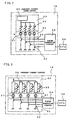
- Fig. 2 shows an example of the arrangement of the exposure head 15, especially relating to the exposure head 15 having LEDs 31 for red color (R).
- exposure is performed by light-emitting sources 21 each having four LEDs 31 for a single color.
- Each LED 31 of the light-emitting source 21 emits light when power is supplied thereto from a power supplying circuit 23.
- the light emitting duration (exposure duration) of each LED 31 is controllable by a switching circuit 22.
- the power supplying circuit 23 has a constant voltage power source 34, and semi-fixed resistors 33 for setting the power supplied to the corresponding LEDs 31 in accordance with the brightness of the corresponding LEDs 31.
- the semi-fixed resistors 33 are adjusted so that the brightness of the red (R), green (G) and blue (B) light emitting sources become predetermined values at the time of shipment.
- the individual variation of LEDs is large and the variation in amount of light emission (brightness) is large, and many photosensitive sheets have different sensitivities depending on wavelengths. Therefore, the semi-fixed resistors 33 are provided in the power supplying circuit 23 to set power supplied to each LED in accordance with the variations of LEDs and basic characteristics of photosensitive sheets depending on wavelengths.
- a transistor switch 32 is provided for each LED 31.
- a CPU 25 controls a timing generating circuit 24 on the basis of pixel gradation information.
- Each transistor switch 32 is turned on and off by a signal from the timing generating circuit 24. Therefore, the duration of power supply to each LED 31 is controlled by the signal from the timing generating circuit 24, so that the duration of exposure of a photosensitive sheet can be controlled separately for each color and each LED 31.
- the exposure head 15 shown in Fig. 2 is able to absorb or offset the individual variations of the LEDs by using the semi-fixed resistors. Therefore, it is possible to provide initial settings in accordance with the basic characteristics of a photosensitive sheet to be exposed.
- the forward voltage of the LEDs 31 and the voltage between the collector and emitter of each transistor switch 32 changes depending on temperature, the value of drive current supplied to the LEDs 31 changes with changes in ambient temperature or operating conditions of the exposure head 15. As a result, the color tone of an image formed by exposure may vary or uneven color development may occur, depending on the operating conditions.
- Fig. 3 shows another example of the exposure head 15 having LEDs.
- constant current circuits 35 are provided in a power supplying circuit 23 corresponding to LEDs 31 provided in a light emitting source 21, so that the initial setting of the current to be supplied to the LEDs 31 from the constant current circuits 35 can be made using the semi-fixed resistors 33. Therefore, a constant current is supplied to each LED 31 despite changes in temperature depending on operating conditions, so that images with relatively stable color tones can be obtained.
- the semi-fixed resistors provided in the same number as that of the LEDs, are adjusted at a timing when the initial setting of the semi-fixed resistors is possible, such as at the time of shipment. Once adjusted, the semi-fixed resistors cannot be re-adjusted.
- this exposure head 15 also requires that the duration of exposure by the LEDs be changed by controlling the switching circuit 22 during operation of the printing apparatus to achieve corrections for changes in brightness of LEDs and the like.
- the duration of exposure by LEDs is controlled by the switching circuit 22, the CPU 25 and the timing generating circuit 24, and can be used as a basis for corrections for changes in printing environments and gradation control if the gradation level is as low as about several tens of gradation increments.
- graduation control at a level of about 256-1024 gradation increments is recently required, a control mechanism with a resolution higher than the graduation level is needed in order to perform gradation control and corrections for changes in brightness and the like on the basis of exposure duration. Therefore, the control mechanism, the exposure head and the printing apparatus become very expensive. As the gradation level increases, such cost increases become greater.
- the exposure duration per exposure cycle of a single dot becomes short when, for example, the LED brightness is increased. Therefore, if the gradation level becomes high, it becomes impossible to secure a sufficient resolution in the direction of the time axis for graduation control, so that sufficient graduation expression cannot be obtained. Then, various problems arise. That is, if the correction is simplified in order to obtain sufficient gradation expression, the image resolution decreases depending on temperature or the sensitivity of photosensitive sheets. Conversely, if the gradation level control is simplified, desired color expression may not be obtained. It is possible to increase the exposure duration in order to secure a certain resolution. However, an increase in exposure duration per dot will considerably increase the time required for printing.
- an object of the invention to provide an exposure apparatus, an exposure method and a printing apparatus that always allow easy correction for changes in environmental conditions that include temperature regarding light-emitting elements, such as LEDs, sensitivity of photosensitive sheets, and, in addition to correction for changes in environmental conditions, provide sufficient gradation expression. It is an another object of the invention to make it possible to provide an exposure apparatus and a printing apparatus that have a function for correction regarding environmental conditions and a function capable of gradation expression at a high gradation level. It is still an another object of the invention to provide an exposure apparatus and a printing apparatus that perform printing with high image quality without requiring expensive LEDs or a photosensitive sheet which have stable characteristics.
- a power control portion capable of dynamically changing the power supplied to light-emitting elements by controlling the current or voltage supplied to the light-emitting elements, and a time control portion capable of dynamically changing and controlling the exposure duration are provided. Therefore, one of the power control portion and the time control portion performs gradation display, and the other corrects exposure conditions for environmental changes.
- the time control portion is used for the gradation expression
- the power control portion is used for the correction, so that corrections regarding variations in temperature or the sensitivity of photosensitive sheets can be performed without reducing the resolution needed for the gradation expression.
- the exposure apparatus of the invention is characterized by comprising: a light-emitting element that emits light for exposure of a photosensitive sheet; a power control portion capable of controlling current or voltage or both to be supplied to the light-emitting element; and a time control portion capable of controlling duration of exposure by the light-emitting element, one of the power control portion and the time control portion performing gradation expression of an image formed on the photosensitive sheet, and the other one performing correction of an exposure condition in accordance with an environmental change at the time of exposure.
- the time control portion allows easy employment of switching control, so that a high resolution can be obtained. Therefore, it is preferable to use the time control portion to perform the gradation display and use the power control portion to perform the correction in accordance with changes in printing environments. If the correction in accordance with environmental changes is performed separately from the gradation display, the control portion for the gradation display, for example, the time control portion, has a reduced control load. Therefore, it is possible to employ simple circuits whose resolution is not so very high, in the time control portion, which circuits can be obtained at low costs.
- the power control portion is able to maintain constant brightness of the light-emitting elements by correcting for changes in characteristics of the light-emitting elements depending on temperature changes. It is also possible to change the brightness of the light-emitting elements to cope with lot variations of photosensitive sheets or changes in photosensitive sheet sensitivity due to temperature changes.
- the power control portion controlling the brightness of the light-emitting elements. Since all the exposure conditions that require correction depending on changes in printing environments can be adjusted by dynamically changing the brightness of the light-emitting elements in the manner described above, the time control portion only needs to control the exposure duration on the basis of gradation information. Therefore, the resolution of the side of gradation control is free from the burden of correction regarding environmental conditions, but time can be fully utilized on the gradation control side so that a high resolution for gradation expression can be reliably provided. Further, it becomes unnecessary to provide the time control portion with a resolution that is higher than the resolution required in order to reproduce image data.
- the exposure apparatus of the invention is able to print high-quality multi-gradation images using a small-size simple time control portion. Therefore, using the exposure apparatus of the invention, it becomes possible to provide a low-price, small-size printing apparatus capable of printing an image expressed with multi-gradations.
- the exposure apparatus of the invention further comprises: a set value control portion capable of changing a value of current or voltage to be supplied from the power control portion to the light-emitting element; a temperature sensor that detects a temperature in the vicinity of the light-emitting element; and a memory capable of storing data regarding and the direct or indirect value of current or voltage supplied to the light-emitting element when brightness of the light-emitting element is corrected and a temperature at that time, wherein the set value control portion controls the value of current or voltage to be supplied to the light-emitting element, on the basis of data in the memory and the temperature detected by the temperature sensor.
- An input portion capable of inputting information regarding sensitivity of the photosensitive sheet may also be provided, so that a set value control portion corrects the value of current or voltage to be supplied to the light-emitting element on the basis of the information regarding sensitivity of the photosensitive sheet. Therefore, it becomes possible to correct exposure conditions for variation in photosensitive sheet sensitivity. Since the value of current or voltage and the temperature at the time of the correction are stored in the memory, the initial setting of exposure conditions can be easily performed. Furthermore, it also becomes possible to correct the exposure conditions by updating the data in the memory during use.
- the exposure apparatus described above is able to perform correction of exposure conditions and gradation control using an exposure method comprising the following steps:
- the second step it is also possible to correct the current or voltage to be supplied to the light-emitting element in accordance with the information regarding the sensitivity of a photosensitive sheet or user's taste of lightness or color tone.
- This exposure method may be provided as a logic circuit in the form of hardware, or may be provided in the form of software for controlling a microcomputer or the like, which is installed in a memory medium, such as a ROM, that can be readable by a computer.
- the exposure apparatus of the invention is able to dynamically perform correction of exposure conditions based on changes in environments, such as temperature, photosensitive sheet sensitivity variation and the like, and is able to secure a resolution required for gradation control without using an expensive control mechanism. Therefore, using a printing apparatus comprising the exposure apparatus of the invention and a conveying apparatus that conveys at least one of a photosensitive sheet and the exposure apparatus at a predetermined timing relative to each other, it is possible to provide a low-price, small-size printing apparatus capable of printing color images with stable high quality without being affected by variations in temperature or photosensitive sheet sensitivity.
- a plurality of groups of light-emitting elements are assigned to a color and a plurality of groups of light-emitting elements are used to display or express gradations, it is preferable to control light emission of the light-emitting elements at substantially equal duties.
- each group of light-emitting elements are controlled with a high resolution of, for example, 1000 gradations, the hardware cost becomes very high.
- the gradation level of the individual light-emitting elements (light sources), such as LEDs) of the plurality of groups is cyclically changed in accordance with the total gradation level of exposure of each dot. In this manner, the gradation level required for control of each groups of light-emitting elements can be reduced, and the light-emitting elements of all the groups can be turned on at substantially equal duties.
- an exposure apparatus is characterized by further comprising: a plurality m of groups of the light-emitting elements (light sources), and a gradation control portion capable of setting a gradation level for gradation expression using one of the power control portion and the time control portion, the gradation control portion having a main gradation level control potion to which gradation information capable of instructing a gradation level whose maximum is an integer n is inputted, and m number of gradation level setting portions into which l number of gradation levels, wherein l is an integer equal to or greater than an integer obtained by dividing the integer n by the integer m, can be set with respect to each group of the light-emitting elements, wherein the main gradation level control portion sets a gradation level j + 1 which is higher by 1 than a gradation level j, into gradation level setting portions pre-set within a kth position, and sets the gradation level j into the other gradation level
- a resolution of about 1000 gradation levels may be achieved by providing a main gradation level control portion to which 10-bit gradation information capable of instructing about 1000 gradation levels is inputted, and four 8-bit gradation level setting portions into which 256 gradation levels can be set with respect to each of the four light-emitting elements.
- the main gradation level control portion sets the higher 8 bits of gradation information, that is, an integer obtained by dividing the 10-bit gradation information by 4, into the gradation level setting portions, and 1 is added to the value of the gradation level setting portions corresponding to the lower 2 bits of the gradation information, that is, the value of a remainder obtained through the division of the 10-bit gradation information by 4. Then the light-emitting elements are turned on in accordance with the values of the corresponding gradation level setting portions.
- gradation levels are set in the time control portion using the gradation control portion, it is possible to duty-control the individual light-emitting elements on the basis of the values of the corresponding gradation level setting portions. Further, if the duration of exposure by the individual groups of light-emitting elements is cyclically changed at 8-bit gradation levels, the duration of exposure by all the light sources has a resolution corresponding to 10-bit gradation information.
- the light-emitting elements pre-set within the kth position among m number of groups of light-emitting elements are caused to emit light at a gradation level j + 1 which is higher by 1 than a gradation level j, and the other light-emitting elements are caused to emit light at the gradation level j, wherein j is an integer obtained by division of a gradation level i, instructed for a certain dot, by the integer m, and k is a remainder obtained by that division.
- an exposure method for forming an image by scanning individual dots with light emitted from four groups of light-emitting elements for each color is characterized in that when exposure duration is set in the above-described third step and the light-emitting elements are turned on in the fourth step, the following steps are repeatedly performed:
- the exposure method comprising the above-described steps may be provided as a logic circuit in the form of hardware, and may also be provided in the form of software for controlling a microcomputer, which software is installed in a ROM or the like.
- Fig. 1 is a diagram schematically illustrating a construction of a printing apparatus that exposes a photosensitive using LEDs as light-emitting elements.
- Fig. 2 is a diagram illustrating an example of the exposure apparatus having a function of adjusting variations in LED brightness.
- Fig. 3 is a diagram illustrating another example of the exposure apparatus having a function of adjusting variations in LED brightness.
- Fig. 4 is a block diagram schematically illustrating a construction of a printer according to the invention.
- Fig. 5 is a flowchart illustrating an exposure method wherein the power control of the printer shown in Fig. 4 is performed.
- Fig. 6 is a block diagram schematically illustrating a timing generating circuit of a printer according to the invention.
- Fig. 7 shows control states of four LEDs at the time of exposure performed by gradation control of one of the LEDs.
- Fig. 8 is a graph indicating the characteristics of amount of exposure where the control method indicated in Fig. 7 is employed.
- Fig. 9 is a flowchart illustrating an exposure method wherein the timing generating circuit shown in Fig. 6 is employed.
- Fig. 10 shows control states of LEDs based on the exposure method illustrated in Fig. 9.
- Fig. 11 is a graph indicating the characteristics of amount of exposure by the control method illustrated in Fig. 9.
- Fig. 4 shows a block diagram of a printing apparatus 10 according to the invention.
- the general construction of the printing apparatus (printer) 10 is substantially the same as that shown in Fig. 1.
- An exposure head 15 is mounted on a carriage 13 which is moved relative to a photosensitive medium 1 in scanning directions X.
- the medium 1 is conveyed in a sheet conveying direction Y perpendicular to the scanning directions X. Therefore, the exposure head 15 is operated over the entire medium 1 to form an image.
- the printer 10 of this embodiment is designed to be generally controlled by a CPU 25, that is, a central processing unit. Under control of the CPU 25, the exposure head 15 and the photosensitive print sheet (medium) 1 are moved in accordance with the exposure cycle of exposure of individual dots on the medium 1.
- the CPU 25 has a function of controlling a sheet conveying roller 11 through a sheet conveyance control portion 17, and a function of controlling a carriage motor 14 for reciprocating the carriage 13 along a shaft 12 in the scanning directions X through a carriage control portion 18.
- the CPU 25 further has a function of receiving image data, including gradation data, from a host apparatus, such as a personal computer, via a buffer 19, and exposing the medium 1 by controlling the exposure head 15 on the basis of the image data received.
- An exposure apparatus 20 of this embodiment employs LEDs 31 as light-emitting elements.
- the exposure apparatus 20 has light source units 29R, 29G, 29B that are provided with a plurality (four in this embodiment) of LEDs 31 of three primary colors (red (R), green (G) and blue (B) in this embodiment, but cyan, magenta and yellow are also possible), respectively. Since the light source units 29R, 29G and 29B have the same construction, the red light source 29R will be described below as a representative.
- the light source unit 29R has a light-emitting source 21 having four LEDs 31 as light-emitting elements, a power supplying circuit 23 having a function of controlling the current supplied to the LEDs 31, and a switching circuit 22 having a time control function of controlling exposure duration by controlling the duration of energization of the LEDs 31.
- the switching circuit 22 has four transistor switches 32 for turning on and off the corresponding LEDs 31.
- the collector side of each npn-type transistor switch 32 is connected to the corresponding LED 31, and the emitter side thereof is grounded via an emitter resistor 36.
- the base side of each transistor switch 32 receives a timing signal for controlling the on/off timing from a timing generating circuit 24. When the timing signal is ON, open collector condition is established. When the timing signal is OFF, ground connection is established to provide a low electric potential.
- the power supplying circuit 23, which controls the power supplied to the LEDs 31, has a D/A converter 39 for converting a set value Ds supplied from the CPU 25 in the form of a digital signal, into an analog signal, and an operational amplifier 38 for maintaining an electric potential on the base side of each transistor switch 32 at a set voltage Vs supplied from the D/A converter 39, and pull-up resistors 37 for limiting the current at the time of control of the transistor switch 32.
- the timing signal from the timing generating circuit 24 becomes open collector, the base-side electric potential of the transistor switch 32 is raised by the set voltage Vs supplied from the D/A converter 39, so that the transistor switch 32 turns on.
- the LED 31 thereby emits light.
- the current through the transistor switch 32 increases until the electric potential caused by a voltage drop of the emitter resistor 36 reaches the set voltage Vs. When the set voltage Vs is reached, that current value is maintained.
- the timing signal becomes the grounded electric potential, the base-side electric potential of the transistor switch 32 decreases, so that the transistor switch 32 turns off.
- the power supply to the LED 31 is thereby discontinued, so that the LED 31 goes out.
- the timing signal By controlling the timing signal in this manner, the on/off timing of the LEDs 31 is controlled. Thereby, the exposure duration during which the medium 1 is exposed to light emitted from the LEDs 31 is controlled.
- the lighting duration of each LED 31, that is, the exposure duration is controlled by the timing signal supplied from the timing generating circuit 24.
- the same control is performed in the other light source units 29G and 29B.
- a constant value Is of current determined by the set voltage Vs flows to the LEDs 31 during the lighting thereof.
- the current value Is can be freely controlled by varying the set voltage Vs. Since the set voltage Vs is set by the digital value Ds supplied from the CPU 25, the exposure apparatus 20 of this embodiment always allows free dynamical control of the value of current supplied to the LEDs 31 through the CPU 25.
- the exposure apparatus 20 of this embodiment supplies digital set values Ds from the CPU 25 to the light source units 29R, 29G, 29B, separately, so that the current supplied to each light source unit 29R, 29G, 29B can be dynamically controlled.
- the timing generating circuit 24 which controls the LEDs 31 of each light source unit 29R, 29G, 29B, receives a signal regarding colors and gradations, from the CPU 25 based on the image data inputted into the buffer 19. The construction of the timing generating circuit 24 will be described in detail later.
- the timing generating circuit 24 outputs timing signals at exposure duration timings suitable to the colors and gradation displays indicated by the image data supplied thereto.
- the timing signals are supplied to the transistor switches 32 of the switching circuit 22 of each light source unit 29R, 29G, 29B.
- the light source units 29R, 29G, 29B and the timing generating circuit 24 are mounted in the exposure head 15.
- the light source units 29R, 29G, 29B and the timing generating circuit 24 are supplied, from the CPU 25, with signals regarding colors and gradations, and the set value Ds for controlling the value of current supplied to each light source unit 29R, through a flexible cable or the like.
- the exposure apparatus 20 of this embodiment further has a temperature sensor 28 for detecting a temperature in the exposure head 15, and an EE-PROM 27, that is, a memory, capable of storing data for corrections, a temperature coefficient table for temperature corrections, programs for the CPU 25, and other set values and the like. These are accessible by the CPU 25 anytime.
- Stored in the temperature coefficient table of the EE-PROM (hereinafter, referred to as "ROM") 27 are a temperature at the time of correction of the brightness of the LEDs 31 of the light source, the set values Ds corresponding to the values of current supplied to the light source units 29R, 29G, 29B at the time of correction of the LED brightness.
- the CPU 25 compares the temperature detected by the temperature sensor 28 with the temperature at the time of correction, and corrects the set value Ds at the time of correction in accordance with the values in the temperature coefficient table to calculate set values Ds suitable to the interior temperature of the exposure head 15.
- the set values Ds are then supplied to the light source units 29R, 29G, 29B.
- the exposure apparatus 20 of this embodiment is capable of receiving from the host apparatus via the buffer 19, data regarding photosensitive sheet sensitivity variation, and data regarding image lightness (brightness and/or clearness) in accordance with user's taste, and updating the data in the ROM 27 with the received data, and holding the updated data. Therefore, the set values Ds calculated on the basis of the interior temperature of the exposure head 15 can be further adjusted with the conditions in printing environments, such as photosensitive sheet sensitivity variation, image lightness and the like, to calculate final values Ds using those factors.
- the final set values Ds are supplied to the light source units 29R, 29G. 29B.
- the data regarding photosensitive sheet sensitivity variation and the like may also be inputted directly into the printer 10, in addition to being supplied from the host apparatus. It is further possible to indicate data regarding sensitivity variation on a photosensitive sheet using bar codes and the like so that at the time of exposure, the data is read and set values Ds are automatically adjusted in the printer 10.
- the exposure apparatus 20 of this embodiment is able to dynamically change the power supplied to the LEDs by automatically adjusting the set values Ds supplied to the power supplying circuit 23, at suitable timings, and is able to perform corrections considering changes in general environmental conditions that differ from one printer to another, such as individual variations among LEDs 31, accordance to basic characteristics of photosensitive sheets, changes in brightness of the LEDs 31 depending on the temperature of the exposure head 15, and the like, and is able to also perform suitable corrections at suitable timings, with respect to factors, such as temperature correction, which fluctuate daily or depending on installed environments.
- the exposure apparatus 20 of this embodiment is able to perform all the corrections of exposure conditions related to environmental changes at the time of exposure, including individual LED variations, temperature correction, photosensitive sheet sensitivity variation, and the like.
- the timing signal supplied from the timing generating circuit 24 allows full use of the duration of each cycle of exposure (exposure cycle) for the purpose of gradation (contrast) expression. Therefore, signals for high resolution suitable to multi-gradation expression can be supplied to the transistor switch 32 of the switching circuit 22. Therefore, the exposure apparatus 20 of this embodiment enables exposure to form a high-quality image with multi gradations.
- the resolutions of the switching circuit 22, the timing generating circuit 24 and the CPU 25 need only to be levels such that gradation expression of image data can be sufficiently performed.
- the switching circuit 22, the timing generating circuit 24 and the CPU 25 used need only to be able to process signals with a resolution of 1024 gradations.
- the circuits for controlling exposure duration are allowed to employ mechanisms for handling data of a resolution that matches gradation expression of, for example, 256 gradations, 1024 gradations or the like, and do not need to employ higher-resolution mechanisms considering print environments such as temperature. Therefore, the exposure apparatus 20 capable of high-quality color printing with multi gradations, and the printer 10 employing the exposure apparatus 20 can be reduced in size and can be provided at low costs.
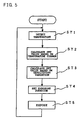
- Fig. 5 shows a flowchart roughly illustrating the processing by the exposure apparatus 20 of this embodiment.
- the exposure apparatus 20 of this embodiment detects a temperature in the vicinity of the LEDs 31 of the exposure head 15 using the temperature sensor 28 as described above.
- the forward voltage across the LEDs 31 and the voltage between the collector and emitter of each transistor switch 32 used in the switching circuit 22, and the like, have several factors that change depending on temperature. Therefore, the exposure apparatus 10 of this embodiment dynamically controls the power to the LEDs 31 by controlling the current or voltage supplied to the LEDs 31 on the basis of temperature so that the brightness of the LEDs 31 is maintained at a constant level when the temperature changes. Further, it is preferable to take into consideration changes in the temperature characteristics of the transistor switches 32 when the value of current or voltage is controlled.
- step ST2 the temperature detected in step ST1 is compared with the temperature at the time of correction stored in the temperature coefficient table of the ROM 27.
- differences relative to the temperature at the time of correction are in correspondence to coefficients to be used to correct the value of current and/or voltage (in this embodiment, the indirect set value Ds for the current or voltage supplied to the power supplying circuit 23) on the basis of the corresponding temperature differences. Therefore, in step ST2, a set value Ds corresponding to the detected temperature is determined from the temperature at the time of correction and a set value using interpolation or the like. Then, the set value Ds for temperature correction that will achieve exposure conditions corresponding to the detected temperature is calculated.
- step ST3 the exposure apparatus 20 of this embodiment corrects the set value Ds for temperature correction on the basis of photosensitive sheet sensitivity variation, image lightness and other conditions, and thereby calculates set values Ds to be supplied to the individual power supplying circuits 23. If there is a setting for user's color tone or the like, the setting is reflected on the set values Ds. In this manner, the exposure apparatus 20 of this embodiment is able to control the set values Ds at any time in steps ST2 and ST3 so that changes in the printing environments of the exposure apparatus 20, such as temperature, photosensitive sheet sensitivity variation, user's taste and the like, are reflected. Because the value of current and/or voltage supplied to the LEDs 31 can be freely controlled using the set values Ds, the conditions of exposure by light-emitting elements, such as LEDs, can be suitably set by dynamically controlling the brightness of the LEDs 31.
- step ST4 exposure duration is set on the basis of the gradation information of pixels to be exposed.
- step ST5 based on the exposure duration, the timing generating circuit 24 outputs to the switching circuit 32 timing signals for causing LEDs 31 to emit light or turning LEDs 31 off. Therefore, each transistor switch 32 of the switching circuit 22 turns on for the exposure duration corresponding to the gradation level to supply the corresponding LED 31 with a predetermined value of power based on the set value Ds set in the steps described above, thereby performing exposure.
- the operation returns to step ST1, where temperature is detected again.
- Such processing can be provided as software that can be executed by the CPU 25. It is possible to store the software in the ROM 27 so that the software is loaded at a suitable timing to control the CPU 25.
- the printing apparatus that performs initial setting of the LEDs using semi-fixed resistors as described above with reference to Figs. 2 and 3, is not able to cope with changes in printing environments, such as temperature, through brightness adjustment.
- the exposure apparatus and the exposure method of this embodiment are able to reflect the interior temperature of the exposure head 15, the sensitivity of each photosensitive sheet, and the like, and thereby calculate set values Ds suitable to the present exposure conditions.
- the set values Ds the value of current or voltage supplied to the LEDs 31 can be dynamically controlled. Since changes in printing environments can be coped with by adjusting brightness, it is possible to print images with stable high quality under various printing environments without needing to adjust the exposure duration by changing the exposure timing in correspondence to temperature changes, the sensitivity of photosensitive sheets, or the like.
- the set values Ds to be supplied to the light source units 29R, 29G, 29B are calculated using, as a reference, the set value at the time of correction stored in the EE-PROM 27.
- the set value Ds0 at the time of correction is determined by performing brightness adjustment of the LEDs 31 during the production process of the printer.
- a set value Ds for each color which is handled as a preset predetermined amount of light (brightness) is determined by measuring the total brightness of the four LEDs 31 of each color using a brightness measuring device, and by feeding the brightness back to the CPU.
- a set value Ds for each color when a predetermined amount of light is obtained is set as a set value Ds0 at the time of correction, and then stored into the temperature coefficient table of the EE-PROM 27 together with the temperature detected at that time. The correction operation is thus completed.
- a second method uses a photosensitive material and is performed in the following procedure.
- correction is performed by the second method, it is preferable to write into the EE-PROM 27 data regarding the sensitivity of the photosensitive sheets used, as well.
- the data of the set value Ds0 at the time of correction written into the EE-PROM 27 may also be a value that contains the temperature at the time of correction, photosensitive sheet sensitivity variation. It is also possible to write thereinto a value standardized for a predetermined temperature or photosensitive sheet sensitivity. Since the exposure apparatus 20 of this embodiment is able to adjust brightness by digital correction controlled by the CPU as described above, it is possible to fully automate the correction operation, thereby eliminating the conventional complicated operations of initially setting many semi-fixed resistors. Furthermore, it is possible to automate the assembly of printers including the correction operation. Therefore, the invention greatly contributes to cost reductions of exposure apparatuses and printers.
- the semi-fixed resistors are not adjusted but data at the time of correction is stored into the rewritable EE-PROM 27. Therefore, the correction can be made after purchase by a user, in addition to the correction performed in a factory. For example, when the printer 10 is connected to a personal computer, the printer 10 can be controlled by a correction program, via the buffer 19. If the aforementioned second method is employed, it is possible to expose photosensitive sheets for correction while comparing the density with the reference density and changing the set values Ds for the individual colors, and to instruct to rewrite data stored in the EE-PROM 27, such as the set value Ds, when a predetermined density is obtained.
- the printer 10 dynamically calculates appropriate set values Ds based on the updated set value Ds and temperature at the time of correction, taking into consideration the interior temperature of the exposure head 15 at the time of exposure, the sensitivity of the photosensitive sheet to be exposed, and user's taste. Therefore, the conditions of exposure by each light source unit 29R-29B can be controlled.
- the power supplying circuit and the switching circuit described above are examples of the small-size and low-price circuits that employ a single transistor switch to enable the constant-current control and the on-off timing control.
- the power supplying circuit having the function of supplying the LEDs with a predetermined current corresponding to the set value outputted from the CPU may be constructed on the basis of other control methods, such as PWM control. Furthermore, it is possible to perform the gradation control on the side of the power supplying circuit.
- the switching circuit may also be constructed using other switching elements, such as MOS. In the invention, it is possible to provide a sufficiently high quality image by using a switching circuit having a resolution that matches the gradation level of images.
- the exposure head in this embodiment employs a light emitting source that has four LEDs for each color, it should be understood that the number of LEDs for a color is not limited to four. It is also possible to use light-emitting elements other than LEDs, for example, semiconductor lasers and the like.
- Fig. 6 illustrates the timing generating circuit 24 in detail.
- the timing generating circuit 24 also has gradation level control portions with the same construction corresponding to the light source units 29R, 29G, 29B. The following description will be made in conjunction with a gradation level control portion 51 that supplies timing signals to the light source unit 29R.
- the gradation level control portion 51 of the timing generating circuit 24 has four 8-bit registers 53a-53d and four 8-bit counters 55a-55d corresponding to the four LEDs 31 (in the description below, referred to as "LED1, LED2, LED3, LED4").
- the four 8-bit registers 53a-53d and the four 8-bit counters 55a-55d form a gradation setting portion, which is supplied with 8-bit data divided from 10-bit data, from the CPU 25 having a function of a main gradation level control portion 52.
- a timing signal is outputted to the LED1-LED4 for controlling exposure duration. Therefore, in this embodiment, the CPU 25 and the timing generating circuit 24 form a gradation control portion 50 that sets a gradation level for gradation expression in the switching circuit 22, which is a time control portion.
- exposure apparatuses such as the exposure apparatus of this embodiment, which employ semiconductor elements (light-emitting elements), such as LEDs, lasers or the like, as light sources
- exposing the identical dot (pixel) by a plurality of light sources is considered in order to secure a certain amount of exposure.
- the exposure head 15 In the serial printer 10 shown in Fig. 1, in which the carriage 13 carrying the exposure head 15 is moved in the scanning directions X and a photosensitive sheet is moved in the sheet conveying direction Y by the sheet conveying roller 11, the exposure head 15 is moved over a front surface of a photosensitive sheet. Therefore, the same or identical dot can be repeatedly exposed to radiation of light (exposure light) from the light-emitting elements suitably arranged in the exposure head 15.
- a plurality of light sources such as LEDs
- the amount of exposure becomes the multiplication product of the light intensity (brightness) of light emitted from the light source and the exposure duration. Therefore, to perform exposure control by changing the amount of exposure of each dot to be exposed, two methods may be considered, that is, changing the light intensity of emitted light, or changing the exposure duration. If light sources, such as LEDs or the like, are used, it is very difficult to dynamically change the light intensity of emitted light for each dot. Therefore, the method wherein the exposure duration is controlled is normally selected for the gradation control as in this embodiment.
- exposure duration control methods may be considered, for example, a binary control method in which exposure is performed, or not performed, during the entire time of an exposure cycle (which is a set interval for irradiation of a dot with light for exposure (exposure light) from a light source.
- an exposure cycle period for a dot elapses, the exposure process for the next dot is started
- a method in which the light emission duration of the light sources, such as LEDs is more finely controlled by duty control within the exposure cycle period, and the like.
- exposure is performed by, for example, using exposure light emitted from four LEDs for one dot
- several methods may be considered, for example, a first method in which exposure is performed on the basis of a combination of only the on/off control of the four LEDs, a second method in which exposure is performed on the basis of the on/off control of three LEDs and the duty control of the remaining one LED, a third method in which exposure is performed on the basis of the duty control of the four LEDs, and the like.
- the first method requires only simple hardware, but is able to express only 5 gradations of 0-4. This is not practical since images formed on photosensitive sheets presently need at least about 256 gradations. Furthermore, the light emitting duration of the four LEDs are not equal but the light emitting duration of some of them becomes very long. Therefore, the deteriorating rate is great, and the characteristics of the LEDs are likely to change. Thus, it is difficult to form stable images, over a long time.
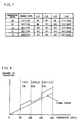
- the second method enables fine gradation control of about 256 gradations simply by fine control, for example, 64-gradation control, of one LED (LED4 in this embodiment) and on/off control of the other three LEDs as shown in Fig. 7. Since this method does not require very complicated hardware, it is possible to provide a low-price exposure head capable of multi-gradation control. However, the individual LEDs have characteristic variations. Therefore, considering the brightness variations of the four LEDs, the amount of exposure deviates from an ideal exposure amount-gradation level curve as shown in Fig. 8 every time a LED to be on/off controlled emits light. That is, continuous and smooth gradation levels cannot be expressed, but there occur regions of stepwise changes.
- LEDs have characteristics that the brightness changes due to heat generation. Since the drive duties of the four LEDs differ from one another in the second method, the extent of heat generated during exposure also varies. Therefore, even if the brightness of the four LEDs in an exposure apparatus are equal in an initial state, the brightness of a LED with a high duty decreases and deviates from the ideal gradation level curve as exposure is repeated. Furthermore, if a certain LED has a duty considerably different from those of other LEDs, the service life of the product may decrease.
- the third method is able to turn on the four LEDs with the same duty. Therefore, multi-gradation control can be performed without the aforementioned stepwise gradation level fluctuations nor the problem of brightness changes during exposure.
- this method requires hardware for multi-gradation control with a resolution of, for example, 256 levels, if an image with 256 gradations for each dot is to be formed by exposure. Since the change in the color development density of actual photosensitive sheets is not linear relative to the change in exposure amount, there is a need to perform gamma-correction wherein exposure amount is adjusted so that the change in color development density becomes linear. Therefore, to realize linear color development density of 256 gradations, the exposure amount control needs to have a resolution higher than 256 gradations.
- the control In the case of exposure of a photosensitive material such as a Cycolor medium, the control needs to have a resolution of about four times as high as the gradation. To form an image with 256 gradations, an exposure control circuit having a resolution of about 1000 (10 bits) is needed. Therefore, the third method requires a control circuit capable of controlling exposure duration with about 1000 gradations for each LED, resulting in a very high hardware cost. Furthermore, to avoid an increase of the printing time, an increase of the exposure cycle period must be avoided. Therefore, for higher gradation levels, hardware with a very fast processing rate becomes needed, which is another factor to increase the costs of exposure apparatuses and printing apparatuses.
- the third method is favorable to form multigradation images, the third method steeply increases the cost of an exposure apparatus having a high resolution of about 1000 gradations, which is normally required for actually-used color printers and the like. It is difficult to employ such an exposure apparatus in printers for personal use or the like which are used together with personal computers at offices or homes.
- the exposure apparatus of this embodiment employs the gradation control portion 50 capable of performing multi-gradation level control and maintaining substantially constant duties of individual light sources, for exposure of dots (pixels) to exposure light emitted from the light sources.
- the gradation control portion 50 can be realized by low-price hardware.
- the gradation control portion 50 of this embodiment is designed to perform multi-gradation level control within a limited exposure cycle period, without requiring a considerably increased processing rate. Further, since correction for changes in the printing environments is performed on the side of the power supplying circuit 23 so that the load on the gradation control portion 50 is reduced, it is possible to realize an exposure apparatus with a fast exposure rate.
- the exposure apparatus 20 of this embodiment is equipped with the light sources LED1-LED4.
- the gradation control portion 50 is provided with the gradation level control portion 50 for supplying gradation data to the LED1-LED4, and the main gradation level control portion 52 for converting gradation information (gradation data) supplied from an image data storing portion 61 in the buffer 19 via a gradation data supplying portion 62, into gradation data of the LED1-LED4 to be turned on, and setting it in the gradation level control portion 51.
- the gradation level control portion 51 is provided with the four 8-bit registers (gradation level setting portions) 53a-53d and the four 8-bit counters 55a-55d corresponding to the LED1-LED4.
- the counters 55a-55d output signals (ripple carriers, RC) 56a-56d which become a high level when a value set in the corresponding counter and down-counting is started, and which become a low level when down-counting is completed so that the counter value becomes 0.
- the signals RC 56a-56d are returned to the enable terminals of the corresponding counters 55a-55d so that when counting is completed, counting is stopped until data is set in the counters 55a-55d at the beginning of the next exposure cycle.
- the signals RC 56a-56c are supplied to the transistors 32a-32d in the switching circuit 22, via buffer drivers 57a-57d. As described above, when the signal RC is at the high level, the corresponding buffer drivers 57a-57d become open-collector, so that the corresponding LED1-LED4 are supplied with power to emit light with a suitable brightness, thereby turning on the LEDs.
- the timing generating circuit 24 is mounted in the exposure head 15, and is supplied with gradation data from the CPU 25 through a flexible cable or the like, the circuit arrangement is not limited to this embodiment. For example, it is also possible to provide the timing generating circuit 24 on a base board separate from the exposure head 15, or to provide the counters 55a-55d and the registers 53a-53d on different base boards.
- the gradation data supplied from the gradation data supplying portion 62 to the main gradation level control portion 52 is 10-bit data, so that about 1000 gradations can be instructed.
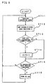
- the main gradation level control portion 52 receives the 10-bit gradation data, and changes it into 8-bit gradation data in the flow illustrated in Fig. 9, and supplies the data to the registers 53a-53d of the gradation level control portion 51.
- the main gradation level control portion 52 obtains from the gradation data supplying portion 62 10-bit gradation data x for the dot which, for example, the LED4 faces in the next exposure cycle.
- step ST12 the data of the higher eight bits of the gradation data x is set in the register (R) 53d corresponding to the LED4.
- step ST13 the data of the lower two bits of the gradation data x is checked. If the data of the lower two bits is a predetermined value corresponding to the LED4, 1 is added to the value of the register (R) 53d in step ST14.
- This embodiment converts 10-bit gradation data into 8-bit gradation data by cyclically increasing the gradation levels of the four LED1-LED4 in the above-described manner. Therefore, if the lower two bits of the gradation data x are "00", step St14 is not performed for any of the registers 53a-53d corresponding to the LED1-LED4, so that the LED1-LED4 emit light for the same exposure duration. If the lower two bits of the gradation data x are "01", the value of the register, for example, 53d corresponding to the LED4, is incremented by 1, so that only the LED4 emits light for a one-level longer duration than the other LEDs. That is, the total exposure duration by the LED1-LED4 is increased by an amount of one level.
- the values of the registers 53c, 53d corresponding to the LED3 and LED4 are incremented by 1, so that the LED3 and the LED4 emit light for a one-level longer duration. That is, the total exposure duration is increased by an amount of two levels. If the lower two bits of the gradation data x are "11”, the values of the three registers 53b-53d corresponding to the LED2-LED4 are incremented by 1, so that the total exposure duration is increased by an amount of three levels.
- step ST15 the above-described steps are repeated until 8-bit gradation data is set into all the registers 53a-53d corresponding to the LED1-LED4.
- 8-bit gradation data is set in the registers 23a-23d
- the values of the registers 53a-53d are loaded into the counters 55a-55d in step ST16 when the start signal 59 of the next exposure cycle enters a control portion 63 of the CPU 25.
- the LED1-LED3 emit light until the values of the counters 55a-55d are counted down to zero as described above.
- the 10-bit gradation data x is converted into 8-bit gradation data, and the LED1-LED4 are turned on at the respective duties instructed by the 8-bit gradation data.
- the exposure apparatus 20 of this embodiment is not designed such that exposure light from the LED1-LED4 simultaneously strikes each dot.
- the exposure head 15 is moved in the scanning directions x and the medium 1 is conveyed so that each dot receives exposure light from the LED1-LED4 at intervals of exposure cycle periods. That is, the total exposure duration for each dot is obtained as a sum of the light-emitting durations of the individual LED1-LED4. Therefore, although the LED1-LED4 are controlled on an 8-bit basis, 10-bit resolution is obtained in terms of the total exposure duration.
- Fig. 10 shows examples of the 8-bit gradation levels allotted to the LED1-LED4 for the 10-bit gradation data x indicating gradation level.
- the exposure apparatus 20 of this embodiment performs exposure to a color using four LED1-LED4. Therefore, if the 10-bit gradation data x increases or decreases by 4 level, the gradation data of each of the LED1-LED4 is cyclically increased or decreased by one level. Thereby, 10-bit resolution can be achieved as a result of the total exposure by the LED1-LED4. Furthermore, if a dot is exposed to light from the LED1-LED4, the LED1-LED4 emit light in substantially the same conditions (duties), with the exposure duration by the LED1-LED4 varying by at most one level.
- each dot with amount of exposure that linearly corresponds to the 10-bit gradation levels in overall view although, in a microscopic view, the brightness variation of the LED1-LED4 appears as indicated in Fig. 11. Since the control of the light sources LED1-LED4 is performed based on 8-bit gradation control, it is possible to employ 8-bit registers and counters. Furthermore, since the data transferred from the CPU 25 to the registers is also 8-bit data, the processing rate can be improved, and the need to considerably increase the hardware speed is eliminated.
- the exposure apparatus 20 of this embodiment if the value of 10-bit gradation data x exceeds 1020 (1111111100 in binary), the 8-bit gradation data to be supplied to the LED1-LED4 is overflown. Therefore, if gradation data exceeding 1020 is supplied to the main gradation level control portion 35, a limiter is provided so that the maximum gradation data in 8 bits can be supplied to the LED1-LED4. With this construction, the exposure apparatus 20 of this embodiment prevents occurrence of failures or defects during print processing, and prevents uneven color development in a printed image, and therefore prevents deterioration of image quality, even if there is data exceeding 1020.
- this embodiment uses four light sources (LEDs) to express gradation levels instructed in 10 bits, the data of the higher 8 bits of the 10 bits corresponding to the result of division of the 10-bit data by 4 is unconditionally set in the register of each light source while the data of the lower 2 bits corresponding to the remainder of division of 10-bit data by 4 is used to increase the gradation level of the corresponding light source by 1 for fine adjustment.
- LEDs light sources
- the invention is not limited by the construction having four light sources or four groups of light sources.
- the invention can be applied in an exposure apparatus that performs exposure using m number of light sources or m number of groups of light sources in accordance with the amount of light or kind of individual light sources.
- n integer
- n/m integer of n/m. Therefore, it becomes necessary to provide in the gradation level control portion a gradation level setting portion, such as a register, which is capable of setting gradation data of at least l number of gradation levels.
- the gradation data for a given dot is at gradation level i, an integer value j and a remainder k are obtained through division of the gradation level i by m.
- the gradation level is set to j + 1.
- the gradation level is set to j. If each dot is exposed on the basis of control of m number of light sources at l number of gradation levels which is less than n number, the total amount of exposure has a resolution of n number of gradation levels as stated above.
- the circuits for controlling the individual light sources can be simplified, thereby providing a low-price exposure apparatus having a high processing rate and a high resolution. Furthermore, since a dot is exposed to light emitted from individual light sources at substantially equal duties, the individual variation of the light sources will not evidently show, but a substantially linear characteristic is obtained. Further, since the individual light sources emit light at equal gradation levels (exposure duration, or duty), it is possible to prevent inconvenient incidents where a particular light sources quickly deteriorates or changes in characteristics due to temperature.
- the exposure apparatus and the exposure method of this embodiment make it possible to realize an exposure apparatus having substantially linear characteristics as mentioned above while employing, as light sources, LEDs, which are inexpensive and stable light sources but have disadvantages in that the range of individual variation is normally unignorable and in that a single LED element is not sufficient to provide a required amount of light for exposure of a photosensitive medium. Therefore, it becomes possible to provide a low-price and small-size printing apparatus, such as a color printer, that is suitable for personal use and capable of printing high-quality images.
- the exposure method of this embodiment can be applied to an exposure apparatus that simultaneously turns on a plurality of light sources, such as LEDs, and converges the light therefrom onto a single dot using a lens system or the like.
- the exposure method of this embodiment is also applicable to an exposure apparatus that has an array of many light sources, such as LEDs, arranged in the scanning directions and simultaneously exposes a row or rows of dots in the scanning direction.
- the registers are used to distribute a multi-gradation level cyclically to the LEDs
- similar processing may be performed by software using the CPU.
- a program having instructions to perform the processing equivalent to the steps illustrated in Fig. 9 is pre-stored in the ROM 27, and loaded into the CPU 25 at a suitable timing to perform the processing.
- the exposure apparatus and the exposure method of this embodiment described above are applicable to not only a type of printing apparatus wherein the exposure head is moved as shown in Fig. 1, but also any printing apparatus employing light-emitting elements, such as LEDs, for example, a printing apparatus wherein the light-emitting elements are arranged in an array extending in the direction of width of a print sheet.
- any printing apparatus employing light-emitting elements such as LEDs
- the light-emitting elements are arranged in an array extending in the direction of width of a print sheet.
- the invention comprises a power supplying circuit having a power control function capable of adjusting brightness of a light-emitting element, such as an LED, by dynamically controlling the power supplied to the light-emitting element, and a timing generating circuit having a time control function capable of dynamically controlling exposure duration.
- a power control function capable of adjusting brightness of a light-emitting element, such as an LED
- a timing generating circuit having a time control function capable of dynamically controlling exposure duration.
- the exposure apparatus of the invention is able to perform digital control of brightness adjustment using a CPU, so that complicated adjustment operation using semi-fixed resistors can be eliminated. Therefore, it is possible to fully automate the production, including correction of exposure apparatuses on the production line, and therefore considerably reducing the production cost.
- the exposure apparatus of the invention sequentially changes the gradation level of each light source and controls each light source at gradation levels that are fewer than the gradation levels for each dot. Therefore, the exposure apparatus is able to perform processing at a fast rate and forms a multi-gradation image using relatively simple hardware. Further, since a plurality of light sources are turned on at substantially equal gradation levels at any gradation level, the individual variation of the light sources hardly appears but the amount of exposure obtained becomes substantially linear to the gradation levels. Further, it is possible to prevent incidents where a particular light source deteriorates relatively quickly or changes in characteristics to affect the gradation levels.
- the invention is able to dynamically perform adjustment of brightness using a control mechanism separate from that for gradation control and realize high gradation level control using simple hardware, it becomes possible to provide a low-price exposure apparatus and a low-price printing apparatus capable of processing a multi-gradation image with a high resolution at a fast rate. Furthermore, it is possible to realize a color printing apparatus which uses inexpensive light sources, such as LEDs, but is capable of forming, at a fast rate, a high-quality image with good color balance and reduced color distortion, and which is easy to use together with personal computers or the like at offices or homes.
- the invention is an exposure apparatus and an exposure method which are suitable to a compact-size printer capable of full-color printing with multi-gradation using a photosensitive sheet, such as a Cycolor medium.
- the invention makes it possible to provide a low-price printer suitable for personal use and capable of high-quality printing using a photosensitive medium.
Abstract
In an exposure apparatus for exposing a photosensitive
medium, such as a Cycolor medium, using light-emitting elements,
such as LEDs, correction of environmental conditions at the time
of exposure that change depending on temperature and the like is
performed by dynamically changing the value of current or voltage
to be supplied to the LEDs. Thereby, control of exposure duration
can be performed solely for expression of multi-gradation levels,
so that a very high resolution is not required for the control
of exposure duration. Therefore, it is possible to realize a
low-price exposure apparatus capable of printing multi-gradation
images. For exposure to a single color using a plurality of LEDs,
the gradation level to be expressed by the individual LEDs is
cyclically changed, so that the construction of gradation level
control for each LED can be simplified. Further, since the LEDs
can be used at substantially equal duties, the individual
variation of LEDs does not evidently show. It is also possible
to prevent an inconvenient incident where a particular LED
deteriorates.
Description
The present invention relates to an exposure apparatus, an
exposure method and a printing apparatus that are capable of
forming an image on a photosensitive sheet such as a Cycolor
medium.
As a method for forming a color photograph or a color print,
there is a method for forming an image, such as a picture or a
character, on a photosensitive sheet by exposing the sheet. There
are different types of photosensitive sheets, for example, a
photosensitive sheet employing a multi-layer color development
method, in which sheet three or more layers of photosensitive
emulsions with different color sensitivities are layered on a
single supportive sheet thus forming a photosensitive member, a
photosensitive sheet that employs a film in which each emulsion
layer contains a pigment and a developing agent so that the film
is capable of being exposed and developed simultaneously, and the
like. A still another photosensitive sheet is a so-called Cycolor
medium, which employs, as a photosensitive material,
microcapsules (cyliths) that contain a chromogenic substance and
a photoinitiator. In the Cycolor medium, a thin supportive body
formed from, for example, polyester, is coated with numerous
cyliths of a very small size. When exposed to light, cyliths
harden so that only the cyliths of a specific color are activated,
and the cyliths are ruptured by pressurization, thereby forming
a predetermined image of a specific color. Other photosensitive
sheets have different color development principles, but are
exposed to light of the color of an image or its complementary
color to form an image.
In widely used methods for exposing a photosensitive sheet
as described above, white light is split into three primary colors
by a filter or the like, and images are formed using the individual
primary colors, and then combined to form an image of
predetermined colors or an image of their complementary colors
on the photosensitive media. Another technology has recently
been developed, as disclosed in Japanese patent application
laid-open Nos. Hei 5-211666 and Hei 5-278260, in which LEDs or
lasers that emit red, green and blue light are employed as
light-emitting sources, and the light-emitting sources are
controlled so that an cage of predetermined colors is formed on
a photosensitive sheet and the sheet is thereby exposed.
Employment of LEDs or the like as light sources (light-emitting
elements) for individual colors allows a compact
construction of the light sources. Furthermore, provision of the
light sources for individual colors enables control of exposure
duration, brightness and the like. For a photosensitive sheet
employing photosensitive materials having different exposure
characteristics for individual colors, a design has been
considered in which the exposure duration and brightness can be
set appropriately for each color, whereby it will become possible
to form images with good color balance and reduced color
distortion on a medium in which the photosensitive materials have
different exposure characteristics to different colors.
A printing apparatus 10, as shown in Fig. 1, equipped with
an exposure apparatus having LEDs or lasers as light-emitting
elements, has been developed. In the printing apparatus 10, an
exposure head 15 is mounted on a carriage 13, and the carriage
13 is moved along a shaft 12 in scanning directions X. A
photosensitive sheet 1, such as a Cycolor medium, is conveyed by
a sheet-conveying roller 11 in a predetermined direction
(sheet-conveying direction) Y. The photosensitive sheet 1 is
thereby moved relative to the light-emitting elements of the
exposure head 15, so that the entire photosensitive sheet is
exposed to light from the LEDs or lasers of the exposure head 15
to form an image.
Fig. 2 shows an example of the arrangement of the exposure
head 15, especially relating to the exposure head 15 having LEDs
31 for red color (R). In the exposure head 15, exposure is
performed by light-emitting sources 21 each having four LEDs 31
for a single color. Each LED 31 of the light-emitting source 21
emits light when power is supplied thereto from a power supplying
circuit 23. The light emitting duration (exposure duration) of
each LED 31 is controllable by a switching circuit 22. The power
supplying circuit 23 has a constant voltage power source 34, and
semi-fixed resistors 33 for setting the power supplied to the
corresponding LEDs 31 in accordance with the brightness of the
corresponding LEDs 31. During assembly in a factory or
immediately before shipment, the semi-fixed resistors 33 are
adjusted so that the brightness of the red (R), green (G) and blue
(B) light emitting sources become predetermined values at the time
of shipment. Normally, the individual variation of LEDs is large
and the variation in amount of light emission (brightness) is
large, and many photosensitive sheets have different
sensitivities depending on wavelengths. Therefore, the semi-fixed
resistors 33 are provided in the power supplying circuit
23 to set power supplied to each LED in accordance with the
variations of LEDs and basic characteristics of photosensitive
sheets depending on wavelengths.
In the switching circuit 22, a transistor switch 32 is
provided for each LED 31. A CPU 25 controls a timing generating
circuit 24 on the basis of pixel gradation information. Each
transistor switch 32 is turned on and off by a signal from the
timing generating circuit 24. Therefore, the duration of power
supply to each LED 31 is controlled by the signal from the timing
generating circuit 24, so that the duration of exposure of a
photosensitive sheet can be controlled separately for each color
and each LED 31.
As described above, while it has a simple circuit
arrangement, the exposure head 15 shown in Fig. 2 is able to absorb
or offset the individual variations of the LEDs by using the
semi-fixed resistors. Therefore, it is possible to provide
initial settings in accordance with the basic characteristics of
a photosensitive sheet to be exposed. However, since the forward
voltage of the LEDs 31 and the voltage between the collector and
emitter of each transistor switch 32 changes depending on
temperature, the value of drive current supplied to the LEDs 31
changes with changes in ambient temperature or operating
conditions of the exposure head 15. As a result, the color tone
of an image formed by exposure may vary or uneven color development
may occur, depending on the operating conditions.
Fig. 3 shows another example of the exposure head 15 having
LEDs. In this exposure head 15, constant current circuits 35 are
provided in a power supplying circuit 23 corresponding to LEDs
31 provided in a light emitting source 21, so that the initial
setting of the current to be supplied to the LEDs 31 from the
constant current circuits 35 can be made using the semi-fixed
resistors 33. Therefore, a constant current is supplied to each
LED 31 despite changes in temperature depending on operating
conditions, so that images with relatively stable color tones can
be obtained.
However, in the exposure head 15, the semi-fixed resistors,
provided in the same number as that of the LEDs, are adjusted at
a timing when the initial setting of the semi-fixed resistors is
possible, such as at the time of shipment. Once adjusted, the
semi-fixed resistors cannot be re-adjusted. Therefore, for
changes of the environmental conditions (printing environments)
which occur despite maintenance of constant current values, for
example, fluctuation of brightness of LEDs depending on
temperature, sensitivity variations of a photosensitive sheet,
temperature-dependent sensitivity changes of the photosensitive
sheet, lightness changes or color tone changes made in accordance
with user's taste, and the like, this exposure head 15 also
requires that the duration of exposure by the LEDs be changed by
controlling the switching circuit 22 during operation of the
printing apparatus to achieve corrections for changes in
brightness of LEDs and the like.
The duration of exposure by LEDs is controlled by the
switching circuit 22, the CPU 25 and the timing generating circuit
24, and can be used as a basis for corrections for changes in
printing environments and gradation control if the gradation
level is as low as about several tens of gradation increments.
However, since graduation control at a level of about 256-1024
gradation increments is recently required, a control mechanism
with a resolution higher than the graduation level is needed in
order to perform gradation control and corrections for changes
in brightness and the like on the basis of exposure duration.
Therefore, the control mechanism, the exposure head and the
printing apparatus become very expensive. As the gradation level
increases, such cost increases become greater. To solve this
problem, it is possible to use LEDs that have reduced individual
variations and stable temperature characteristics and therefore
requires brightness adjustment to a less extent, or to use
photosensitive sheets in which the characteristic variation among
lots is small. This may curb the cost increase of the exposure
duration control mechanism, but results in cost increases of LEDs
and photosensitive sheets.
If corrections for environmental changes are performed on
the basis of exposure duration, the exposure duration per exposure
cycle of a single dot becomes short when, for example, the LED
brightness is increased. Therefore, if the gradation level
becomes high, it becomes impossible to secure a sufficient
resolution in the direction of the time axis for graduation
control, so that sufficient graduation expression cannot be
obtained. Then, various problems arise. That is, if the
correction is simplified in order to obtain sufficient gradation
expression, the image resolution decreases depending on
temperature or the sensitivity of photosensitive sheets.
Conversely, if the gradation level control is simplified, desired
color expression may not be obtained. It is possible to increase
the exposure duration in order to secure a certain resolution.
However, an increase in exposure duration per dot will
considerably increase the time required for printing.
Accordingly, it is an object of the invention to provide
an exposure apparatus, an exposure method and a printing apparatus
that always allow easy correction for changes in environmental
conditions that include temperature regarding light-emitting
elements, such as LEDs, sensitivity of photosensitive sheets, and,
in addition to correction for changes in environmental conditions,
provide sufficient gradation expression. It is an another object
of the invention to make it possible to provide an exposure
apparatus and a printing apparatus that have a function for
correction regarding environmental conditions and a function
capable of gradation expression at a high gradation level. It
is still an another object of the invention to provide an exposure
apparatus and a printing apparatus that perform printing with high
image quality without requiring expensive LEDs or a
photosensitive sheet which have stable characteristics.
It is a further object of the invention to provide an
exposure apparatus and an exposure method that allow easy initial
setting of light-emitting elements using a simple circuit
arrangement and that allow a user to easily correct or adjust the
conditions of exposure by light-emitting elements even after
shipment from a factory.
According to the invention, a power control portion capable
of dynamically changing the power supplied to light-emitting
elements by controlling the current or voltage supplied to the
light-emitting elements, and a time control portion capable of
dynamically changing and controlling the exposure duration are
provided. Therefore, one of the power control portion and the
time control portion performs gradation display, and the other
corrects exposure conditions for environmental changes. For
example, the time control portion is used for the gradation
expression, and the power control portion is used for the
correction, so that corrections regarding variations in
temperature or the sensitivity of photosensitive sheets can be
performed without reducing the resolution needed for the
gradation expression.
The exposure apparatus of the invention is characterized
by comprising: a light-emitting element that emits light for
exposure of a photosensitive sheet; a power control portion
capable of controlling current or voltage or both to be supplied
to the light-emitting element; and a time control portion capable
of controlling duration of exposure by the light-emitting element,
one of the power control portion and the time control portion
performing gradation expression of an image formed on the
photosensitive sheet, and the other one performing correction of
an exposure condition in accordance with an environmental change
at the time of exposure.
Compared with the power control portion for controlling
power supplied to the light-emitting element by changing current
or voltage, the time control portion allows easy employment of
switching control, so that a high resolution can be obtained.
Therefore, it is preferable to use the time control portion to
perform the gradation display and use the power control portion
to perform the correction in accordance with changes in printing
environments. If the correction in accordance with environmental
changes is performed separately from the gradation display, the
control portion for the gradation display, for example, the time
control portion, has a reduced control load. Therefore, it is
possible to employ simple circuits whose resolution is not so very
high, in the time control portion, which circuits can be obtained
at low costs.
In the exposure apparatus of the invention, since the value
of current or voltage supplied to the light-emitting elements,
such as LEDs, semiconductor lasers or the like, can be controlled,
that is, dynamically changed, at the time of an exposure operation,
the brightness itself of the light-emitting element can be
dynamically adjusted. Therefore, the power control portion is
able to maintain constant brightness of the light-emitting
elements by correcting for changes in characteristics of the
light-emitting elements depending on temperature changes. It is
also possible to change the brightness of the light-emitting
elements to cope with lot variations of photosensitive sheets or
changes in photosensitive sheet sensitivity due to temperature
changes. Furthermore, it is possible to cope with a lightness
change or a color tone change according to user's taste by the
power control portion controlling the brightness of the
light-emitting elements. Since all the exposure conditions that
require correction depending on changes in printing environments
can be adjusted by dynamically changing the brightness of the
light-emitting elements in the manner described above, the time
control portion only needs to control the exposure duration on
the basis of gradation information. Therefore, the resolution
of the side of gradation control is free from the burden of
correction regarding environmental conditions, but time can be
fully utilized on the gradation control side so that a high
resolution for gradation expression can be reliably provided.
Further, it becomes unnecessary to provide the time control
portion with a resolution that is higher than the resolution
required in order to reproduce image data. Therefore, the
exposure apparatus of the invention is able to print high-quality
multi-gradation images using a small-size simple time control
portion. Therefore, using the exposure apparatus of the
invention, it becomes possible to provide a low-price, small-size
printing apparatus capable of printing an image expressed
with multi-gradations.
If the power control portion is used to perform correction
based on the temperature in the vicinity of the light-emitting
elements, the exposure apparatus of the invention further
comprises: a set value control portion capable of changing a
value of current or voltage to be supplied from the power control
portion to the light-emitting element; a temperature sensor that
detects a temperature in the vicinity of the light-emitting
element; and a memory capable of storing data regarding and the
direct or indirect value of current or voltage supplied to the
light-emitting element when brightness of the light-emitting
element is corrected and a temperature at that time, wherein the
set value control portion controls the value of current or voltage
to be supplied to the light-emitting element, on the basis of data
in the memory and the temperature detected by the temperature
sensor. An input portion capable of inputting information
regarding sensitivity of the photosensitive sheet may also be
provided, so that a set value control portion corrects the value
of current or voltage to be supplied to the light-emitting element
on the basis of the information regarding sensitivity of the
photosensitive sheet. Therefore, it becomes possible to correct
exposure conditions for variation in photosensitive sheet
sensitivity. Since the value of current or voltage and the
temperature at the time of the correction are stored in the memory,
the initial setting of exposure conditions can be easily performed.
Furthermore, it also becomes possible to correct the exposure
conditions by updating the data in the memory during use.
The exposure apparatus described above is able to perform
correction of exposure conditions and gradation control using an
exposure method comprising the following steps:
In the second step, it is also possible to correct the
current or voltage to be supplied to the light-emitting element
in accordance with the information regarding the sensitivity of
a photosensitive sheet or user's taste of lightness or color tone.
This exposure method may be provided as a logic circuit in
the form of hardware, or may be provided in the form of software
for controlling a microcomputer or the like, which is installed
in a memory medium, such as a ROM, that can be readable by a
computer.
As described above, the exposure apparatus of the invention
is able to dynamically perform correction of exposure conditions
based on changes in environments, such as temperature,
photosensitive sheet sensitivity variation and the like, and is
able to secure a resolution required for gradation control without
using an expensive control mechanism. Therefore, using a
printing apparatus comprising the exposure apparatus of the
invention and a conveying apparatus that conveys at least one of
a photosensitive sheet and the exposure apparatus at a
predetermined timing relative to each other, it is possible to
provide a low-price, small-size printing apparatus capable of
printing color images with stable high quality without being
affected by variations in temperature or photosensitive sheet
sensitivity.
If a plurality of groups of light-emitting elements are
assigned to a color and a plurality of groups of light-emitting
elements are used to display or express gradations, it is
preferable to control light emission of the light-emitting
elements at substantially equal duties. However, if each group
of light-emitting elements are controlled with a high resolution
of, for example, 1000 gradations, the hardware cost becomes very
high. In this invention, the gradation level of the individual
light-emitting elements (light sources), such as LEDs, of the
plurality of groups is cyclically changed in accordance with the
total gradation level of exposure of each dot. In this manner,
the gradation level required for control of each groups of
light-emitting elements can be reduced, and the light-emitting
elements of all the groups can be turned on at substantially equal
duties.
That is, an exposure apparatus according to the invention
is characterized by further comprising: a plurality m of groups
of the light-emitting elements (light sources), and a gradation
control portion capable of setting a gradation level for gradation
expression using one of the power control portion and the time
control portion, the gradation control portion having a main
gradation level control potion to which gradation information
capable of instructing a gradation level whose maximum is an
integer n is inputted, and m number of gradation level setting
portions into which l number of gradation levels, wherein l is
an integer equal to or greater than an integer obtained by dividing
the integer n by the integer m, can be set with respect to each
group of the light-emitting elements, wherein the main gradation
level control portion sets a gradation level j + 1 which is higher
by 1 than a gradation level j, into gradation level setting
portions pre-set within a kth position, and sets the gradation
level j into the other gradation level setting portions, wherein
j is an integer obtained by division of a gradation level i of
the gradation information by the integer m, and k is a remainder
obtained by the same division.
For example, in an exposure apparatus comprising four
groups of light-emitting elements, each group having a single
light-emitting element, that is, in an exposure apparatus
comprising four light-emitting elements, a resolution of about
1000 gradation levels may be achieved by providing a main
gradation level control portion to which 10-bit gradation
information capable of instructing about 1000 gradation levels
is inputted, and four 8-bit gradation level setting portions into
which 256 gradation levels can be set with respect to each of the
four light-emitting elements. In this arrangement, the main
gradation level control portion sets the higher 8 bits of
gradation information, that is, an integer obtained by dividing
the 10-bit gradation information by 4, into the gradation level
setting portions, and 1 is added to the value of the gradation
level setting portions corresponding to the lower 2 bits of the
gradation information, that is, the value of a remainder obtained
through the division of the 10-bit gradation information by 4.
Then the light-emitting elements are turned on in accordance with
the values of the corresponding gradation level setting portions.
If gradation levels are set in the time control portion
using the gradation control portion, it is possible to duty-control
the individual light-emitting elements on the basis of
the values of the corresponding gradation level setting portions.
Further, if the duration of exposure by the individual groups of
light-emitting elements is cyclically changed at 8-bit gradation
levels, the duration of exposure by all the light sources has a
resolution corresponding to 10-bit gradation information.
In an exposure method according to the invention wherein
gradation expression is performed, the light-emitting elements
pre-set within the kth position among m number of groups of
light-emitting elements are caused to emit light at a gradation
level j + 1 which is higher by 1 than a gradation level j, and
the other light-emitting elements are caused to emit light at the
gradation level j, wherein j is an integer obtained by division
of a gradation level i, instructed for a certain dot, by the integer
m, and k is a remainder obtained by that division. Therefore,
an exposure method for forming an image by scanning individual
dots with light emitted from four groups of light-emitting
elements for each color, is characterized in that when exposure
duration is set in the above-described third step and the
light-emitting elements are turned on in the fourth step, the
following steps are repeatedly performed:
The exposure method comprising the above-described steps
may be provided as a logic circuit in the form of hardware, and
may also be provided in the form of software for controlling a
microcomputer, which software is installed in a ROM or the like.
By cyclically controlling the gradation levels of the
plurality of groups of light-emitting elements in the manner
describe above, it become possible to achieve gradation levels
indicated by, for example, 10-bit gradation information, based
on 8-bit gradation levels for each light source. Therefore, the
hardware for controlling the light sources can be simplified, and
multi-gradation expression can be achieved without requiring a
very high resolution of the hardware. Consequently, it becomes
possible to print an image with multi-gradation levels using
low-cost hardware. Furthermore, since the light-emitting
elements are turned on at substantially equal gradation levels
with the difference being at most 1 level, their duties also become
substantially equal. Therefore, the problem of brightness
changes during exposure is eliminated, and the problem of
deterioration of a particular light source is also prevented.
Fig. 1 is a diagram schematically illustrating a
construction of a printing apparatus that exposes a
photosensitive using LEDs as light-emitting elements.
Fig. 2 is a diagram illustrating an example of the exposure
apparatus having a function of adjusting variations in LED
brightness.
Fig. 3 is a diagram illustrating another example of the
exposure apparatus having a function of adjusting variations in
LED brightness.
Fig. 4 is a block diagram schematically illustrating a
construction of a printer according to the invention.
Fig. 5 is a flowchart illustrating an exposure method
wherein the power control of the printer shown in Fig. 4 is
performed.
Fig. 6 is a block diagram schematically illustrating a
timing generating circuit of a printer according to the invention.
Fig. 7 shows control states of four LEDs at the time of
exposure performed by gradation control of one of the LEDs.
Fig. 8 is a graph indicating the characteristics of amount
of exposure where the control method indicated in Fig. 7 is
employed.
Fig. 9 is a flowchart illustrating an exposure method
wherein the timing generating circuit shown in Fig. 6 is employed.
Fig. 10 shows control states of LEDs based on the exposure
method illustrated in Fig. 9.
Fig. 11 is a graph indicating the characteristics of amount
of exposure by the control method illustrated in Fig. 9.
Embodiments of the invention will be described hereinafter
with reference to the drawings. Fig. 4 shows a block diagram of
a printing apparatus 10 according to the invention. The general
construction of the printing apparatus (printer) 10 is
substantially the same as that shown in Fig. 1. An exposure head
15 is mounted on a carriage 13 which is moved relative to a
photosensitive medium 1 in scanning directions X. The medium 1
is conveyed in a sheet conveying direction Y perpendicular to the
scanning directions X. Therefore, the exposure head 15 is
operated over the entire medium 1 to form an image.
As shown in Fig. 4, the printer 10 of this embodiment is
designed to be generally controlled by a CPU 25, that is, a central
processing unit. Under control of the CPU 25, the exposure head
15 and the photosensitive print sheet (medium) 1 are moved in
accordance with the exposure cycle of exposure of individual dots
on the medium 1. To perform such control, the CPU 25 has a function
of controlling a sheet conveying roller 11 through a sheet
conveyance control portion 17, and a function of controlling a
carriage motor 14 for reciprocating the carriage 13 along a shaft
12 in the scanning directions X through a carriage control portion
18. The CPU 25 further has a function of receiving image data,
including gradation data, from a host apparatus, such as a
personal computer, via a buffer 19, and exposing the medium 1 by
controlling the exposure head 15 on the basis of the image data
received.
An exposure apparatus 20 of this embodiment employs LEDs
31 as light-emitting elements. The exposure apparatus 20 has
light source units 29R, 29G, 29B that are provided with a plurality
(four in this embodiment) of LEDs 31 of three primary colors (red
(R), green (G) and blue (B) in this embodiment, but cyan, magenta
and yellow are also possible), respectively. Since the light
source units 29R, 29G and 29B have the same construction, the red
light source 29R will be described below as a representative. The
light source unit 29R has a light-emitting source 21 having four
LEDs 31 as light-emitting elements, a power supplying circuit 23
having a function of controlling the current supplied to the LEDs
31, and a switching circuit 22 having a time control function of
controlling exposure duration by controlling the duration of
energization of the LEDs 31. The switching circuit 22 has four
transistor switches 32 for turning on and off the corresponding
LEDs 31. In this embodiment, the collector side of each npn-type
transistor switch 32 is connected to the corresponding LED
31, and the emitter side thereof is grounded via an emitter
resistor 36. The base side of each transistor switch 32 receives
a timing signal for controlling the on/off timing from a timing
generating circuit 24. When the timing signal is ON, open
collector condition is established. When the timing signal is
OFF, ground connection is established to provide a low electric
potential.
The power supplying circuit 23, which controls the power
supplied to the LEDs 31, has a D/A converter 39 for converting
a set value Ds supplied from the CPU 25 in the form of a digital
signal, into an analog signal, and an operational amplifier 38
for maintaining an electric potential on the base side of each
transistor switch 32 at a set voltage Vs supplied from the D/A
converter 39, and pull-up resistors 37 for limiting the current
at the time of control of the transistor switch 32. In the light
source unit 29R of this embodiment, when the timing signal from
the timing generating circuit 24 becomes open collector, the
base-side electric potential of the transistor switch 32 is raised
by the set voltage Vs supplied from the D/A converter 39, so that
the transistor switch 32 turns on. The LED 31 thereby emits light.
The current through the transistor switch 32, that is, the current
supplied to the corresponding LED 31, increases until the electric
potential caused by a voltage drop of the emitter resistor 36
reaches the set voltage Vs. When the set voltage Vs is reached,
that current value is maintained. When the timing signal becomes
the grounded electric potential, the base-side electric potential
of the transistor switch 32 decreases, so that the transistor
switch 32 turns off. The power supply to the LED 31 is thereby
discontinued, so that the LED 31 goes out. By controlling the
timing signal in this manner, the on/off timing of the LEDs 31
is controlled. Thereby, the exposure duration during which the
medium 1 is exposed to light emitted from the LEDs 31 is controlled.
In the light source unit 29R of this embodiment, the
lighting duration of each LED 31, that is, the exposure duration,
is controlled by the timing signal supplied from the timing
generating circuit 24. The same control is performed in the other
light source units 29G and 29B. In the light source units 29R,
29G, 29B of this embodiment, a constant value Is of current
determined by the set voltage Vs flows to the LEDs 31 during the
lighting thereof. The current value Is can be freely controlled
by varying the set voltage Vs. Since the set voltage Vs is set
by the digital value Ds supplied from the CPU 25, the exposure
apparatus 20 of this embodiment always allows free dynamical
control of the value of current supplied to the LEDs 31 through
the CPU 25. Furthermore, as shown in the drawings, the exposure
apparatus 20 of this embodiment supplies digital set values Ds
from the CPU 25 to the light source units 29R, 29G, 29B, separately,
so that the current supplied to each light source unit 29R, 29G,
29B can be dynamically controlled.
The timing generating circuit 24, which controls the LEDs
31 of each light source unit 29R, 29G, 29B, receives a signal
regarding colors and gradations, from the CPU 25 based on the image
data inputted into the buffer 19. The construction of the timing
generating circuit 24 will be described in detail later. The
timing generating circuit 24 outputs timing signals at exposure
duration timings suitable to the colors and gradation displays
indicated by the image data supplied thereto. The timing signals
are supplied to the transistor switches 32 of the switching
circuit 22 of each light source unit 29R, 29G, 29B. In the
exposure apparatus 20 of this embodiment, the light source units
29R, 29G, 29B and the timing generating circuit 24 are mounted
in the exposure head 15. The light source units 29R, 29G, 29B
and the timing generating circuit 24 are supplied, from the CPU
25, with signals regarding colors and gradations, and the set
value Ds for controlling the value of current supplied to each
light source unit 29R, through a flexible cable or the like.
The exposure apparatus 20 of this embodiment further has
a temperature sensor 28 for detecting a temperature in the
exposure head 15, and an EE-PROM 27, that is, a memory, capable
of storing data for corrections, a temperature coefficient table
for temperature corrections, programs for the CPU 25, and other
set values and the like. These are accessible by the CPU 25
anytime. Stored in the temperature coefficient table of the
EE-PROM (hereinafter, referred to as "ROM") 27 are a temperature
at the time of correction of the brightness of the LEDs 31 of the
light source, the set values Ds corresponding to the values of
current supplied to the light source units 29R, 29G, 29B at the
time of correction of the LED brightness. Therefore, the CPU 25
compares the temperature detected by the temperature sensor 28
with the temperature at the time of correction, and corrects the
set value Ds at the time of correction in accordance with the values
in the temperature coefficient table to calculate set values Ds
suitable to the interior temperature of the exposure head 15. The
set values Ds are then supplied to the light source units 29R,
29G, 29B.
The exposure apparatus 20 of this embodiment is capable of
receiving from the host apparatus via the buffer 19, data
regarding photosensitive sheet sensitivity variation, and data
regarding image lightness (brightness and/or clearness) in
accordance with user's taste, and updating the data in the ROM
27 with the received data, and holding the updated data.
Therefore, the set values Ds calculated on the basis of the
interior temperature of the exposure head 15 can be further
adjusted with the conditions in printing environments, such as
photosensitive sheet sensitivity variation, image lightness and
the like, to calculate final values Ds using those factors. The
final set values Ds are supplied to the light source units 29R,
29G. 29B. The data regarding photosensitive sheet sensitivity
variation and the like may also be inputted directly into the
printer 10, in addition to being supplied from the host apparatus.
It is further possible to indicate data regarding sensitivity
variation on a photosensitive sheet using bar codes and the like
so that at the time of exposure, the data is read and set values
Ds are automatically adjusted in the printer 10.
It is also possible to update or rewrite the temperature
coefficient table stored in the ROM 27 via the buffer 19. Thereby,
initial setting at the time of shipment or the like, and
maintenance at the time of replacement of the exposure head 15
become very easy. Furthermore, it becomes possible to perform
finer color tone control and the like by a user tuning the
temperature coefficient table.
As described above, the exposure apparatus 20 of this
embodiment is able to dynamically change the power supplied to
the LEDs by automatically adjusting the set values Ds supplied
to the power supplying circuit 23, at suitable timings, and is
able to perform corrections considering changes in general
environmental conditions that differ from one printer to another,
such as individual variations among LEDs 31, accordance to basic
characteristics of photosensitive sheets, changes in brightness
of the LEDs 31 depending on the temperature of the exposure head
15, and the like, and is able to also perform suitable corrections
at suitable timings, with respect to factors, such as temperature
correction, which fluctuate daily or depending on installed
environments. Furthermore, it is also possible to perform
corrections, at any time, based on factors related to changes in
the print conditions that may vary for each print job, such as
photosensitive sheet sensitivity variation, color tone, print
image lightness in accordance with user's taste, and the like.
Therefore, the exposure apparatus 20 of this embodiment is able
to perform all the corrections of exposure conditions related to
environmental changes at the time of exposure, including
individual LED variations, temperature correction,
photosensitive sheet sensitivity variation, and the like.
Therefore, the timing signal supplied from the timing
generating circuit 24 allows full use of the duration of each cycle
of exposure (exposure cycle) for the purpose of gradation
(contrast) expression. Therefore, signals for high resolution
suitable to multi-gradation expression can be supplied to the
transistor switch 32 of the switching circuit 22. Therefore, the
exposure apparatus 20 of this embodiment enables exposure to form
a high-quality image with multi gradations. For the exposure
duration control, the resolutions of the switching circuit 22,
the timing generating circuit 24 and the CPU 25 need only to be
levels such that gradation expression of image data can be
sufficiently performed. For example, to express an image with
1024 gradations, the switching circuit 22, the timing generating
circuit 24 and the CPU 25 used need only to be able to process
signals with a resolution of 1024 gradations. It is possible to
prevent inconveniences due to exposure conditions are also
corrected on the side of exposure duration, for example, wherein
a function having a resolution higher than 1024 gradations is
required for express 1024 or lower gradations, or wherein a
circuit capable of processing 1024 gradations actually performs
gradation expression of 256 gradations or lower-level gradations.
That is, the circuits for controlling exposure duration are
allowed to employ mechanisms for handling data of a resolution
that matches gradation expression of, for example, 256 gradations,
1024 gradations or the like, and do not need to employ
higher-resolution mechanisms considering print environments such
as temperature. Therefore, the exposure apparatus 20 capable of
high-quality color printing with multi gradations, and the
printer 10 employing the exposure apparatus 20 can be reduced in
size and can be provided at low costs.
Fig. 5 shows a flowchart roughly illustrating the
processing by the exposure apparatus 20 of this embodiment. In
step ST1, the exposure apparatus 20 of this embodiment detects
a temperature in the vicinity of the LEDs 31 of the exposure head
15 using the temperature sensor 28 as described above. The
forward voltage across the LEDs 31 and the voltage between the
collector and emitter of each transistor switch 32 used in the
switching circuit 22, and the like, have several factors that
change depending on temperature. Therefore, the exposure
apparatus 10 of this embodiment dynamically controls the power
to the LEDs 31 by controlling the current or voltage supplied to
the LEDs 31 on the basis of temperature so that the brightness
of the LEDs 31 is maintained at a constant level when the
temperature changes. Further, it is preferable to take into
consideration changes in the temperature characteristics of the
transistor switches 32 when the value of current or voltage is
controlled. Thus, in step ST2, the temperature detected in step
ST1 is compared with the temperature at the time of correction
stored in the temperature coefficient table of the ROM 27. In
the temperature coefficient table of the ROM 27, differences
relative to the temperature at the time of correction are in
correspondence to coefficients to be used to correct the value
of current and/or voltage (in this embodiment, the indirect set
value Ds for the current or voltage supplied to the power supplying
circuit 23) on the basis of the corresponding temperature
differences. Therefore, in step ST2, a set value Ds corresponding
to the detected temperature is determined from the temperature
at the time of correction and a set value using interpolation or
the like. Then, the set value Ds for temperature correction that
will achieve exposure conditions corresponding to the detected
temperature is calculated.
In step ST3, the exposure apparatus 20 of this embodiment
corrects the set value Ds for temperature correction on the basis
of photosensitive sheet sensitivity variation, image lightness
and other conditions, and thereby calculates set values Ds to be
supplied to the individual power supplying circuits 23. If there
is a setting for user's color tone or the like, the setting is
reflected on the set values Ds. In this manner, the exposure
apparatus 20 of this embodiment is able to control the set values
Ds at any time in steps ST2 and ST3 so that changes in the printing
environments of the exposure apparatus 20, such as temperature,
photosensitive sheet sensitivity variation, user's taste and the
like, are reflected. Because the value of current and/or voltage
supplied to the LEDs 31 can be freely controlled using the set
values Ds, the conditions of exposure by light-emitting elements,
such as LEDs, can be suitably set by dynamically controlling the
brightness of the LEDs 31.
Subsequently in step ST4, exposure duration is set on the
basis of the gradation information of pixels to be exposed. In
step ST5, based on the exposure duration, the timing generating
circuit 24 outputs to the switching circuit 32 timing signals for
causing LEDs 31 to emit light or turning LEDs 31 off. Therefore,
each transistor switch 32 of the switching circuit 22 turns on
for the exposure duration corresponding to the gradation level
to supply the corresponding LED 31 with a predetermined value of
power based on the set value Ds set in the steps described above,
thereby performing exposure. When the exposure ends, the
operation returns to step ST1, where temperature is detected
again.
Such processing can be provided as software that can be
executed by the CPU 25. It is possible to store the software in
the ROM 27 so that the software is loaded at a suitable timing
to control the CPU 25.
The printing apparatus that performs initial setting of the
LEDs using semi-fixed resistors as described above with reference
to Figs. 2 and 3, is not able to cope with changes in printing
environments, such as temperature, through brightness adjustment.
In contrast, the exposure apparatus and the exposure method of
this embodiment are able to reflect the interior temperature of
the exposure head 15, the sensitivity of each photosensitive sheet,
and the like, and thereby calculate set values Ds suitable to the
present exposure conditions. Using the set values Ds, the value
of current or voltage supplied to the LEDs 31 can be dynamically
controlled. Since changes in printing environments can be coped
with by adjusting brightness, it is possible to print images with
stable high quality under various printing environments without
needing to adjust the exposure duration by changing the exposure
timing in correspondence to temperature changes, the sensitivity
of photosensitive sheets, or the like.
In the exposure apparatus 20 of this embodiment, the set
values Ds to be supplied to the light source units 29R, 29G, 29B
are calculated using, as a reference, the set value at the time
of correction stored in the EE-PROM 27. The set value Ds0 at the
time of correction is determined by performing brightness
adjustment of the LEDs 31 during the production process of the
printer. In one method, a set value Ds for each color, which is
handled as a preset predetermined amount of light (brightness),
is determined by measuring the total brightness of the four LEDs
31 of each color using a brightness measuring device, and by
feeding the brightness back to the CPU. A set value Ds for each
color when a predetermined amount of light is obtained is set as
a set value Ds0 at the time of correction, and then stored into
the temperature coefficient table of the EE-PROM 27 together with
the temperature detected at that time. The correction operation
is thus completed.
A second method uses a photosensitive material and is
performed in the following procedure.
If correction is performed by the second method, it is
preferable to write into the EE-PROM 27 data regarding the
sensitivity of the photosensitive sheets used, as well. The data
of the set value Ds0 at the time of correction written into the
EE-PROM 27 may also be a value that contains the temperature at
the time of correction, photosensitive sheet sensitivity
variation. It is also possible to write thereinto a value
standardized for a predetermined temperature or photosensitive
sheet sensitivity. Since the exposure apparatus 20 of this
embodiment is able to adjust brightness by digital correction
controlled by the CPU as described above, it is possible to fully
automate the correction operation, thereby eliminating the
conventional complicated operations of initially setting many
semi-fixed resistors. Furthermore, it is possible to automate
the assembly of printers including the correction operation.
Therefore, the invention greatly contributes to cost reductions
of exposure apparatuses and printers.
To adjust the characteristics of the LEDs in the exposure
apparatus 20 of this embodiment, the semi-fixed resistors are not
adjusted but data at the time of correction is stored into the
rewritable EE-PROM 27. Therefore, the correction can be made
after purchase by a user, in addition to the correction performed
in a factory. For example, when the printer 10 is connected to
a personal computer, the printer 10 can be controlled by a
correction program, via the buffer 19. If the aforementioned
second method is employed, it is possible to expose photosensitive
sheets for correction while comparing the density with the
reference density and changing the set values Ds for the
individual colors, and to instruct to rewrite data stored in the
EE-PROM 27, such as the set value Ds, when a predetermined density
is obtained. It is also possible to rewrite the set value Ds in
the temperature coefficient table of the EE-PROM 27 by
substantially the same method so that colors and color tones in
accordance with the user's taste can be obtained. After the
correction, the printer 10 dynamically calculates appropriate set
values Ds based on the updated set value Ds and temperature at
the time of correction, taking into consideration the interior
temperature of the exposure head 15 at the time of exposure, the
sensitivity of the photosensitive sheet to be exposed, and user's
taste. Therefore, the conditions of exposure by each light source
unit 29R-29B can be controlled.
The power supplying circuit and the switching circuit
described above are examples of the small-size and low-price
circuits that employ a single transistor switch to enable the
constant-current control and the on-off timing control. However,
the invention is not limited by the above-described circuits. The
power supplying circuit having the function of supplying the LEDs
with a predetermined current corresponding to the set value
outputted from the CPU may be constructed on the basis of other
control methods, such as PWM control. Furthermore, it is possible
to perform the gradation control on the side of the power supplying
circuit. The switching circuit may also be constructed using
other switching elements, such as MOS. In the invention, it is
possible to provide a sufficiently high quality image by using
a switching circuit having a resolution that matches the gradation
level of images. Further, although the exposure head in this
embodiment employs a light emitting source that has four LEDs for
each color, it should be understood that the number of LEDs for
a color is not limited to four. It is also possible to use
light-emitting elements other than LEDs, for example,
semiconductor lasers and the like.
Fig. 6 illustrates the timing generating circuit 24 in
detail. The timing generating circuit 24 also has gradation level
control portions with the same construction corresponding to the
light source units 29R, 29G, 29B. The following description will
be made in conjunction with a gradation level control portion 51
that supplies timing signals to the light source unit 29R. The
gradation level control portion 51 of the timing generating
circuit 24 has four 8-bit registers 53a-53d and four 8-bit
counters 55a-55d corresponding to the four LEDs 31 (in the
description below, referred to as "LED1, LED2, LED3, LED4"). The
four 8-bit registers 53a-53d and the four 8-bit counters 55a-55d
form a gradation setting portion, which is supplied with 8-bit
data divided from 10-bit data, from the CPU 25 having a function
of a main gradation level control portion 52. At timing when the
8-bit data is counted, a timing signal is outputted to the
LED1-LED4 for controlling exposure duration. Therefore, in this
embodiment, the CPU 25 and the timing generating circuit 24 form
a gradation control portion 50 that sets a gradation level for
gradation expression in the switching circuit 22, which is a time
control portion.
In exposure apparatuses, such as the exposure apparatus of
this embodiment, which employ semiconductor elements (light-emitting
elements), such as LEDs, lasers or the like, as light
sources, exposing the identical dot (pixel) by a plurality of
light sources is considered in order to secure a certain amount
of exposure. In the serial printer 10 shown in Fig. 1, in which
the carriage 13 carrying the exposure head 15 is moved in the
scanning directions X and a photosensitive sheet is moved in the
sheet conveying direction Y by the sheet conveying roller 11, the
exposure head 15 is moved over a front surface of a photosensitive
sheet. Therefore, the same or identical dot can be repeatedly
exposed to radiation of light (exposure light) from the
light-emitting elements suitably arranged in the exposure head
15. In a printer in which light-emitting elements are arranged
in an array extending in the scanning directions X, it is also
possible to expose each dot to light from a plurality of light
sources if a plurality of light-emitting elements of each color
are suitably arranged.
If a plurality of light sources, such as LEDs, are used to
expose a photosensitive member (photosensitive sheet), the amount
of exposure becomes the multiplication product of the light
intensity (brightness) of light emitted from the light source and
the exposure duration. Therefore, to perform exposure control
by changing the amount of exposure of each dot to be exposed, two
methods may be considered, that is, changing the light intensity
of emitted light, or changing the exposure duration. If light
sources, such as LEDs or the like, are used, it is very difficult
to dynamically change the light intensity of emitted light for
each dot. Therefore, the method wherein the exposure duration
is controlled is normally selected for the gradation control as
in this embodiment. Several exposure duration control methods
may be considered, for example, a binary control method in which
exposure is performed, or not performed, during the entire time
of an exposure cycle (which is a set interval for irradiation of
a dot with light for exposure (exposure light) from a light source.
When an exposure cycle period for a dot elapses, the exposure
process for the next dot is started), a method in which the light
emission duration of the light sources, such as LEDs, is more
finely controlled by duty control within the exposure cycle period,
and the like.
If exposure is performed by, for example, using exposure
light emitted from four LEDs for one dot, several methods may be
considered, for example, a first method in which exposure is
performed on the basis of a combination of only the on/off control
of the four LEDs, a second method in which exposure is performed
on the basis of the on/off control of three LEDs and the duty
control of the remaining one LED, a third method in which exposure
is performed on the basis of the duty control of the four LEDs,
and the like.
The first method requires only simple hardware, but is able
to express only 5 gradations of 0-4. This is not practical since
images formed on photosensitive sheets presently need at least
about 256 gradations. Furthermore, the light emitting duration
of the four LEDs are not equal but the light emitting duration
of some of them becomes very long. Therefore, the deteriorating
rate is great, and the characteristics of the LEDs are likely to
change. Thus, it is difficult to form stable images, over a long
time.
The second method enables fine gradation control of about
256 gradations simply by fine control, for example, 64-gradation
control, of one LED (LED4 in this embodiment) and on/off control
of the other three LEDs as shown in Fig. 7. Since this method
does not require very complicated hardware, it is possible to
provide a low-price exposure head capable of multi-gradation
control. However, the individual LEDs have characteristic
variations. Therefore, considering the brightness variations of
the four LEDs, the amount of exposure deviates from an ideal
exposure amount-gradation level curve as shown in Fig. 8 every
time a LED to be on/off controlled emits light. That is,
continuous and smooth gradation levels cannot be expressed, but
there occur regions of stepwise changes. Therefore, there arise
problems of uneven color development in an image formed on a
photosensitive sheet, or likely deterioration of color balance,
and the like. Furthermore, LEDs have characteristics that the
brightness changes due to heat generation. Since the drive duties
of the four LEDs differ from one another in the second method,
the extent of heat generated during exposure also varies.
Therefore, even if the brightness of the four LEDs in an exposure
apparatus are equal in an initial state, the brightness of a LED
with a high duty decreases and deviates from the ideal gradation
level curve as exposure is repeated. Furthermore, if a certain
LED has a duty considerably different from those of other LEDs,
the service life of the product may decrease.
The third method is able to turn on the four LEDs with the
same duty. Therefore, multi-gradation control can be performed
without the aforementioned stepwise gradation level fluctuations
nor the problem of brightness changes during exposure. However,
this method requires hardware for multi-gradation control with
a resolution of, for example, 256 levels, if an image with 256
gradations for each dot is to be formed by exposure. Since the
change in the color development density of actual photosensitive
sheets is not linear relative to the change in exposure amount,
there is a need to perform gamma-correction wherein exposure
amount is adjusted so that the change in color development density
becomes linear. Therefore, to realize linear color development
density of 256 gradations, the exposure amount control needs to
have a resolution higher than 256 gradations. In the case of
exposure of a photosensitive material such as a Cycolor medium,
the control needs to have a resolution of about four times as high
as the gradation. To form an image with 256 gradations, an
exposure control circuit having a resolution of about 1000 (10
bits) is needed. Therefore, the third method requires a control
circuit capable of controlling exposure duration with about 1000
gradations for each LED, resulting in a very high hardware cost.
Furthermore, to avoid an increase of the printing time, an
increase of the exposure cycle period must be avoided. Therefore,
for higher gradation levels, hardware with a very fast processing
rate becomes needed, which is another factor to increase the costs
of exposure apparatuses and printing apparatuses. Thus, although
the third method is favorable to form multigradation images, the
third method steeply increases the cost of an exposure apparatus
having a high resolution of about 1000 gradations, which is
normally required for actually-used color printers and the like.
It is difficult to employ such an exposure apparatus in printers
for personal use or the like which are used together with personal
computers at offices or homes.
The exposure apparatus of this embodiment employs the
gradation control portion 50 capable of performing multi-gradation
level control and maintaining substantially constant
duties of individual light sources, for exposure of dots (pixels)
to exposure light emitted from the light sources. The gradation
control portion 50 can be realized by low-price hardware.
Furthermore, the gradation control portion 50 of this embodiment
is designed to perform multi-gradation level control within a
limited exposure cycle period, without requiring a considerably
increased processing rate. Further, since correction for changes
in the printing environments is performed on the side of the power
supplying circuit 23 so that the load on the gradation control
portion 50 is reduced, it is possible to realize an exposure
apparatus with a fast exposure rate.
Referring back to Fig. 6, the gradation control portion 50
of this embodiment will be further described. The exposure
apparatus 20 of this embodiment is equipped with the light sources
LED1-LED4. The gradation control portion 50 is provided with the
gradation level control portion 50 for supplying gradation data
to the LED1-LED4, and the main gradation level control portion
52 for converting gradation information (gradation data) supplied
from an image data storing portion 61 in the buffer 19 via a
gradation data supplying portion 62, into gradation data of the
LED1-LED4 to be turned on, and setting it in the gradation level
control portion 51.
The gradation level control portion 51 is provided with the
four 8-bit registers (gradation level setting portions) 53a-53d
and the four 8-bit counters 55a-55d corresponding to the LED1-LED4.
The counters 55a-55d output signals (ripple carriers, RC) 56a-56d
which become a high level when a value set in the corresponding
counter and down-counting is started, and which become a low level
when down-counting is completed so that the counter value becomes
0. The signals RC 56a-56d are returned to the enable terminals
of the corresponding counters 55a-55d so that when counting is
completed, counting is stopped until data is set in the counters
55a-55d at the beginning of the next exposure cycle.
The signals RC 56a-56c are supplied to the transistors
32a-32d in the switching circuit 22, via buffer drivers 57a-57d.
As described above, when the signal RC is at the high level, the
corresponding buffer drivers 57a-57d become open-collector, so
that the corresponding LED1-LED4 are supplied with power to emit
light with a suitable brightness, thereby turning on the LEDs.
Although, in this embodiment, the timing generating circuit 24
is mounted in the exposure head 15, and is supplied with gradation
data from the CPU 25 through a flexible cable or the like, the
circuit arrangement is not limited to this embodiment. For
example, it is also possible to provide the timing generating
circuit 24 on a base board separate from the exposure head 15,
or to provide the counters 55a-55d and the registers 53a-53d on
different base boards.
In the exposure apparatus 20 of this embodiment, the
gradation data supplied from the gradation data supplying portion
62 to the main gradation level control portion 52 is 10-bit data,
so that about 1000 gradations can be instructed. The main
gradation level control portion 52 receives the 10-bit gradation
data, and changes it into 8-bit gradation data in the flow
illustrated in Fig. 9, and supplies the data to the registers
53a-53d of the gradation level control portion 51. In step ST11,
the main gradation level control portion 52 obtains from the
gradation data supplying portion 62 10-bit gradation data x for
the dot which, for example, the LED4 faces in the next exposure
cycle. Subsequently in step ST12, the data of the higher eight
bits of the gradation data x is set in the register (R) 53d
corresponding to the LED4. In step ST13, the data of the lower
two bits of the gradation data x is checked. If the data of the
lower two bits is a predetermined value corresponding to the LED4,
1 is added to the value of the register (R) 53d in step ST14.
This embodiment converts 10-bit gradation data into 8-bit
gradation data by cyclically increasing the gradation levels of
the four LED1-LED4 in the above-described manner. Therefore, if
the lower two bits of the gradation data x are "00", step St14
is not performed for any of the registers 53a-53d corresponding
to the LED1-LED4, so that the LED1-LED4 emit light for the same
exposure duration. If the lower two bits of the gradation data
x are "01", the value of the register, for example, 53d
corresponding to the LED4, is incremented by 1, so that only the
LED4 emits light for a one-level longer duration than the other
LEDs. That is, the total exposure duration by the LED1-LED4 is
increased by an amount of one level. Similarly, if the lower two
bits of the gradation data x are "10", the values of the registers
53c, 53d corresponding to the LED3 and LED4 are incremented by
1, so that the LED3 and the LED4 emit light for a one-level longer
duration. That is, the total exposure duration is increased by
an amount of two levels. If the lower two bits of the gradation
data x are "11", the values of the three registers 53b-53d
corresponding to the LED2-LED4 are incremented by 1, so that the
total exposure duration is increased by an amount of three levels.
Due to step ST15, the above-described steps are repeated
until 8-bit gradation data is set into all the registers 53a-53d
corresponding to the LED1-LED4. When 8-bit gradation data
is set in the registers 23a-23d, the values of the registers
53a-53d are loaded into the counters 55a-55d in step ST16 when
the start signal 59 of the next exposure cycle enters a control
portion 63 of the CPU 25. Then, the LED1-LED3 emit light until
the values of the counters 55a-55d are counted down to zero as
described above.
Through the processing as described above, the 10-bit
gradation data x is converted into 8-bit gradation data, and the
LED1-LED4 are turned on at the respective duties instructed by
the 8-bit gradation data. The exposure apparatus 20 of this
embodiment is not designed such that exposure light from the
LED1-LED4 simultaneously strikes each dot. However, the exposure
head 15 is moved in the scanning directions x and the medium 1
is conveyed so that each dot receives exposure light from the
LED1-LED4 at intervals of exposure cycle periods. That is, the
total exposure duration for each dot is obtained as a sum of the
light-emitting durations of the individual LED1-LED4. Therefore,
although the LED1-LED4 are controlled on an 8-bit basis, 10-bit
resolution is obtained in terms of the total exposure duration.
Fig. 10 shows examples of the 8-bit gradation levels
allotted to the LED1-LED4 for the 10-bit gradation data x
indicating gradation level. The exposure apparatus 20 of this
embodiment performs exposure to a color using four LED1-LED4.
Therefore, if the 10-bit gradation data x increases or decreases
by 4 level, the gradation data of each of the LED1-LED4 is
cyclically increased or decreased by one level. Thereby, 10-bit
resolution can be achieved as a result of the total exposure
by the LED1-LED4. Furthermore, if a dot is exposed to light from
the LED1-LED4, the LED1-LED4 emit light in substantially the same
conditions (duties), with the exposure duration by the LED1-LED4
varying by at most one level. Therefore, it is possible to provide
each dot with amount of exposure that linearly corresponds to the
10-bit gradation levels in overall view although, in a microscopic
view, the brightness variation of the LED1-LED4 appears as
indicated in Fig. 11. Since the control of the light sources
LED1-LED4 is performed based on 8-bit gradation control, it is
possible to employ 8-bit registers and counters. Furthermore,
since the data transferred from the CPU 25 to the registers is
also 8-bit data, the processing rate can be improved, and the need
to considerably increase the hardware speed is eliminated.
In the exposure apparatus 20 of this embodiment, if the
value of 10-bit gradation data x exceeds 1020 (1111111100 in
binary), the 8-bit gradation data to be supplied to the LED1-LED4
is overflown. Therefore, if gradation data exceeding 1020
is supplied to the main gradation level control portion 35, a
limiter is provided so that the maximum gradation data in 8 bits
can be supplied to the LED1-LED4. With this construction, the
exposure apparatus 20 of this embodiment prevents occurrence of
failures or defects during print processing, and prevents uneven
color development in a printed image, and therefore prevents
deterioration of image quality, even if there is data exceeding
1020.
Furthermore, since this embodiment uses four light sources
(LEDs) to express gradation levels instructed in 10 bits, the data
of the higher 8 bits of the 10 bits corresponding to the result
of division of the 10-bit data by 4 is unconditionally set in the
register of each light source while the data of the lower 2 bits
corresponding to the remainder of division of 10-bit data by 4
is used to increase the gradation level of the corresponding light
source by 1 for fine adjustment.
It should be apparent that the invention is not limited by
the construction having four light sources or four groups of light
sources. The invention can be applied in an exposure apparatus
that performs exposure using m number of light sources or m number
of groups of light sources in accordance with the amount of light
or kind of individual light sources. To control the amount of
exposure at a maximum n (integer) of gradation levels using m
number of light sources or m number of groups of light sources,
it is necessary to control the individual light sources at l number
of gradation levels, wherein l is an integer of n/m. Therefore,
it becomes necessary to provide in the gradation level control
portion a gradation level setting portion, such as a register,
which is capable of setting gradation data of at least l number
of gradation levels. If the gradation data for a given dot is
at gradation level i, an integer value j and a remainder k are
obtained through division of the gradation level i by m. For the
light sources pre-set within the kth position in the m number of
groups of light sources, the gradation level is set to j + 1. For
the other light sources, the gradation level is set to j. If each
dot is exposed on the basis of control of m number of light sources
at l number of gradation levels which is less than n number, the
total amount of exposure has a resolution of n number of gradation
levels as stated above. Therefore, the circuits for controlling
the individual light sources can be simplified, thereby providing
a low-price exposure apparatus having a high processing rate and
a high resolution. Furthermore, since a dot is exposed to light
emitted from individual light sources at substantially equal
duties, the individual variation of the light sources will not
evidently show, but a substantially linear characteristic is
obtained. Further, since the individual light sources emit light
at equal gradation levels (exposure duration, or duty), it is
possible to prevent inconvenient incidents where a particular
light sources quickly deteriorates or changes in characteristics
due to temperature. Further, the exposure apparatus and the
exposure method of this embodiment make it possible to realize
an exposure apparatus having substantially linear
characteristics as mentioned above while employing, as light
sources, LEDs, which are inexpensive and stable light sources but
have disadvantages in that the range of individual variation is
normally unignorable and in that a single LED element is not
sufficient to provide a required amount of light for exposure of
a photosensitive medium. Therefore, it becomes possible to
provide a low-price and small-size printing apparatus, such as
a color printer, that is suitable for personal use and capable
of printing high-quality images.
The exposure method of this embodiment can be applied to
an exposure apparatus that simultaneously turns on a plurality
of light sources, such as LEDs, and converges the light therefrom
onto a single dot using a lens system or the like. The exposure
method of this embodiment is also applicable to an exposure
apparatus that has an array of many light sources, such as LEDs,
arranged in the scanning directions and simultaneously exposes
a row or rows of dots in the scanning direction.
Although, in the above-described embodiments, the
registers are used to distribute a multi-gradation level
cyclically to the LEDs, similar processing may be performed by
software using the CPU. In such a case, a program having
instructions to perform the processing equivalent to the steps
illustrated in Fig. 9 is pre-stored in the ROM 27, and loaded into
the CPU 25 at a suitable timing to perform the processing.
The exposure apparatus and the exposure method of this
embodiment described above are applicable to not only a type of
printing apparatus wherein the exposure head is moved as shown
in Fig. 1, but also any printing apparatus employing light-emitting
elements, such as LEDs, for example, a printing apparatus
wherein the light-emitting elements are arranged in an array
extending in the direction of width of a print sheet. By providing
means for moving a print sheet relative to the light-emitting
elements, it becomes possible to provide a low-price, small-size,
highly reliable printing apparatus capable of forming a stable,
high-quality image on a print sheet.
As described above, the invention comprises a power
supplying circuit having a power control function capable of
adjusting brightness of a light-emitting element, such as an LED,
by dynamically controlling the power supplied to the light-emitting
element, and a timing generating circuit having a time
control function capable of dynamically controlling exposure
duration. By using the timing generating circuit to perform
gradation control and using the power supplying circuit to perform
brightness adjustment, the invention is able to correct exposure
conditions for changes in environments, such as temperature and
the like. Therefore, correction for variations in temperature
or photosensitive sheet sensitivity or the like can be performed
without imposing a burden on the side of gradation control, so
that exposure can be performed in optimal conditions, even in
environments where temperature or photosensitive sheet
sensitivity varies. Furthermore, since a burden of correction
for temperature or the like is not imposed on the side of gradation
control, it is possible to correct for the temperature
characteristics of a photosensitive medium or correct for
variations among lots or the like, without degrading the
resolution of gradation expression, and to perform high quality
printing with multi-gradation and high resolution.
The exposure apparatus of the invention is able to perform
digital control of brightness adjustment using a CPU, so that
complicated adjustment operation using semi-fixed resistors can
be eliminated. Therefore, it is possible to fully automate the
production, including correction of exposure apparatuses on the
production line, and therefore considerably reducing the
production cost.
For exposure of a photosensitive medium using a plurality
of light sources, the exposure apparatus of the invention
sequentially changes the gradation level of each light source and
controls each light source at gradation levels that are fewer than
the gradation levels for each dot. Therefore, the exposure
apparatus is able to perform processing at a fast rate and forms
a multi-gradation image using relatively simple hardware.
Further, since a plurality of light sources are turned on at
substantially equal gradation levels at any gradation level, the
individual variation of the light sources hardly appears but the
amount of exposure obtained becomes substantially linear to the
gradation levels. Further, it is possible to prevent incidents
where a particular light source deteriorates relatively quickly
or changes in characteristics to affect the gradation levels.
Since the invention is able to dynamically perform
adjustment of brightness using a control mechanism separate from
that for gradation control and realize high gradation level
control using simple hardware, it becomes possible to provide a
low-price exposure apparatus and a low-price printing apparatus
capable of processing a multi-gradation image with a high
resolution at a fast rate. Furthermore, it is possible to realize
a color printing apparatus which uses inexpensive light sources,
such as LEDs, but is capable of forming, at a fast rate, a
high-quality image with good color balance and reduced color
distortion, and which is easy to use together with personal
computers or the like at offices or homes.
The invention is an exposure apparatus and an exposure
method which are suitable to a compact-size printer capable of
full-color printing with multi-gradation using a photosensitive
sheet, such as a Cycolor medium. The invention makes it possible
to provide a low-price printer suitable for personal use and
capable of high-quality printing using a photosensitive medium.
Claims (12)
- An exposure apparatus comprising:a light-emitting element that emits light for exposure of a photosensitive sheet;a power control portion capable of controlling power to be supplied to said light-emitting element; anda time control portion capable of controlling duration of exposure by said light-emitting element,one of said power control portion and said time control portion enabling gradation expression of an image formed on a photosensitive sheet, and the other one enabling correction of an exposure condition in accordance with an environmental change at the time of exposure.
- An exposure apparatus according to claim 1, wherein the gradation expression is enabled by said time control portion, and the correction of an exposure condition is enabled by said power control portion.
- An exposure apparatus according to claim 2, further comprising:a set value control portion capable of changing a value of current or voltage to be supplied from said power control portion to said light-emitting element;a temperature sensor that detects a temperature in the vicinity of said light-emitting element; anda memory capable of storing data regarding a temperature and the value of current or voltage supplied to said light-emitting element when brightness of said light-emitting element is corrected,said set value control portion being capable of controlling the value of current or voltage to be supplied to said light-emitting element, on the basis of data in said memory and the temperature detected by said temperature sensor.
- An exposure apparatus according to claim 2, further comprising:a set value control portion capable of changing a value of current or voltage to be supplied from said power control portion to said light-emitting element; andan input portion capable of inputting information regarding sensitivity of a photosensitive sheet,said set value control portion being capable of correcting the value of current or voltage to be supplied to said light-emitting element on the basis of the information regarding sensitivity of a photosensitive sheet.
- An exposure apparatus according to claim 1, characterized by comprising:a plurality m of groups of said light-emitting elements; anda gradation control portion capable of setting a gradation level for gradation expression using one of said power control portion and said time control portion,said gradation control portion having a main gradation level control potion to which gradation information capable of instructing a gradation level whose maximum is an integer n is inputted, andm number of gradation level setting portions into which l number of gradation levels, wherein l is an integer equal to or greater than an integer obtained by dividing the integer n by the integer m, can be set with respect to each group of said light-emitting elements,said main gradation level control means setting a gradation level j + 1 which is higher by 1 than a gradation level j, into said gradation level setting portions pre-set within a kth position, and setting the gradation level j into the other said gradation level setting portions, wherein j is an integer obtained by division of a gradation level i of the gradation information by the integer m, and k is a remainder obtained by the same division.
- An exposure apparatus according to claim 1, characterized by comprising:four groups of said light-emitting elements; anda gradation control portion capable of setting a gradation level for gradation expression using one of said power control portion and said time control portion,said gradation control portion having a main gradation level control portion to which 10-bit gradation information is inputted, andgradation level setting portions into which 8-bit gradation levels can be set with respect to each group of said light-emitting elements,said main gradation level control portion setting higher 8 bits of the gradation information into said gradation level setting portions, and adding 1 to said gradation level setting portion corresponding to the lower 2 bits of the gradation information.
- An exposure apparatus according to claim 6, characterized in that said gradation control portion is capable of setting a gradation level for gradation expression into said time control portion and controlling the duty of said light-emitting elements.
- An exposure method for forming an image by exposure of a photosensitive sheet using a light-emitting element, comprising:a first step of detecting a temperature in vicinity of said light-emitting element;a second step of comparing the temperature detected in said first step with a temperature at a time of correction of brightness of said light-emitting element, and setting a value of current or voltage to be supplied to said light-emitting element for exposure on the basis of a value of current or voltage supplied to said light-emitting element at the time of the correction;a third step of setting a duration of exposure by said light-emitting element on the basis of information regarding gradation of an image; anda fourth step of performing exposure by supplying said light-emitting element with the value of current or voltage set in said second step, for the duration of exposure set in said third step.
- An exposure method according to claim 8, further comprising a step of correcting the value of current or voltage to be supplied to said light-emitting element on the basis of information regarding sensitivity of a photosensitive sheet, following said second step.
- An exposure method according to claim 8, characterized in that in said third step, a duration of exposure corresponding to a gradation level j + 1 which is higher by 1 than a gradation level j, is set into groups of said light-emitting elements pre-set within a kth position among a plurality m of said light-emitting elements, and a duration of exposure corresponding to the gradation level j is set into the other groups of said light-emitting elements, wherein j is an integer obtained by division of a gradation level i of the gradation information by the integer m, and k is a remainder obtained by the same division.
- An exposure method according to claim 8, characterized in that said third step comprises a step of setting higher 8 bits of a 10-bit gradation level included in information regarding gradation of an image, into 8-bit gradation level setting portions provided corresponding to four groups of light-emitting elements; anda step of adding 1 to said gradation level setting portion corresponding to the lower 2 bits of the 10-bit gradation level, andthat, in said fourth step, the light-emitting elements are turned on at duties corresponding to the values in said gradation level setting portions.
- A printing apparatus comprising an exposure apparatus as claimed in claim 1, and a conveying apparatus that conveys at least one of a photosensitive sheet and said exposure apparatus at a predetermined timing relative to each other.
Applications Claiming Priority (5)
| Application Number | Priority Date | Filing Date | Title |
|---|---|---|---|
| JP179044/96 | 1996-07-09 | ||
| JP17904496A JPH1024620A (en) | 1996-07-09 | 1996-07-09 | Exposure apparatus, exposing method, and printer |
| JP22198996A JPH1058744A (en) | 1996-08-23 | 1996-08-23 | Exposing apparatus, exposing method and printing apparatus |
| JP221989/96 | 1996-08-23 | ||
| PCT/JP1997/002352 WO1998001303A1 (en) | 1996-07-09 | 1997-07-07 | Aligner, exposure method and printer |
Publications (2)
| Publication Number | Publication Date |
|---|---|
| EP0864430A1 true EP0864430A1 (en) | 1998-09-16 |
| EP0864430A4 EP0864430A4 (en) | 1998-10-07 |
Family
ID=26499020
Family Applications (1)
| Application Number | Title | Priority Date | Filing Date |
|---|---|---|---|
| EP97929550A Withdrawn EP0864430A1 (en) | 1996-07-09 | 1997-07-07 | Aligner, exposure method and printer |
Country Status (6)
| Country | Link |
|---|---|
| US (1) | US6130700A (en) |
| EP (1) | EP0864430A1 (en) |
| KR (1) | KR19990044363A (en) |
| CN (1) | CN1197427A (en) |
| EA (1) | EA000971B1 (en) |
| WO (1) | WO1998001303A1 (en) |
Cited By (4)
| Publication number | Priority date | Publication date | Assignee | Title |
|---|---|---|---|---|
| WO1999030482A1 (en) * | 1997-12-09 | 1999-06-17 | Heidelberger Druckmaschinen Aktiengesellschaft | Method for operating an engraving member |
| US6268094B1 (en) | 2000-06-19 | 2001-07-31 | Eastman Kodak Company | Photosensitive media cartridge having an ambient condition sensor |
| US6390694B1 (en) | 2000-06-19 | 2002-05-21 | Eastman Kodak Company | Imaging assembly and media cartridge having cooperating linkage arrangements |
| US6483575B1 (en) | 2000-06-19 | 2002-11-19 | Eastman Kodak Company | Image forming device and method for processing photosensitive media having microencapsulated imaging material |
Families Citing this family (19)
| Publication number | Priority date | Publication date | Assignee | Title |
|---|---|---|---|---|
| US6154229A (en) * | 1997-10-28 | 2000-11-28 | Hewlett-Packard Company | Thermal ink jet print head and printer temperature control apparatus and method |
| US6504565B1 (en) * | 1998-09-21 | 2003-01-07 | Canon Kabushiki Kaisha | Light-emitting device, exposure device, and image forming apparatus |
| FR2796534B1 (en) | 1999-07-23 | 2001-10-19 | Jean Luc Pierre Marie Berard | ERGONOMIC TOOTHBRUSH |
| US7095433B1 (en) * | 1999-11-18 | 2006-08-22 | Fuji Photo Film Co., Ltd. | Optical printer and driving method therefor |
| US6726299B2 (en) * | 2000-01-25 | 2004-04-27 | Seiko Epson Corporation | Ink jet recording apparatus, method of controlling the apparatus, and recording medium having the method recorded thereon |
| US6760124B1 (en) * | 2000-03-22 | 2004-07-06 | Hewlett-Packard Development Company, L.P. | Software determination of led brightness and exposure |
| US6970811B1 (en) * | 2000-03-22 | 2005-11-29 | Hewlett-Packard Development Company, L.P. | Hardware modeling of LED relative brightness |
| US7262752B2 (en) * | 2001-01-16 | 2007-08-28 | Visteon Global Technologies, Inc. | Series led backlight control circuit |
| US6930737B2 (en) * | 2001-01-16 | 2005-08-16 | Visteon Global Technologies, Inc. | LED backlighting system |
| JP2003011419A (en) * | 2001-06-29 | 2003-01-15 | Dainippon Screen Mfg Co Ltd | Image recorder |
| KR100406994B1 (en) * | 2001-08-08 | 2003-11-28 | 삼성전자주식회사 | Image forming apparatus capable of compensating density of an image formed thereby |
| JP2003255901A (en) * | 2001-12-28 | 2003-09-10 | Sanyo Electric Co Ltd | Organic el display luminance control method and luminance control circuit |
| JP2005103917A (en) * | 2003-09-30 | 2005-04-21 | Fuji Photo Film Co Ltd | Printer |
| JP4876710B2 (en) * | 2005-09-06 | 2012-02-15 | セイコーエプソン株式会社 | Light emitting device and image forming apparatus |
| EP2430887A4 (en) * | 2009-05-14 | 2013-10-09 | 4233999 Canada Inc | System for and method of providing high resolution images using monolithic arrays of light emitting diodes |
| JP5740848B2 (en) * | 2010-06-15 | 2015-07-01 | 株式会社リコー | Image forming apparatus |
| JP2012151336A (en) * | 2011-01-20 | 2012-08-09 | Canon Inc | Image forming apparatus |
| CN112297669B (en) * | 2020-10-06 | 2022-06-07 | 杨帆 | Method for manufacturing digital intermediate bottom of contact printing process |
| CN112989964B (en) * | 2021-02-24 | 2023-03-28 | 歌尔股份有限公司 | Detection device, detection system and detection method for performance of eyeball tracking module |
Citations (5)
| Publication number | Priority date | Publication date | Assignee | Title |
|---|---|---|---|---|
| JPH02137493A (en) * | 1988-11-18 | 1990-05-25 | Brother Ind Ltd | Image exposure device |
| EP0630148A1 (en) * | 1993-06-18 | 1994-12-21 | Xeikon Nv | Recording module |
| JPH07214819A (en) * | 1994-02-01 | 1995-08-15 | Ricoh Co Ltd | Exposure device using led array |
| JPH0839862A (en) * | 1994-07-29 | 1996-02-13 | Oki Electric Ind Co Ltd | Light emitting element array driving circuit |
| JPH0863035A (en) * | 1994-08-18 | 1996-03-08 | Fujitsu Ltd | Serial type electrophotographic device and controlling method for fixing temperature |
Family Cites Families (5)
| Publication number | Priority date | Publication date | Assignee | Title |
|---|---|---|---|---|
| KR920019538A (en) * | 1991-04-08 | 1992-11-19 | 이헌조 | Exposure device of a color camera |
| JPH05278260A (en) * | 1992-04-02 | 1993-10-26 | Brother Ind Ltd | Color printer |
| JPH07223337A (en) * | 1994-01-14 | 1995-08-22 | Xerox Corp | Method of correcting optical conversion efficiency of led picture element in digital printer and led print bar |
| US5748225A (en) * | 1995-03-31 | 1998-05-05 | Agfa Division, Bayer Corporation | Condition sensitive method and apparatus for imaging a lithographic printing plate |
| US5818501A (en) * | 1995-12-28 | 1998-10-06 | Eastman Kodak Company | Apparatus and method for grey level printing with improved correction of exposure parameters |
-
1997
- 1997-07-07 EP EP97929550A patent/EP0864430A1/en not_active Withdrawn
- 1997-07-07 CN CN97190872.9A patent/CN1197427A/en active Pending
- 1997-07-07 KR KR1019980701606A patent/KR19990044363A/en not_active Application Discontinuation
- 1997-07-07 WO PCT/JP1997/002352 patent/WO1998001303A1/en not_active Application Discontinuation
- 1997-07-07 EA EA199800282A patent/EA000971B1/en not_active IP Right Cessation
- 1997-07-07 US US09/029,909 patent/US6130700A/en not_active Expired - Fee Related
Patent Citations (5)
| Publication number | Priority date | Publication date | Assignee | Title |
|---|---|---|---|---|
| JPH02137493A (en) * | 1988-11-18 | 1990-05-25 | Brother Ind Ltd | Image exposure device |
| EP0630148A1 (en) * | 1993-06-18 | 1994-12-21 | Xeikon Nv | Recording module |
| JPH07214819A (en) * | 1994-02-01 | 1995-08-15 | Ricoh Co Ltd | Exposure device using led array |
| JPH0839862A (en) * | 1994-07-29 | 1996-02-13 | Oki Electric Ind Co Ltd | Light emitting element array driving circuit |
| JPH0863035A (en) * | 1994-08-18 | 1996-03-08 | Fujitsu Ltd | Serial type electrophotographic device and controlling method for fixing temperature |
Non-Patent Citations (5)
| Title |
|---|
| PATENT ABSTRACTS OF JAPAN vol. 014, no. 380 (E-0965), 16 August 1990 -& JP 02 137493 A (BROTHER IND LTD), 25 May 1990 * |
| PATENT ABSTRACTS OF JAPAN vol. 095, no. 011, 26 December 1995 -& JP 07 214819 A (RICOH CO LTD), 15 August 1995 * |
| PATENT ABSTRACTS OF JAPAN vol. 096, no. 006, 28 June 1996 -& JP 08 039862 A (OKI ELECTRIC IND CO LTD), 13 February 1996 * |
| PATENT ABSTRACTS OF JAPAN vol. 096, no. 007, 31 July 1996 -& JP 08 063035 A (FUJITSU LTD), 8 March 1996 * |
| See also references of WO9801303A1 * |
Cited By (6)
| Publication number | Priority date | Publication date | Assignee | Title |
|---|---|---|---|---|
| WO1999030482A1 (en) * | 1997-12-09 | 1999-06-17 | Heidelberger Druckmaschinen Aktiengesellschaft | Method for operating an engraving member |
| US6747750B1 (en) | 1997-12-09 | 2004-06-08 | Hell Gravure Systems Gmbh | Method for operating an engraving member |
| US6268094B1 (en) | 2000-06-19 | 2001-07-31 | Eastman Kodak Company | Photosensitive media cartridge having an ambient condition sensor |
| US6384900B2 (en) | 2000-06-19 | 2002-05-07 | Eastman Kodak Company | Photosensitive media cartridge having an ambient condition sensor |
| US6390694B1 (en) | 2000-06-19 | 2002-05-21 | Eastman Kodak Company | Imaging assembly and media cartridge having cooperating linkage arrangements |
| US6483575B1 (en) | 2000-06-19 | 2002-11-19 | Eastman Kodak Company | Image forming device and method for processing photosensitive media having microencapsulated imaging material |
Also Published As
| Publication number | Publication date |
|---|---|
| KR19990044363A (en) | 1999-06-25 |
| CN1197427A (en) | 1998-10-28 |
| EA000971B1 (en) | 2000-08-28 |
| WO1998001303A1 (en) | 1998-01-15 |
| US6130700A (en) | 2000-10-10 |
| EP0864430A4 (en) | 1998-10-07 |
| EA199800282A1 (en) | 1998-08-27 |
Similar Documents
| Publication | Publication Date | Title |
|---|---|---|
| US6130700A (en) | Aligner, exposure method and printer | |
| US5668587A (en) | Automatic LED printbar uniformity and adjustment | |
| JP3293665B2 (en) | Electronic drive circuit for multi-laser thermal transfer printer | |
| US5093654A (en) | Thin-film electroluminescent display power supply system for providing regulated write voltages | |
| US5300960A (en) | Dot printer and method for grey level recording and circuit for use in same | |
| US6088050A (en) | Non-impact recording apparatus operable under variable recording conditions | |
| US5586055A (en) | Non-uniformity correction of an LED printhead | |
| TWI334391B (en) | Light emitting device, driving method thereof, and image forming apparatus | |
| KR0134341B1 (en) | The method and device for sensing sheet film for a printer | |
| JPH11129541A (en) | Image-forming apparatus | |
| US5200765A (en) | Apparatus and method for calibrating a grey level printhead | |
| JP2581509B2 (en) | Thermal printer system and method used therefor | |
| EP1326199B1 (en) | Adaptive light emitting diode bar equalization | |
| JP4344585B2 (en) | Optical writing device | |
| US20090140658A1 (en) | Light emitting device, method of driving the same, and electronic apparatus | |
| EP0442506B1 (en) | Image reading device | |
| US5809216A (en) | Method and apparatus for multiple address recording with brightness and exposure time control | |
| EP0487720B1 (en) | Non-impact printer for recording in color | |
| US9090094B2 (en) | Driving circuit and apparatus, and image forming apparatus | |
| WO1991010311A1 (en) | Non-impact print apparatus and method for grey level recording | |
| US5111217A (en) | Dot printer and method for grey level recording | |
| EP0663760A1 (en) | Digital LED printer with improved data flow and control | |
| JPH1058744A (en) | Exposing apparatus, exposing method and printing apparatus | |
| JPS606471A (en) | Printer head driving apparatus | |
| JPH10337904A (en) | Exposing system |
Legal Events
| Date | Code | Title | Description |
|---|---|---|---|
| PUAI | Public reference made under article 153(3) epc to a published international application that has entered the european phase |
Free format text: ORIGINAL CODE: 0009012 |
|
| 17P | Request for examination filed |
Effective date: 19980402 |
|
| AK | Designated contracting states |
Kind code of ref document: A1 Designated state(s): DE FR GB IT |
|
| A4 | Supplementary search report drawn up and despatched | ||
| AK | Designated contracting states |
Kind code of ref document: A4 Designated state(s): DE FR GB IT |
|
| 17Q | First examination report despatched |
Effective date: 19990426 |
|
| STAA | Information on the status of an ep patent application or granted ep patent |
Free format text: STATUS: THE APPLICATION IS DEEMED TO BE WITHDRAWN |
|
| 18D | Application deemed to be withdrawn |
Effective date: 20010320 |