EP0309444A2 - Pallet for readying, for holding and for transporting work pieces - Google Patents
Pallet for readying, for holding and for transporting work pieces Download PDFInfo
- Publication number
- EP0309444A2 EP0309444A2 EP88890248A EP88890248A EP0309444A2 EP 0309444 A2 EP0309444 A2 EP 0309444A2 EP 88890248 A EP88890248 A EP 88890248A EP 88890248 A EP88890248 A EP 88890248A EP 0309444 A2 EP0309444 A2 EP 0309444A2
- Authority
- EP
- European Patent Office
- Prior art keywords
- holding
- holding strips
- strips
- pallet
- workpieces
- Prior art date
- Legal status (The legal status is an assumption and is not a legal conclusion. Google has not performed a legal analysis and makes no representation as to the accuracy of the status listed.)
- Withdrawn
Links
Images


Classifications
-
- B—PERFORMING OPERATIONS; TRANSPORTING
- B65—CONVEYING; PACKING; STORING; HANDLING THIN OR FILAMENTARY MATERIAL
- B65D—CONTAINERS FOR STORAGE OR TRANSPORT OF ARTICLES OR MATERIALS, e.g. BAGS, BARRELS, BOTTLES, BOXES, CANS, CARTONS, CRATES, DRUMS, JARS, TANKS, HOPPERS, FORWARDING CONTAINERS; ACCESSORIES, CLOSURES, OR FITTINGS THEREFOR; PACKAGING ELEMENTS; PACKAGES
- B65D19/00—Pallets or like platforms, with or without side walls, for supporting loads to be lifted or lowered
- B65D19/38—Details or accessories
- B65D19/44—Elements or devices for locating articles on platforms
-
- B—PERFORMING OPERATIONS; TRANSPORTING
- B23—MACHINE TOOLS; METAL-WORKING NOT OTHERWISE PROVIDED FOR
- B23Q—DETAILS, COMPONENTS, OR ACCESSORIES FOR MACHINE TOOLS, e.g. ARRANGEMENTS FOR COPYING OR CONTROLLING; MACHINE TOOLS IN GENERAL CHARACTERISED BY THE CONSTRUCTION OF PARTICULAR DETAILS OR COMPONENTS; COMBINATIONS OR ASSOCIATIONS OF METAL-WORKING MACHINES, NOT DIRECTED TO A PARTICULAR RESULT
- B23Q7/00—Arrangements for handling work specially combined with or arranged in, or specially adapted for use in connection with, machine tools, e.g. for conveying, loading, positioning, discharging, sorting
- B23Q7/10—Arrangements for handling work specially combined with or arranged in, or specially adapted for use in connection with, machine tools, e.g. for conveying, loading, positioning, discharging, sorting by means of magazines
Definitions
- the invention aims to provide a flexibly usable pallet of the type described in the introduction, which has easily adjustable workpiece receptacles while maintaining the workpiece center axis positions. This is achieved in that for each row of workpieces a pair of opposing retaining strips is provided and the two retaining strips of each pair by means of an adjustment drive, in particular with the help of at least one known spindle with left and right hand threads, with respect to the central axis of the row of workpieces are displaceable centrally or apart.
- the holding strips which can be adapted to the workpiece (chuck part, shaft part) by baking or other workpiece-specific holding parts, are adjusted in pairs so that the workpiece center axes always remain stationary regardless of the diameter.
- Each of the left retaining strips 6, 6 ', 6 ⁇ , 6 ′′′ are rigidly connected by rails 8 and each of the right retaining strips 7, 7', 7 ⁇ , 7 ′′′ by means of rails 9, so that two mesh frames interlocking in the same plane Holding strips result.
- These two lattice frames are adjusted against each other by the two spindles 3 so that the center lines 11, 11 ', 11 ⁇ , 11 ′′′ between the pairs of retaining strips (6, 7; 6', 7 '; 6 ⁇ , 7 ⁇ ; 6 ′′′, 7 ′′′) Remain stationary.
Abstract
Description
Die Erfindung betrifft eine Palette zur Bereitstellung, zur Aufnahme und zum Transport von Werkstücken im Zuge der Bearbeitung auf automatisierten Produktionsanlagen, mit einem Grundrahmen und mit parallelen Halteleisten, gegebenenfalls mit Backen oder Auflageschrägen, zwischen welchen die Werkstücke in Reihen gehalten sind.The invention relates to a range for the provision, for receiving and transporting workpieces in the course of processing on automated production systems, with a base frame and with parallel holding strips, optionally with jaws or bevels, between which the workpieces are held in rows.
Derartige Produktionsanlagen verfügen über Lade- und Entladeeinrichtungen mit Greifern, die aus Paletten Rohlinge bzw. Werkstücke entnehmen, einer Bearbeitung zuführen und sodann wieder in der Palette ablegen. Die Werkstücke müssen auf der Palette geordnet nach einem System (Koordinatensystem bzw. Rastermaß) bereitgestellt sein, damit im Zuge der Programmsteuerung ein Zugriff durch die Ladeeinrichtung wie auch ein Ablegen möglich ist. Dabei ist es besonders zweckmäßig, wenn unabhängig vom Werkstückdurchmesser die Mittelachse eines Futterteiles auf einer Palette ortsfest bleibt, sodaß der Greifer genau definierte Positionen anfahren kann.Such production systems have loading and unloading devices with grippers that remove blanks or workpieces from pallets, process them and then put them back on the pallet. The workpieces must be provided on the pallet in order according to a system (coordinate system or grid dimension) so that access by the loading device and storage is possible in the course of program control. It is particularly useful if the center axis of a chuck part remains stationary on a pallet, regardless of the workpiece diameter, so that the gripper can move to precisely defined positions.
Es sind Paletten bekannt, deren Rechteckrahmen eine Lochplatte als Bodenplatte zum Aufstecken von Backen oder Halterungen für die Werkstücke aufweist. Das Vorrichten dieser Paletten ist in höchstem Maße zeitaufwendig und erfordert genaues Arbeiten. Die aufgesteckten Backen sind meist nicht sehr fest fixierbar und können bei Erschütterungen leicht herausfallen. Darüber hinaus ist eine stufenlose Einstellung nicht möglich. Ziel der bekannten Baukastensysteme ist es, möglichst wandelbar und daher vielseitig verwendbar zu sein. Dabei hat sich herausgestellt, daß Systeme, die über Klemmleistenpaare verfügen, von welchen jeweils eine starr fixiert und die jeweils andere in einem Lochraster versetzbar angeordnet ist, in der Praxis stabiler sind und kaum Anlaß zu Fehleinstellungen geben. Diese halbflexiblen Systeme sind zudem auch preisgünstiger als vollflexible Systeme. Als nachteilig wird angesehen, daß die Werstückmittelachsen nicht unabhängig vom Außendurchmesser relativ zur Palette ortsfest bleiben, sodaß bei Veränderung der Paletteneinstellung auch die Mittelpunkte wandern und daher die Programmierung des Greifers verändert und den neuen Mittelachsenpositionen angepaßt werden muß. Aus der DE-OS 3 035 657 ist ein Bearbeitungsmagazin bekannt, bei welchem die Werkstücke jeweils durch HalteleistenPallets are known whose rectangular frame has a perforated plate as the base plate for attaching jaws or holders for the workpieces. Setting up these pallets is extremely time-consuming and requires precise work. The attached cheeks are usually not very firmly fixable and can easily fall out when shaken. In addition, continuous adjustment is not possible. The aim of the known modular systems is to be as changeable as possible and therefore versatile. It has been found that systems which have pairs of terminal strips, one of which is rigidly fixed and the other of which is arranged so as to be displaceable in a hole pattern, are more stable in practice and hardly give rise to incorrect settings. These semi-flexible systems are also less expensive than fully flexible systems. It is considered a disadvantage that the workpiece center axes do not remain stationary regardless of the outside diameter relative to the pallet, so that when the pallet setting is changed, the center points also move, and therefore the programming of the gripper has to be changed and adapted to the new center axis positions. A machining magazine is known from DE-OS 3 035 657, in which the workpieces are each held by holding strips
Die Erfindung betrifft eine Palette zur Bereitstellung, zur Aufnahme und zum Transport von Werkstücken im Zuge der Bearbeitung auf automatisierten Produktionsanlagen, mit einem Grundrahmen und mit parallelen Halteleisten, gegebenenfalls mit Backen oder Auflageschrägen, zwischen welchen die Werkstücke in Reihen gehalten sind.The invention relates to a range for the provision, for receiving and transporting workpieces in the course of processing on automated production systems, with a base frame and with parallel holding strips, optionally with jaws or bevels, between which the workpieces are held in rows.
Derartige Produktionsanlagen verfügen über Lade- und Entladeeinrichtungen mit Greifern, die aus Paletten Rohlinge bzw. Werkstücke entnehmen, einer Bearbeitung zuführen und sodann wieder in der Palette ablegen. Die Werkstücke müssen auf der Palette geordnet nach einem System (Koordinatensystem bzw. Rastermaß) bereitgestellt sein, damit im Zuge der Programmsteuerung ein Zugriff durch die Ladeeinrichtung wie auch ein Ablegen möglich ist. Dabei ist es besonders zweckmäßig, wenn unabhängig vom Werkstückdurchmesser die Mittelachse eines Futterteiles auf einer Palette ortsfest bleibt, sodaß der Greifer genau definierte Positionen anfahren kann.Such production systems have loading and unloading devices with grippers that remove blanks or workpieces from pallets, process them and then put them back on the pallet. The workpieces must be provided on the pallet in order according to a system (coordinate system or grid dimension) so that access by the loading device and storage is possible in the course of program control. It is particularly useful if the center axis of a chuck part remains stationary on a pallet, regardless of the workpiece diameter, so that the gripper can move to precisely defined positions.
Es sind Paletten bekannt, deren Rechteckrahmen eine Lochplatte als Bodenplatte zum Aufstecken von Backen oder Halterungen für die Werkstücke aufweist. Das Vorrichten dieser Paletten ist in höchstem Maße zeitaufwendig und erfordert genaues Arbeiten. Die aufgesteckten Backen sind meist nicht sehr fest fixierbar und können bei Erschütterungen leicht herausfallen. Darüber hinaus ist eine stufenlose Einstellung nicht möglich. Ziel der bekannten Baukastensysteme ist es, möglichst wandelbar und daher vielseitig verwendbar zu sein. Dabei hat sich herausgestellt, daß Systeme, die über Klemmleistenpaare verfügen, von welchen jeweils eine starr fixiert und die jeweils andere in einem Lochraster versetzbar angeordnet ist, in der Praxis stabiler sind und kaum Anlaß zu Fehleinstellungen geben. Diese halbflexiblen Systeme sind zudem auch preisgünstiger als vollflexible Systeme. Als nachteilig wird angesehen, daß die Werstückmittelachsen nicht unabhängig vom Außendurchmesser relativ zur Palette ortsfest bleiben, sodaß bei Veränderung der Paletteneinstellung auch die Mittelpunkte wandern und daher die Programmierung des Greifers verändert und den neuen Mittelachsenpositionen angepaßt werden muß. Aus der DE-OS 3 035 657 ist ein Bearbeitungsmagazin bekannt, bei welchem die Werkstücke jeweils durch Halteleisten voneinander getrennt sind. Beim Einspannen der Werkstücke werden diese zusammengeschoben, sodaß sich die jeweilige Lage eines Werkstückes in Abhängigkeit von seinem Durchmesser verändert. Ein vom Werkstück unabhängiger positionsfester Zugriff durch eine Lade- oder Entladeeinrichtung ist somit nicht möglich.Pallets are known whose rectangular frame has a perforated plate as the base plate for attaching jaws or holders for the workpieces. Setting up these pallets is extremely time-consuming and requires precise work. The attached cheeks are usually not very firmly fixable and can easily fall out when shaken. In addition, continuous adjustment is not possible. The aim of the known modular systems is to be as changeable as possible and therefore versatile. It has been found that systems which have pairs of terminal strips, one of which is rigidly fixed and the other of which is arranged so as to be displaceable in a hole pattern, are more stable in practice and hardly give rise to incorrect settings. These semi-flexible systems are also cheaper than fully flexible systems. It is considered a disadvantage that the workpiece center axes do not remain stationary regardless of the outer diameter relative to the pallet, so that when the pallet setting is changed, the center points also move and therefore the programming of the gripper has to be changed and adapted to the new center axis positions. A machining magazine is known from DE-OS 3 035 657, in which the workpieces are each held by holding strips are separated from each other. When clamping the workpieces, they are pushed together so that the respective position of a workpiece changes depending on its diameter. A position-independent access by a loading or unloading device that is independent of the workpiece is therefore not possible.
Die Erfindung zielt darauf ab, eine flexibel einsetzbare Palette der eingangs beschriebenen Art zu schaffen, die unter Beibehaltung der Werkstückmittelachsenpositionen leicht verstellbare Werkstückaufnahmen aufweist. Dies wird dadurch erreicht, daß für jede Reihe von Werkstücken jeweils ein Paar von einander gegenüberliegenden Halteleisten vorgesehen und die beiden Halteleisten eines jeden Paares mittels eines Verstellantriebes, insbesondere mit Hilfe mindestens einer an sich bekannten Spindel mit Links- und Rechtsgewinde, bezüglich der Mittelachse der Werkstückreihe zentrisch zueinander bzw. auseinander verschiebbar sind. Die Halteleisten, welche durch Backen oder andere werkstückspezifische Halteteile dem Werkstück (Futterteil, Wellenteil) anpaßbar sind, werden paarweise zueinander verstellt, sodaß die Werkstückmittelachsen durchmesserunabhängig stets ortsfest bleiben. Durch den gemeinsamen Verstellantrieb werden sämtliche Werkstückaufnahmen auf einer Palette gleichzeitig verstellt. Dadurch ist die Palette besonders leicht und schnell auf unterschiedliche Werkstücke einstellbar und Fehlpositionierungen, die zu Havarien des Greifers führen können, sind ausgeschlossen. Besonders zweckmäßig ist es, wenn alle jeweils linken Halteleisten, wie auch alle jeweils rechten Halteleisten der einander gegenüberliegenden Halteleistenpaare miteinander beispielsweise durch Schienen in starrer Verbindung stehen und die Spindel bzw. Spindeln auf ihren Linksgewinden und auf ihren Rechtsgewinden je eine Mutter tragen, von welchen die eine mit einer linken und die andere mit einer rechten Halteleiste verbunden ist. Zwei gitterrostartige,die Halteleisten umfassenden Rahmen sind somit innerhalb des Grundrahmens bzw. auf diesem durch den Spindeltrieb gegeneinander verschiebbar. Die Konstruktion ermöglicht nicht nur ein einfaches gleichzeitiges Verstellen aller Werkzeugaufnahmetaschen auf der Palette sondern es ergibt sich durch die beiden großflächigen und gegeneinander verschiebbaren Baueinheiten mit den Halteleisten eine gute Führung, die ein Verkanten der Halteleisten bei der Verschiebung mit Sicherheit verhindert. Es können zwei Spindeln, jeweils mit einem Linksgewinde und daran anschließend mit einem Rechtsgewinde, im Abstand nebeneinander angeordnet und durch eine Kette miteinander in Verbindung stehen, sodaß die Einstellung nur an einer Spindel z.B. mit Hilfe eines Steckschlüssels vorgenommen werden muß. Die Spindel bzw. Spindeln sind in zweckmäßiger Weise im Grundrahmen in axialer Richtung unverschiebbar gelagert.The invention aims to provide a flexibly usable pallet of the type described in the introduction, which has easily adjustable workpiece receptacles while maintaining the workpiece center axis positions. This is achieved in that for each row of workpieces a pair of opposing retaining strips is provided and the two retaining strips of each pair by means of an adjustment drive, in particular with the help of at least one known spindle with left and right hand threads, with respect to the central axis of the row of workpieces are displaceable centrally or apart. The holding strips, which can be adapted to the workpiece (chuck part, shaft part) by baking or other workpiece-specific holding parts, are adjusted in pairs so that the workpiece center axes always remain stationary regardless of the diameter. Thanks to the common adjustment drive, all workpiece holders on a pallet are adjusted simultaneously. As a result, the pallet can be adjusted easily and quickly to different workpieces and incorrect positioning that can lead to breakdowns of the gripper are excluded. It is particularly expedient if all of the left-hand holding bars, as well as all of the right-hand holding bars of the opposing pairs of holding bars, are rigidly connected to one another, for example by rails, and the spindles or spindles each carry a nut on their left-hand threads and on their right-hand threads, of which the one is connected to a left and the other to a right retaining bar. Two grate-like frames comprising the retaining strips can thus be displaced relative to one another within the base frame or on the latter by the spindle drive. The construction not only enables easy simultaneous adjustment of all tool holder pockets on the pallet, but it also results in good guidance due to the two large, mutually displaceable units with the retaining strips, which cause the retaining strips to tilt at the Relocation prevented with certainty. There can be two spindles, each with a left-hand thread and then with a right-hand thread, arranged at a distance from each other and connected by a chain, so that the setting only has to be made on one spindle, for example with the help of a socket wrench. The spindle or spindles are expediently immovably mounted in the base frame in the axial direction.
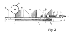
Ein Ausführungsbeispiel des Erfindungsgegenstandes ist in den Zeichnungen dargestellt. Fig. 1 zeigt eine Draufsicht auf eine Palette für Futterteile gemäß der Erfindung. Fig. 2 einen Schrägriß einer solchen Palette und Fig. 3 eine Palette, teilweise im Längsschnitt.An embodiment of the subject of the invention is shown in the drawings. Fig. 1 shows a plan view of a pallet for lining parts according to the invention. Fig. 2 is an oblique view of such a pallet and Fig. 3 is a pallet, partially in longitudinal section.
Gemäß Fig. 1 und 2 sind auf einem Grundrahmen 1 Lager 2 für zwei parallel zueinander angeordnete Spindeln 3 vorgesehen. In den Lagern 2 sind die Spindeln 3 drehbar jedoch axial unverschiebbar gelagert. Die Spindeln 3 verfügen jeweils über ein Linksgewinde 3′ und ein daran anschließendes Rechtsgewinde 3˝. Auf diesen Gewindestücken laufen Muttern 4 und 5, die auf Halteleisten 6, 7 befestigt sind. Bei synchroner Drehung der beiden Spindeln 2 (wenn sie etwa mittels einer Kette 10 auf Kettenrädern verbunden sind) laufen die Halteleisten 6, 7 je nach Drehrichtung zueinander oder auseinander. Die beiden Halteleisten 6, 7 bilden ein Paar. Es sind auf dem Grundrahmen 1 mehrere solcher Halteleistenpaare 6′, 7′; 6˝, 7˝; 6‴, 7‴ vorgesehen. Jeweils die linken Halteleisten 6, 6′, 6˝, 6‴ stehen durch Schienen 8 und jeweils die rechten Halteleisten 7, 7′, 7˝, 7‴ durch Schienen 9 miteinander in starrer Verbindung, sodaß sich zwei in gleicher Ebene ineinandergreifende Gitterrahmen aus Halteleisten ergeben. Diese beiden Gitterrahmen werden durch die beiden Spindeln 3 so gegeneinander verstellt, daß die Mittellinien 11, 11′, 11˝, 11‴ zwischen den Halteleistenpaaren (6, 7; 6′, 7′; 6˝, 7˝; 6‴, 7‴) ortsfest bleiben.1 and 2,
Auf den Halteleisten sind zur Aufnahme von Futterteilen 12 Backen 13 vorgesehen. Für Wellenteile 14 werden Auflagerstücke 15, 16 mit Auflagerschrägen (Fig. 3) paarweise verwendet, die auf den Halteleisten befestigt sind. Wie bekannt,können die auf den Halteleisten erforderlichen Backen, Auflagerstücke od. dgl. auswechselbar bzw. steckbar, angeordnet sein.12
Die Positionen der Werkstücke auf der Palette bleiben unabhängig vom Werkstückdurchmesser immer gleich, weil die Mittellinien parallel zu den beiden Koordinatenrichtungen auch bei Verstellung der Abstände mittels der Spindeln 3 ortsfest sind.The positions of the workpieces on the pallet always remain the same regardless of the workpiece diameter, because the center lines parallel to the two coordinate directions are stationary even when the distances are adjusted by means of the
Claims (4)
Applications Claiming Priority (2)
| Application Number | Priority Date | Filing Date | Title |
|---|---|---|---|
| AT0243987A AT388904B (en) | 1987-09-25 | 1987-09-25 | PALLET FOR PROVIDING, RECEIVING AND TRANSPORTING WORKPIECES |
| AT2439/87 | 1987-09-25 |
Publications (2)
| Publication Number | Publication Date |
|---|---|
| EP0309444A2 true EP0309444A2 (en) | 1989-03-29 |
| EP0309444A3 EP0309444A3 (en) | 1991-06-12 |
Family
ID=3534376
Family Applications (1)
| Application Number | Title | Priority Date | Filing Date |
|---|---|---|---|
| EP19880890248 Withdrawn EP0309444A3 (en) | 1987-09-25 | 1988-09-26 | Pallet for readying, for holding and for transporting work pieces |
Country Status (4)
| Country | Link |
|---|---|
| EP (1) | EP0309444A3 (en) |
| JP (1) | JPH01109050A (en) |
| AT (1) | AT388904B (en) |
| DE (1) | DE8713847U1 (en) |
Cited By (4)
| Publication number | Priority date | Publication date | Assignee | Title |
|---|---|---|---|---|
| EP0416446A1 (en) * | 1989-09-05 | 1991-03-13 | Fritz Schäfer Gesellschaft mit beschränkter Haftung | Making ready, holding and transporting pallet for work pieces |
| DE4207988A1 (en) * | 1992-03-13 | 1993-09-16 | Ford Werke Ag | WORKPIECE MAGAZINE AND DEVICE FOR CONVEYING WORKPIECES IN A DEFINED DELIVERY OR FROM A RECORDING POSITION |
| EP0785144A1 (en) | 1996-01-19 | 1997-07-23 | Xerox Corporation | Pallet system |
| CN101422868B (en) * | 2007-10-31 | 2011-05-04 | 鸿富锦精密工业(深圳)有限公司 | Rolling tool |
Families Citing this family (7)
| Publication number | Priority date | Publication date | Assignee | Title |
|---|---|---|---|---|
| DE8715915U1 (en) * | 1987-12-02 | 1988-01-28 | Calor-Emag Elektrizitaets-Ag, 4030 Ratingen, De | |
| DE3805313A1 (en) * | 1988-02-20 | 1989-08-31 | Kaufmann & Lindgens Gmbh | Device and system for the aligned storage of plate-shaped articles on pallets |
| AT395298B (en) * | 1990-01-11 | 1992-11-10 | Heid Ag Maschf | PALLET FOR PROVIDING, RECEIVING AND TRANSPORTING WORKPIECES |
| DE4128792A1 (en) * | 1991-08-27 | 1993-03-04 | Matec Maschinenbau Und Automat | Positioning element for workpieces - has axial and radial bores with screws for fixing on workpiece supports. |
| DE29818202U1 (en) * | 1998-10-12 | 1999-04-15 | Liebherr Verzahntech Gmbh | Workpiece carrier |
| DE102007014850B4 (en) * | 2007-03-28 | 2023-05-04 | Bayerische Motoren Werke Aktiengesellschaft | production line |
| DE102010063935A1 (en) * | 2010-12-22 | 2012-06-28 | Robert Bosch Gmbh | Saw blade for a jigsaw |
Citations (4)
| Publication number | Priority date | Publication date | Assignee | Title |
|---|---|---|---|---|
| US2662433A (en) * | 1950-02-08 | 1953-12-15 | Caroline A Braun | Device for simultaneously clamping and releasing plural workpieces |
| DE8630262U1 (en) * | 1986-11-12 | 1987-03-19 | Vollmer, Kurt, Dipl.-Ing. (Fh), 7012 Fellbach, De | |
| DD249215A1 (en) * | 1986-05-22 | 1987-09-02 | Werkzeugmasch Okt Veb | SITUATION ELEMENTS FOR PRISMATIC, SHORT ROTATION SYMMETRIC AND WAVEFORM WORKPIECES |
| EP0273798A2 (en) * | 1986-12-01 | 1988-07-06 | Cmb Remy | Device for picking up and holding articles, such as containers, from or at a conveyor equipped with this device |
-
1987
- 1987-09-25 AT AT0243987A patent/AT388904B/en not_active IP Right Cessation
- 1987-10-15 DE DE8713847U patent/DE8713847U1/de not_active Expired
-
1988
- 1988-09-21 JP JP23511288A patent/JPH01109050A/en active Pending
- 1988-09-26 EP EP19880890248 patent/EP0309444A3/en not_active Withdrawn
Patent Citations (4)
| Publication number | Priority date | Publication date | Assignee | Title |
|---|---|---|---|---|
| US2662433A (en) * | 1950-02-08 | 1953-12-15 | Caroline A Braun | Device for simultaneously clamping and releasing plural workpieces |
| DD249215A1 (en) * | 1986-05-22 | 1987-09-02 | Werkzeugmasch Okt Veb | SITUATION ELEMENTS FOR PRISMATIC, SHORT ROTATION SYMMETRIC AND WAVEFORM WORKPIECES |
| DE8630262U1 (en) * | 1986-11-12 | 1987-03-19 | Vollmer, Kurt, Dipl.-Ing. (Fh), 7012 Fellbach, De | |
| EP0273798A2 (en) * | 1986-12-01 | 1988-07-06 | Cmb Remy | Device for picking up and holding articles, such as containers, from or at a conveyor equipped with this device |
Cited By (4)
| Publication number | Priority date | Publication date | Assignee | Title |
|---|---|---|---|---|
| EP0416446A1 (en) * | 1989-09-05 | 1991-03-13 | Fritz Schäfer Gesellschaft mit beschränkter Haftung | Making ready, holding and transporting pallet for work pieces |
| DE4207988A1 (en) * | 1992-03-13 | 1993-09-16 | Ford Werke Ag | WORKPIECE MAGAZINE AND DEVICE FOR CONVEYING WORKPIECES IN A DEFINED DELIVERY OR FROM A RECORDING POSITION |
| EP0785144A1 (en) | 1996-01-19 | 1997-07-23 | Xerox Corporation | Pallet system |
| CN101422868B (en) * | 2007-10-31 | 2011-05-04 | 鸿富锦精密工业(深圳)有限公司 | Rolling tool |
Also Published As
| Publication number | Publication date |
|---|---|
| AT388904B (en) | 1989-09-25 |
| ATA243987A (en) | 1989-02-15 |
| EP0309444A3 (en) | 1991-06-12 |
| DE8713847U1 (en) | 1987-12-03 |
| JPH01109050A (en) | 1989-04-26 |
Similar Documents
| Publication | Publication Date | Title |
|---|---|---|
| DE3320762C2 (en) | Punching machine with a stationary magazine | |
| EP0076231A2 (en) | Method and apparatus for the serial treatment and/or the assembly of workpieces | |
| DE3605470A1 (en) | MULTI-SURFACE MACHINE TOOL | |
| DE10249473A1 (en) | machine tool | |
| EP0908269A2 (en) | Machine tool layout with two machining units arranged facing one another | |
| EP0309444A2 (en) | Pallet for readying, for holding and for transporting work pieces | |
| DE112018000406B4 (en) | PALLET CONVEYOR DEVICE AND METHOD FOR CONVEYING A PALLET | |
| EP0967038B1 (en) | Device for machining by material removal of workpieces | |
| EP1004393A2 (en) | Machine tool arrangment with a device for automatic tool-change | |
| DE60009200T2 (en) | Machine tool for processing symmetrical elongated elements such as, for example, components for chairs, furniture or other such objects | |
| DE1627042B2 (en) | DEVICE WITH AN INDEXABLE WORKPIECE CARRIER AND WITH THIS CONVEYOR RING ON A RING TRANSFER MACHINE | |
| DE4430388A1 (en) | Machine tool carriage setting drive | |
| EP2260975B1 (en) | Surface grinding machine and method for processing workpieces with surface grinding | |
| EP3031572A1 (en) | Tool exchange apparatus for use in a machining centre and machining centre for machining a workpiece | |
| DE4100148C2 (en) | ||
| EP3191376A1 (en) | Flexible workpiece carrier | |
| DD201987A5 (en) | TOOLING MACHINE WITH WORKPIECE SUPPLIERS | |
| DE4137563C1 (en) | Holder for objects of varying dimension - has prismatic bearers with cams sliding in curved grooves, also having curved body moving to give scale reading of object shape | |
| EP0345595A2 (en) | Tool-lamping device for a digitally controlled manufacturing system | |
| DE1777465B1 (en) | Multi-spindle automatic lathe | |
| EP1002623B1 (en) | Device for the feeding of at least one workpiece to a machine tool | |
| DE1552417C3 (en) | Coordinate drilling and milling machine | |
| DE102017126836B4 (en) | processing machine | |
| DD233965A1 (en) | METHOD AND DEVICE FOR FLEXIBLE CHAINING OF MACHINING MACHINES | |
| DE3513471C2 (en) |
Legal Events
| Date | Code | Title | Description |
|---|---|---|---|
| PUAI | Public reference made under article 153(3) epc to a published international application that has entered the european phase |
Free format text: ORIGINAL CODE: 0009012 |
|
| AK | Designated contracting states |
Kind code of ref document: A2 Designated state(s): CH DE GB IT LI |
|
| ITCL | It: translation for ep claims filed |
Representative=s name: STUDIO BIANCHETTI |
|
| GBC | Gb: translation of claims filed (gb section 78(7)/1977) | ||
| PUAL | Search report despatched |
Free format text: ORIGINAL CODE: 0009013 |
|
| AK | Designated contracting states |
Kind code of ref document: A3 Designated state(s): CH DE GB IT LI |
|
| STAA | Information on the status of an ep patent application or granted ep patent |
Free format text: STATUS: THE APPLICATION IS DEEMED TO BE WITHDRAWN |
|
| 18D | Application deemed to be withdrawn |
Effective date: 19911213 |
|
| PGFP | Annual fee paid to national office [announced via postgrant information from national office to epo] |
Ref country code: LU Payment date: 19930719 Year of fee payment: 6 |
|
| EPTA | Lu: last paid annual fee |