EP0309344B1 - Dispositif d'accouplement pour une colonne de direction et véhicule équipé d'un tel dispositif - Google Patents
Dispositif d'accouplement pour une colonne de direction et véhicule équipé d'un tel dispositif Download PDFInfo
- Publication number
- EP0309344B1 EP0309344B1 EP88402379A EP88402379A EP0309344B1 EP 0309344 B1 EP0309344 B1 EP 0309344B1 EP 88402379 A EP88402379 A EP 88402379A EP 88402379 A EP88402379 A EP 88402379A EP 0309344 B1 EP0309344 B1 EP 0309344B1
- Authority
- EP
- European Patent Office
- Prior art keywords
- ring
- yoke
- shaft
- threaded element
- steering column
- Prior art date
- Legal status (The legal status is an assumption and is not a legal conclusion. Google has not performed a legal analysis and makes no representation as to the accuracy of the status listed.)
- Expired - Lifetime
Links
- 230000008878 coupling Effects 0.000 title claims description 15
- 238000010168 coupling process Methods 0.000 title claims description 15
- 238000005859 coupling reaction Methods 0.000 title claims description 15
- 230000003100 immobilizing effect Effects 0.000 claims description 6
- 230000000694 effects Effects 0.000 claims description 4
- 239000013013 elastic material Substances 0.000 claims description 3
- 230000001747 exhibiting effect Effects 0.000 claims 1
- 230000037431 insertion Effects 0.000 claims 1
- 238000003780 insertion Methods 0.000 claims 1
- 230000000903 blocking effect Effects 0.000 description 5
- 240000008042 Zea mays Species 0.000 description 1
- 229920001971 elastomer Polymers 0.000 description 1
- 239000000806 elastomer Substances 0.000 description 1
- 238000012423 maintenance Methods 0.000 description 1
- 239000000463 material Substances 0.000 description 1
Images


Classifications
-
- B—PERFORMING OPERATIONS; TRANSPORTING
- B62—LAND VEHICLES FOR TRAVELLING OTHERWISE THAN ON RAILS
- B62D—MOTOR VEHICLES; TRAILERS
- B62D1/00—Steering controls, i.e. means for initiating a change of direction of the vehicle
- B62D1/02—Steering controls, i.e. means for initiating a change of direction of the vehicle vehicle-mounted
- B62D1/16—Steering columns
-
- F—MECHANICAL ENGINEERING; LIGHTING; HEATING; WEAPONS; BLASTING
- F16—ENGINEERING ELEMENTS AND UNITS; GENERAL MEASURES FOR PRODUCING AND MAINTAINING EFFECTIVE FUNCTIONING OF MACHINES OR INSTALLATIONS; THERMAL INSULATION IN GENERAL
- F16B—DEVICES FOR FASTENING OR SECURING CONSTRUCTIONAL ELEMENTS OR MACHINE PARTS TOGETHER, e.g. NAILS, BOLTS, CIRCLIPS, CLAMPS, CLIPS OR WEDGES; JOINTS OR JOINTING
- F16B41/00—Measures against loss of bolts, nuts, or pins; Measures against unauthorised operation of bolts, nuts or pins
- F16B41/002—Measures against loss of bolts, nuts or pins
-
- F—MECHANICAL ENGINEERING; LIGHTING; HEATING; WEAPONS; BLASTING
- F16—ENGINEERING ELEMENTS AND UNITS; GENERAL MEASURES FOR PRODUCING AND MAINTAINING EFFECTIVE FUNCTIONING OF MACHINES OR INSTALLATIONS; THERMAL INSULATION IN GENERAL
- F16D—COUPLINGS FOR TRANSMITTING ROTATION; CLUTCHES; BRAKES
- F16D1/00—Couplings for rigidly connecting two coaxial shafts or other movable machine elements
- F16D1/06—Couplings for rigidly connecting two coaxial shafts or other movable machine elements for attachment of a member on a shaft or on a shaft-end
- F16D1/08—Couplings for rigidly connecting two coaxial shafts or other movable machine elements for attachment of a member on a shaft or on a shaft-end with clamping hub; with hub and longitudinal key
- F16D1/0852—Couplings for rigidly connecting two coaxial shafts or other movable machine elements for attachment of a member on a shaft or on a shaft-end with clamping hub; with hub and longitudinal key with radial clamping between the mating surfaces of the hub and shaft
- F16D1/0864—Couplings for rigidly connecting two coaxial shafts or other movable machine elements for attachment of a member on a shaft or on a shaft-end with clamping hub; with hub and longitudinal key with radial clamping between the mating surfaces of the hub and shaft due to tangential loading of the hub, e.g. a split hub
-
- F—MECHANICAL ENGINEERING; LIGHTING; HEATING; WEAPONS; BLASTING
- F16—ENGINEERING ELEMENTS AND UNITS; GENERAL MEASURES FOR PRODUCING AND MAINTAINING EFFECTIVE FUNCTIONING OF MACHINES OR INSTALLATIONS; THERMAL INSULATION IN GENERAL
- F16D—COUPLINGS FOR TRANSMITTING ROTATION; CLUTCHES; BRAKES
- F16D3/00—Yielding couplings, i.e. with means permitting movement between the connected parts during the drive
- F16D3/16—Universal joints in which flexibility is produced by means of pivots or sliding or rolling connecting parts
- F16D3/26—Hooke's joints or other joints with an equivalent intermediate member to which each coupling part is pivotally or slidably connected
- F16D3/38—Hooke's joints or other joints with an equivalent intermediate member to which each coupling part is pivotally or slidably connected with a single intermediate member with trunnions or bearings arranged on two axes perpendicular to one another
- F16D3/382—Hooke's joints or other joints with an equivalent intermediate member to which each coupling part is pivotally or slidably connected with a single intermediate member with trunnions or bearings arranged on two axes perpendicular to one another constructional details of other than the intermediate member
- F16D3/387—Fork construction; Mounting of fork on shaft; Adapting shaft for mounting of fork
-
- F—MECHANICAL ENGINEERING; LIGHTING; HEATING; WEAPONS; BLASTING
- F16—ENGINEERING ELEMENTS AND UNITS; GENERAL MEASURES FOR PRODUCING AND MAINTAINING EFFECTIVE FUNCTIONING OF MACHINES OR INSTALLATIONS; THERMAL INSULATION IN GENERAL
- F16D—COUPLINGS FOR TRANSMITTING ROTATION; CLUTCHES; BRAKES
- F16D1/00—Couplings for rigidly connecting two coaxial shafts or other movable machine elements
- F16D1/10—Quick-acting couplings in which the parts are connected by simply bringing them together axially
- F16D2001/102—Quick-acting couplings in which the parts are connected by simply bringing them together axially the torque is transmitted via polygon shaped connections
Definitions
- the present invention essentially relates to a coupling device for a steering column.
- It also relates to a vehicle of any type equipped with such a device.
- the blocking of the shaft in the stirrup is achieved by means of a bolt arranged, and acting on the branches of the stirrup.
- document FR-A-2579 159 has proposed a device in which the bolt screw can be made integral with one of the legs of the stirrup while the nut is in solidarity with the other branch.
- document FR-A-2500 544 describes such a means consisting of a ring screwed onto the threaded element and positively locked on one of the elements to be fixed, said ring then being released during assembly.
- the present invention aims to remedy these drawbacks by proposing an improved coupling device, allowing precise assembly of two elements of a steering column, and ensuring optimum alignment of the screw and the front nut. their commitment to authorize the use of an automatic mounting means such as a robot.
- the invention relates to a device for coupling two elements of a column of steering for example, which comprises a shaft which can be engaged in a stirrup-shaped part, the branches of which can be tightened against the shaft using a bolt comprising a threaded element forming a screw secured to one of the branches of the caliper and a nut-forming element integral with the other branch of the caliper,
- this device being characterized in that it further comprises a ring screwed onto said threaded element as well as a means of immobilizing said ring on the branch of the stirrup which carries the threaded element, said immobilization means being able on the one hand to positively lock the ring on said branch so to put the threaded element in the waiting position before engagement of the shaft in the stirrup, and secondly to allow the unlocking of said ring under the effect of an axial thrust exerted on the threaded element, the ring having a substantially oval shape in cross section to bear, under the effect of the r otation
- the aforementioned ring is housed in a piece forming a trigger guard secured to the branch of the stirrup carrying the threaded element, and provided with means for immobilizing said ring.
- the immobilization means is constituted by a lug made of elastic material acting for example by pressure contact on the periphery of the ring.
- the aforementioned ring is provided with a brake engaged with the thread of the threaded element.
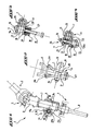
- a coupling device comprises a shaft 1 secured to an upper element 2 of a steering column 3, which is here the lower part 4 of a gimbal 5.
- This shaft 1 can be engaged in a part 6 in the shape of a stirrup secured to a lower element 7 of the steering column 3, which here is a pinion 8 shown in a simplified manner and meshing with a rack, not shown, of a motor vehicle.
- the stirrup 6 has flared ends 6a and 6b arranged in the extension of its sides 11 and 12 allowing easier engagement of the shaft 1 and visible in FIG. 2.
- stirrup-shaped part 6 has two branches 9 and 10 projecting respectively in the extension of the sides 11 and 12 which form the housing 13 receiving the shaft 1.
- These branches transversely comprise a bolt 14 intended to clamp them towards each other in order to block the shaft 1.
- This bolt consists of a first threaded element 15 forming a screw secured to the branch 10 and a second element 16 forming a nut, secured to the branch 9. Note in FIG. 3, representing the threaded element 15 facing the element 16 forming a nut in the waiting position before engagement, that the threaded element 15 cooperates with a ring 17 into which it is screwed. This ring is positively blocked on the branch 10 carrying this element.
- the threaded element 15 is ready to cooperate with the element 16 forming a nut maintained with the element 15 according to a precise axial alignment.
- the ring 17 is housed in a part 18 forming a bridge of substantially cylindrical external shape in which it is made immobile by means of an immobilizing means 19 which is, according to an exemplary embodiment, a lug made of elastic material acting by example by pressure contact on the periphery of the ring 17.
- the part 18 is made integral with the external face of the branch 10 by means of a welded connection 20.
- the ring 17 includes a brake 21, taking the form of an elastomer ring, in engagement with the thread of the element 15 forming a screw.
- This brake 21 keeps the threaded element 15 forming a screw in the ring 17 in its standby position, but also causes the ring 17 to rotate when the element 15 forming a screw cooperates with the element 16 forming a nut.
- the ring 17 is of substantially oval shape in cross section.
- the ring 17 is rotated as explained above and one of its protruding parts 17a or 17b comes into contact against the upper part 1a of the shaft 1 to hold it at the bottom of the stirrup during the blocking phase.
- the shaft 1 is then perfectly positioned in the stirrup 6 and the two elements 4 and 8 are perfectly coaxial.
- the inner part 18a of the trigger guard 18 is a straight groove receiving the ring 17 in a position where the geometric axis 17c of the protruding parts 17a and 17b is always arranged substantially parallel to the geometric axis 1b of the shaft. 1.
- This configuration allows the passage of the ring 17 on the upper part 1a of the shaft 1.
- This groove, as well as the external profile of the part 18 have been shown in dotted lines for a better understanding of the drawings.
- the operation of the coupling device according to the invention is as follows: the shaft 1 is engaged in the housing 13 of the stirrup 6, guided by the free flared ends 6a and 6b.
- the threaded element 15 is pushed by the automatic mounting means, for example a robot, to come into contact with the element 16 forming a nut into which it is then screwed by means of this same mounting means, the ring 17 holding the shaft 1 in position.
- the shaft 1 is made integral with the lower element 7 while the stirrup 6 is made integral with the upper element 5, in particular with the lower part 4 of the gimbal 5.
- FIG 8 there is shown a third embodiment of the coupling device according to the invention.
- the positions of stirrup 6 of shaft 1 have been further modified.
- stirrup 6 is here secured to an upper part 4b of the gimbal 5 now forming the lower element 7 of the steering column 3 while the shaft 1 is made integral with the shaft 3a, now forming the upper element of the steering column 3.
- the trigger guard 18 is produced in the form of a rectangular sheet, shaped then welded on the branch 9, in which the ring 17 is arranged.
- the threaded element 15 is made integral with the branch 9 while the element 16 forming a nut is made integral with the branch 10.
- connection of the element 16 forming a nut on the arms 9 or 10 may be a welded, glued or similar connection, or be an integral part of one of the arms of the stirrup.
- the trigger guard 18 can be fixed on the branch which carries it by means of a welded, glued, or similar connection, or be screwed on the branch which carries it when it is of substantially cylindrical external shape as in the first embodiment of this invention, visible in FIGS. 1 to 4.
- the nut-forming element as well as the trigger guard 18 can be arranged on the inner faces of the branches which carry them if the latter have a recess towards the outside thus increasing the width of the branches.
- the immobilization means 19 can be formed from a rigid material, placed in a housing situated at the periphery of the ring 17, and which can be broken during the movement of this ring.
Landscapes
- Engineering & Computer Science (AREA)
- General Engineering & Computer Science (AREA)
- Mechanical Engineering (AREA)
- Chemical & Material Sciences (AREA)
- Combustion & Propulsion (AREA)
- Transportation (AREA)
- Braking Arrangements (AREA)
- Steering Controls (AREA)
Description
- La présente invention a essentiellement pour objet un dispositif d'accouplement pour une colonne de direction.
- Elle vise également un véhicule d'un type quelconque équipé d'un tel dispositif.
- On connaît déjà des dispositifs d'accouplement permettant l'assemblage de deux éléments et qui comportent une première pièce en forme d'arbre engageable dans une deuxième pièce en forme d'étrier.
- Le blocage de l'arbre dans l'étrier est réalisé par l'intermédiaire d'un boulon disposé, et agissant sur les branches de l'étrier.
- Afin d'obtenir un dispositif unitaire et pratique, on a proposé dans le document FR-A-2579 159 un dispositif dans lequel la vis du boulon peut être rendue solidaire de l'une des branches de l'étrier tandis que l'écrou est solidaire de l'autre branche.
- Cependant, le montage de ces composants sur les branches de l'étrier présente généralement un jeu important et nécessite au cours de l'assemblage un ajustement de la vis sur l'écrou par l'utilisateur. Par ailleurs, pendant cet ajustement, l'arbre doit être maintenu par ce même utilisateur en fond d'étrier afin d'obtenir un alignement précis des éléments à assembler.
- D'autre part, on a déjà décrit pour d'autres applications des moyens pour bloquer un élément fileté en position d'attente avant montage. Par exemple le document FR-A-2500 544 décrit un tel moyen consistant en une bague vissée sur l'élément fileté et positivement bloquée sur l'un des éléments à fixer, ladite bague étant ensuite débloquée lors du montage.
- Toutefois, on ne connaît pas de dispositif d'accouplement pour une colonne de direction où le maintien de l'arbre dans l'étrier est assuré par la bague lors du vissage, de façon à réduire le nombre d'interventions manuelles.
- Par conséquent, tous ces dispositifs connus écartent la possibilité d'utilisation d'un moyen de montage automatique tel qu'un robot.
- Aussi, la présente invention a pour but de remédier à ces inconvénients en proposant un dispositif d'accouplement perfectionné, permettant un assemblage précis de deux éléments d'une colonne de direction, et assurant un alignement optimum de la vis et de l'écrou avant leur engagement afin d'autoriser l'utilisation d'un moyen de montage automatique tel qu'un robot.
- A cet effet, l'invention a pour objet un dispositif d'accouplement de deux éléments d'une colonne de direction par exemple, qui comprend un arbre engageable dans une pièce en forme d'étrier dont les branches peuvent être serrées contre l'arbre à l'aide d'un boulon comportant un élément fileté formant vis solidaire de l'une des branches de l'étrier et un élément formant écrou solidaire de l'autre branche de l'étrier, ce dispositif se caractérisant en ce qu'il comporte en outre une bague vissée sur ledit élément fileté ainsi qu'un moyen d'immobilisation de ladite bague sur la branche de l'étrier qui porte l'élément fileté, ledit moyen d'immobilisation étant apte d'une part à bloquer positivement la bague sur ladite branche pour mettre ainsi l'élément fileté en position d'attente avant engagement de l'arbre dans l'étrier, et d'autre part à permettre le déblocage de ladite bague sous l'effet d'une poussée axiale exercée sur l'élément fileté, la bague présentant une forme sensiblement ovale en section transversale pour prendre appui, sous l'effet de la rotation de l'élément fileté, lors du vissage, contre l'arbre engagé dans l'étrier.
- Suivant une autre caractéristique, la bague précitée est logée dans une pièce formant pontet solidaire de la branche de l'étrier portant l'élément fileté, et munie d'un moyen d'immobilisation de ladite bague.
- On précisera encore ici que le moyen d'immobilisation est constitué par un ergot en matériau élastique agisssant par exemple par contact de pression sur la périphérie de la bague.
- Selon encore une autre caractéristique de cette invention, la bague précitée est munie d'un frein en prise avec le filetage de l'élément fileté.
- Mais d'autres caractéristiques et avantages de l'invention apparaîtront mieux dans la description détaillée qui suit et se réfère aux dessins annexés, donnés à titre d'exemple, et dans lesquels:
- La figure 1 est une vue en coupe longitudinale d'un premier mode de réalisation du dispositif d'accouplement selon l'invention;
- La figure 2 est une vue de côté du dispositif représenté sur la figure 1;
- La figure 3 est une section transversale faite suivant la ligne III-III de la figure 1, avant la phase de blocage;
- La figure 4 est une section transversale identique à la section transversale de la figure 3 mais représentant le dispositif d'accouplement selon l'invention après la phase de blocage;
- La figure 5 est une vue longitudinale d'un deuxième mode de réalisation du dispositif d'accouplement selon l'invention représentant une autre disposition de l'arbre et de l'étrier par rapport à la colonne de direction;
- La figure 6 est une vue de côté du dispositif représenté sur la figure 5;
- La figure 7 est une section transversale faite suivant la ligne VII-VII de la figure 5;
- La figure 8 est une vue en coupe longitudinale d'un troisième mode de réalisation du dispositif d'accouplement selon l'invention représentant entre autres une troisième disposition de l'arbre et de l'étrier sur la colonne de direction;
- La figure 9 est une section transversale faite suivant la ligne IX-IX de la figure 8; et
- La figure 10 est une section transversale faite suivant la ligne X-X de la figure 8 et représentant plus particulièrement les extrémités évasées de l'étrier.
- En se reportant à la figure 1, et suivant un premier mode de réalisation, un dispositif d'accouplement conforme à cette invention comprend un arbre 1 solidaire d'un élément supérieur 2 d'une colonne de direction 3, qui est ici la partie inférieure 4 d'un cardan 5.
- Cet arbre 1 est engageable dans une pièce 6 en forme d'étrier solidaire d'un élément inférieur 7 de la colonne de direction 3, qui est ici un pignon 8 représenté de façon simplifiée et engrenant avec une crémaillère, non représentée, d'un véhicule automobile. L'étrier 6 présente des extrémités 6a et 6b évasées disposées dans le prolongement de ses côtés 11 et 12 permettant un engagement plus facile de l'arbre 1 et visibles sur la figure 2.
- En se reportant aux figures 3 et 4, on remarque que la pièce en forme d'étrier 6 comporte deux branches 9 et 10 faisant saillie respectivement dans le prolongement des côtés 11 et 12 qui forment le logement 13 recevant l'arbre 1.
- Ces branches comportent de façon transversale un boulon 14 destiné à les serrer l'une vers l'autre afin de bloquer l'arbre 1.
- Ce boulon est constitué d'un premier élément fileté 15 formant vis solidaire de la branche 10 et d'un deuxième élément 16 formant écrou, solidaire de la branche 9. On remarque sur la figure 3, représentant l'élément fileté 15 face à l'élément 16 formant écrou en position d'attente avant engagement, que l'élément fileté 15 coopère avec une bague 17 dans laquelle il est vissé. Cette bague est positivement bloquée sur la branche 10 portant cet élément.
- Ainsi, l'élément fileté 15 est prêt à coopérer avec l'élément 16 formant écrou maintenu avec l'élément 15 suivant un alignement axial précis.
- La bague 17 est logée dans une pièce 18 formant pontet de forme extérieure sensiblement cylindrique dans laquelle elle est rendue immobile par l'intermédiaire d'un moyen d'immobilisation 19 qui est, suivant un exemple de réalisation, un ergot en matériau élastique agissant par exemple par contact de pression sur la périphérie de la bague 17.
- La pièce 18 est rendue solidaire de la face extérieure de la branche 10 par l'intermédiaire d'une liaison soudée 20.
- Par ailleurs, la bague 17 comporte un frein 21, revêtant, la forme d'un anneau en élastomère, en prise avec le filetage de l'élément 15 formant vis.
- Ce frein 21 permet de maintenir l'élément fileté 15 formant vis dans la bague 17 dans sa position d'attente, mais aussi d'entraîner en rotation la bague 17 lorsque l'élément 15 formant vis coopère avec l'élément 16 formant écrou.
- Cette action est renforcée par l'action de la face intérieure 9a de la branche 9 de l'étrier 6 qui comprime le frein 21 contre le filetage de l'élément 15 formant vis.
- En se reportant à la figure 1, on remarque que la bague 17 est de forme sensiblement ovale en section transversale.
- Ainsi, lors de la rotation de l'élément fileté 15 dans l'élément 16 formant écrou, la bague 17 est entraînée en rotation comme il a été expliqué ci-dessus et l'une de ses parties protubérantes 17a ou 17b vient en contact contre la partie supérieure 1a de l'arbre 1 pour le maintenir en fond d'étrier lors de la phase de blocage. L'arbre 1 est alors parfaitement positionné dans l'étrier 6 et les deux éléments 4 et 8 sont parfaitement coaxiaux.
- On notera que la partie intérieure 18a du pontet 18 est une rainure droite recevant la bague 17 dans une position où l'axe géométrique 17c des parties protubérantes 17a et 17b est toujours disposé de façon sensiblement parallèle à l'axe géométrique 1b de l'arbre 1. Cette configuration permet le passage de la bague 17 sur la partie supérieure 1a de l'arbre 1. Cette rainure, ainsi que le profil extérieur de la partie 18 ont été représentés en traits pointillés pour une meilleure compréhension des dessins.
- Le fonctionnement du dispositif d'accouplement selon l'invention est le suivant: l'arbre 1 est engagé dans le logement 13 de l'étrier 6, guidé par les extrémités libres évasées 6a et 6b. L'élément fileté 15 est poussé par le moyen de montage automatique, par exemple un robot, pour venir en contact avec l'élément 16 formant écrou dans lequel il est ensuite vissé par l'intermédiaire de ce même moyen de montage, la bague 17 maintenant l'arbre 1 en position.
- En se reportant à la figure 5 où un deuxième mode de réalisation selon l'invention est représenté, les positions de l'arbre 1 et de l'étrier 6 ont été interverties.
- Ainsi, l'arbre 1 est rendu solidaire de l'élément inférieur 7 tandis que l'étrier 6 est rendu solidaire de l'élément supérieur 5, notamment de la partie inférieure 4 du cardan 5.
- En se reportant maintenant à la figure 8, il est représenté un troisième mode de réalisation du dispositif d'accouplement selon l'invention. Les positions de l'étrier 6 de l'arbre 1 ont encore été modifiées.
- En effet, l'étrier 6 est ici solidaire d'une partie supérieure 4b du cardan 5 formant désormais l'élément inférieur 7 de la colonne de direction 3 tandis que l'arbre 1 est rendu solidaire de l'arbre 3a, formant désormais l'élément supérieur de la colonne de direction 3.
- On remarquera de même que les extrémités libres évasées 6a et 6b ont été disposées respectivement dans le prolongement des branches 10 et 9.
- D'autre part, le pontet 18 est réalisé sous la forme d'une feuille rectangulaire, façonnée puis soudée sur la branche 9, dans laquelle est disposée la bague 17.
- Aussi, l'élément fileté 15 est rendu solidaire de la branche 9 tandis que l'élément 16 formant écrou est rendu solidaire de la branche 10.
- On précisera encore ici que la liaison de l'élément 16 formant écrou sur les branches 9 ou 10 peut être une liaison soudée, collée ou analogue, ou être une partie intégrante de l'une des branches de l'étrier.
- Par ailleurs, le pontet 18 peut être fixé sur la branche qui le porte par l'intermédiaire d'une liaison soudée, collée, ou analogue, ou être vissé sur la branche qui le porte lorsqu'il est de forme extérieure sensiblement cylindrique comme dans le premier mode de réalisation de cette invention, visible sur les figures 1 à 4.
- On peut de même remarquer que l'élément formant écrou ainsi que le pontet 18 peuvent être disposés sur les faces intérieures des branches qui les portent si celles-ci présentent un décrochement vers l'extérieur augmentant ainsi la largeur des branches. De même, le moyen d'immobilisation 19 peut être formé d'un matériau rigide, disposé dans un logement situé à la périphérie de la bague 17, et pouvant être brisé lors du déplacement de cette bague.
- Bien entendu, l'invention n'est nullement limitée aux modes de réalisation décrits et illustrés et qui n'ont été donnés qu'à titre d'exemple.
Claims (7)
Applications Claiming Priority (2)
| Application Number | Priority Date | Filing Date | Title |
|---|---|---|---|
| FR8713221A FR2620997B1 (fr) | 1987-09-24 | 1987-09-24 | Dispositif d'accouplement pour une colonne de direction et vehicule equipe d'un tel dispositif |
| FR8713221 | 1987-09-24 |
Publications (2)
| Publication Number | Publication Date |
|---|---|
| EP0309344A1 EP0309344A1 (fr) | 1989-03-29 |
| EP0309344B1 true EP0309344B1 (fr) | 1991-05-08 |
Family
ID=9355186
Family Applications (1)
| Application Number | Title | Priority Date | Filing Date |
|---|---|---|---|
| EP88402379A Expired - Lifetime EP0309344B1 (fr) | 1987-09-24 | 1988-09-21 | Dispositif d'accouplement pour une colonne de direction et véhicule équipé d'un tel dispositif |
Country Status (3)
| Country | Link |
|---|---|
| EP (1) | EP0309344B1 (fr) |
| DE (1) | DE3862729D1 (fr) |
| FR (1) | FR2620997B1 (fr) |
Families Citing this family (13)
| Publication number | Priority date | Publication date | Assignee | Title |
|---|---|---|---|---|
| DE4006787C1 (fr) * | 1990-03-03 | 1991-09-19 | Etablissement Supervis, Vaduz, Li | |
| FR2681389B1 (fr) * | 1991-09-13 | 1994-12-23 | Thomson Csf | Dispositif de guidage et de maintien d'une vis impermeable dans un systeme d'assemblage. |
| DE4202684C1 (fr) * | 1992-01-31 | 1993-07-29 | Etablissement Supervis, Vaduz, Li | |
| US5984790A (en) * | 1997-08-13 | 1999-11-16 | Nsk Ltd. | Universal joint |
| DE19821646B4 (de) * | 1998-05-14 | 2005-06-16 | ZF Lemförder Metallwaren AG | Befestigungssystem |
| US6350078B1 (en) | 1999-09-24 | 2002-02-26 | The Torrington Company | Shaft depressor for a slap yoke in a steering assembly |
| US6443650B2 (en) | 2000-02-03 | 2002-09-03 | Nsk Ltd. | Connection structure of lateral insert type yoke and shaft |
| SE525114C2 (sv) | 2002-06-24 | 2004-11-30 | Hemocue Ab | Passiv optisk komponent, samt system och metod för spektrofotometrisk analys som använder en sådan passiv optisk komponent |
| JP2006097884A (ja) | 2004-08-30 | 2006-04-13 | Nsk Ltd | シャフトと自在継手のヨークとの結合部 |
| JP4483485B2 (ja) | 2004-09-01 | 2010-06-16 | 日本精工株式会社 | シャフトと自在継手のヨークとの結合部 |
| DE102005033627A1 (de) * | 2005-07-19 | 2007-01-25 | GM Global Technology Operations, Inc., Detroit | Vorrichtung zur Verbindung einer Zwischenwelle mit einem Ritzel eines Lenkgetriebes |
| JP4735444B2 (ja) * | 2006-07-04 | 2011-07-27 | 日本精工株式会社 | シャフトと自在継手のヨークとの結合部及びその製造方法 |
| JP6514184B2 (ja) * | 2016-12-27 | 2019-05-15 | フタバ産業株式会社 | 車両用の締結構造体 |
Family Cites Families (5)
| Publication number | Priority date | Publication date | Assignee | Title |
|---|---|---|---|---|
| US2948317A (en) * | 1957-07-01 | 1960-08-09 | Gen Electric | Threaded fastener retaining device with resilient holding means |
| BE755157A (fr) * | 1969-11-17 | 1971-02-01 | Pitner Alfred | Assemblage d'un organe d'accouplement et d'un organe transmetteur de couple |
| US4432680A (en) * | 1981-02-23 | 1984-02-21 | Deutsch Fastener Corp. | Stressed panel fastener |
| JPS6085058A (ja) * | 1983-10-17 | 1985-05-14 | Nippon Plast Co Ltd | 分割カバ−の固着装置 |
| JPS60102524U (ja) * | 1983-12-19 | 1985-07-12 | 日産自動車株式会社 | ステアリング装置 |
-
1987
- 1987-09-24 FR FR8713221A patent/FR2620997B1/fr not_active Expired - Fee Related
-
1988
- 1988-09-21 EP EP88402379A patent/EP0309344B1/fr not_active Expired - Lifetime
- 1988-09-21 DE DE8888402379T patent/DE3862729D1/de not_active Expired - Fee Related
Also Published As
| Publication number | Publication date |
|---|---|
| FR2620997B1 (fr) | 1990-02-02 |
| EP0309344A1 (fr) | 1989-03-29 |
| FR2620997A1 (fr) | 1989-03-31 |
| DE3862729D1 (de) | 1991-06-13 |
Similar Documents
| Publication | Publication Date | Title |
|---|---|---|
| EP0309344B1 (fr) | Dispositif d'accouplement pour une colonne de direction et véhicule équipé d'un tel dispositif | |
| FR2841871A1 (fr) | Pedale de cycle a positionnement axial reglable | |
| FR2780756A1 (fr) | Systeme de blocage a boulon et ecrou | |
| FR2822122A1 (fr) | Assemblage d'un etrier de colonne de direction avec un pignon de direction d'un vehicule automobile | |
| EP2002131A1 (fr) | Ecrou pour la fixation d'un pare-brise d'aeronef et dispositif de fixation d'un pare-brise d'aeronef incorporant ledit ecrou | |
| WO2007115622A1 (fr) | Dispositif de serrage | |
| EP0029475A1 (fr) | Dispositif de serrage ou de blocage d'un objet sur une tige | |
| EP0086691A1 (fr) | Dispositif de fixation des deux ailes d'une chape de dérailleur de pédalier pour bicyclette | |
| EP0189216B1 (fr) | Cadre de tissage | |
| EP1657085A1 (fr) | Agencement pour la liaison entre un capteur angulaire et une barre anti-devers | |
| EP0547945B1 (fr) | Palier de barre de torsion à colliers de serrage | |
| FR2736974A1 (fr) | Attache pour la fixation reglable de deux pieces espacees | |
| EP0802299B1 (fr) | Dispositif d'assemblage en équerre et de bridage entre deux profilés métalliques creux, disposés selon deux directions perpendiculaires | |
| FR2712049A1 (fr) | Dispositif de fixation d'un organe sur un arbre de direction notamment de véhicule automobile. | |
| FR2733285A1 (fr) | Dispositif de fixation mecanique rigide destine a une rotule, ensemble le comprenant et procedes de montage et demontage | |
| EP0679813B1 (fr) | Organe de fixation mécanique de deux éléments l'un à l'autre, notamment pour la fixation d'un carter de direction à un support de direction | |
| FR2799515A1 (fr) | Systeme a rattrapage de jeu pour fixer deux pieces l'une a l'autre au moyen d'un organe de fixation du type a vis | |
| EP1640620B1 (fr) | Dispositif de fixation et de filtration des vibrations, et procédé d'assemblage utilisant ce dispositif pour l'industrie automobile | |
| EP1104736B1 (fr) | Dispositif d'assemblage d'un pignon de direction avec un étrier | |
| FR2711207A1 (fr) | Dispositif de fixation de tuyaux et d'éléments analogues. | |
| FR3029504A1 (fr) | Attache moteur avant d'aeronef | |
| FR2590332A1 (fr) | Dispositif d'assemblage pour tubes ou barres | |
| FR2679285A1 (fr) | Systeme de montage de poignees sur une porte. | |
| FR2812607A1 (fr) | Colonne de direction pour un systeme de direction de vehicule automobile | |
| CA1122833A (fr) | Dispositif de serrage ou de blocage d'un objet sur une tige |
Legal Events
| Date | Code | Title | Description |
|---|---|---|---|
| PUAI | Public reference made under article 153(3) epc to a published international application that has entered the european phase |
Free format text: ORIGINAL CODE: 0009012 |
|
| AK | Designated contracting states |
Kind code of ref document: A1 Designated state(s): DE GB IT |
|
| 17P | Request for examination filed |
Effective date: 19890626 |
|
| 17Q | First examination report despatched |
Effective date: 19900612 |
|
| GRAA | (expected) grant |
Free format text: ORIGINAL CODE: 0009210 |
|
| AK | Designated contracting states |
Kind code of ref document: B1 Designated state(s): DE GB IT |
|
| REF | Corresponds to: |
Ref document number: 3862729 Country of ref document: DE Date of ref document: 19910613 |
|
| ITF | It: translation for a ep patent filed | ||
| GBT | Gb: translation of ep patent filed (gb section 77(6)(a)/1977) | ||
| PLBE | No opposition filed within time limit |
Free format text: ORIGINAL CODE: 0009261 |
|
| STAA | Information on the status of an ep patent application or granted ep patent |
Free format text: STATUS: NO OPPOSITION FILED WITHIN TIME LIMIT |
|
| 26N | No opposition filed | ||
| PGFP | Annual fee paid to national office [announced via postgrant information from national office to epo] |
Ref country code: GB Payment date: 19920911 Year of fee payment: 5 |
|
| PGFP | Annual fee paid to national office [announced via postgrant information from national office to epo] |
Ref country code: DE Payment date: 19921005 Year of fee payment: 5 |
|
| PG25 | Lapsed in a contracting state [announced via postgrant information from national office to epo] |
Ref country code: GB Effective date: 19930921 |
|
| GBPC | Gb: european patent ceased through non-payment of renewal fee |
Effective date: 19930921 |
|
| PG25 | Lapsed in a contracting state [announced via postgrant information from national office to epo] |
Ref country code: DE Effective date: 19940601 |
|
| PG25 | Lapsed in a contracting state [announced via postgrant information from national office to epo] |
Ref country code: IT Free format text: LAPSE BECAUSE OF NON-PAYMENT OF DUE FEES;WARNING: LAPSES OF ITALIAN PATENTS WITH EFFECTIVE DATE BEFORE 2007 MAY HAVE OCCURRED AT ANY TIME BEFORE 2007. THE CORRECT EFFECTIVE DATE MAY BE DIFFERENT FROM THE ONE RECORDED. Effective date: 20050921 |