EP0308760A2 - Steering moment compensation device for braked wheels - Google Patents
Steering moment compensation device for braked wheels Download PDFInfo
- Publication number
- EP0308760A2 EP0308760A2 EP88114876A EP88114876A EP0308760A2 EP 0308760 A2 EP0308760 A2 EP 0308760A2 EP 88114876 A EP88114876 A EP 88114876A EP 88114876 A EP88114876 A EP 88114876A EP 0308760 A2 EP0308760 A2 EP 0308760A2
- Authority
- EP
- European Patent Office
- Prior art keywords
- wheel
- brake
- torque
- steering
- compensation body
- Prior art date
- Legal status (The legal status is an assumption and is not a legal conclusion. Google has not performed a legal analysis and makes no representation as to the accuracy of the status listed.)
- Granted
Links
Images
Classifications
-
- B—PERFORMING OPERATIONS; TRANSPORTING
- B61—RAILWAYS
- B61F—RAIL VEHICLE SUSPENSIONS, e.g. UNDERFRAMES, BOGIES OR ARRANGEMENTS OF WHEEL AXLES; RAIL VEHICLES FOR USE ON TRACKS OF DIFFERENT WIDTH; PREVENTING DERAILING OF RAIL VEHICLES; WHEEL GUARDS, OBSTRUCTION REMOVERS OR THE LIKE FOR RAIL VEHICLES
- B61F5/00—Constructional details of bogies; Connections between bogies and vehicle underframes; Arrangements or devices for adjusting or allowing self-adjustment of wheel axles or bogies when rounding curves
- B61F5/38—Arrangements or devices for adjusting or allowing self- adjustment of wheel axles or bogies when rounding curves, e.g. sliding axles, swinging axles
-
- B—PERFORMING OPERATIONS; TRANSPORTING
- B61—RAILWAYS
- B61C—LOCOMOTIVES; MOTOR RAILCARS
- B61C15/00—Maintaining or augmenting the starting or braking power by auxiliary devices and measures; Preventing wheel slippage; Controlling distribution of tractive effort between driving wheels
- B61C15/14—Maintaining or augmenting the starting or braking power by auxiliary devices and measures; Preventing wheel slippage; Controlling distribution of tractive effort between driving wheels controlling distribution of tractive effort between driving wheels
Definitions
- the invention relates to a device for compensating undesirable steering torques on wheels with brakes of rail vehicles in particular, wherein a turning circumferential force which is proportional to the circumference of a braked wheel and is determined by the circumferential wheel force and steering roller radius is applied to the wheel in question from the outside.
- the known construction cannot come into play if it is a non-driven wheel or if there is no transmission between the drive shaft and the wheel.
- the present design is therefore based on the object, even in this case, when a brake is arranged on the wheel, to obtain a compensation of the steering torque and to provide a device which can be used with any type of brake, such as pad, disc, drum and / or other brakes, e.g. hydro or electrodynamic brakes, work safely and can also be used on small wheels.
- any type of brake such as pad, disc, drum and / or other brakes, e.g. hydro or electrodynamic brakes, work safely and can also be used on small wheels.
- a compensation body is freely rotatable about the wheel axis, on which the reaction torque of a brake with brake shoes or the reaction torque of a hydro- and / or electrodynamic brake is supported, and which on the other hand a known, in both directions of rotation effective and articulated torque support is connected to the axle bridge.
- this device can be used not only with all wheel sizes, but also with any type of brake, provided that it acts on the wheel or on a part connected to the wheel.
- a brake pad 12 is pressed against the wheel tire 13 to brake the wheel 11.
- the wheel 11 is mounted in a known manner with bearings on the steering knuckle 14 so as to be rotatable about the wheel axis, the steering knuckle 14 being mounted in the axle bridge 16 about a swivel axis 14 perpendicular to the wheel axis, which in turn is connected to the chassis frame 23.
- a compensation body 17 is rotatably supported about the wheel axis with bearings and the brake pad 12 is supported on the compensation body 17 via a lever 18.
- a torque support 19 is arranged which is effective in two directions and which consists of a Fork piece 2o, which comprises a ball head 21 which is fixedly arranged on the axle bridge 16 with a lever 22.
- the reaction torque of the brake is transmitted in this way to the axle bridge 16 via the compensation body 17 and the torque support 19.
- This torque support can also consist of two cams, which are arranged on the axle bridge 16, between which a cam attached to the compensation body 17 extends.
- a brake disc 24 is firmly connected to the wheel 11, the brake disc being able to be designed in a known manner as a solid disc or as an internally ventilated disc.
- a divided or undivided brake shoe 25 is attached to either side of the brake disk 24, which is supported by pressure elements such as pressure pistons, brake caliper levers or the like. are pressed against the brake disc 24 when the vehicle is to be braked.
- What is essential here is the fact that the braking reaction force acting on the brake shoes, acting in the circumferential direction, is introduced either directly or via intermediate lever 26 into the compensation body 17, which in turn is via the torque support 19, which consists of a fork 20, which comprises a ball head 21, is articulated to the axle bridge 16.
- the braking reaction torque which is introduced into the compensation body, causes a circumferential force in the active surfaces of the torque support, which generates a compensation torque with its lever arm to the pivot axis of the steering knuckle, which counteracts the steering torque formed from the braking force on the wheel circumference and the steering roller radius.
- the torque support can also be from two intermeshing bevel gears or segments thereof are formed, one gear being connected to the axle bridge 14 and the other bevel gear or a segment thereof being connected to the compensation body 17.
- the invention can be used in all known brake systems, as long as it is ensured that the braking reaction torque is directed to the axle bridge via a compensation body which is freely rotatable in the steering knuckle or in the wheel and an articulated torque support.
- the compensation body does not necessarily have to be mounted in the steering knuckle, but it can also be freely rotated in the wheel about the wheel axis.
Landscapes
- Engineering & Computer Science (AREA)
- Mechanical Engineering (AREA)
- Transportation (AREA)
- Braking Arrangements (AREA)
- Automatic Cycles, And Cycles In General (AREA)
- Steering-Linkage Mechanisms And Four-Wheel Steering (AREA)
Abstract
Description
Die Erfindung betrifft eine Vorrichtung zur Kompensation unerwünschter Lenkmomente an Rädern mit Bremsen von insbesondere Schienenfahrzeugen, wobei ein der am Umfang eines gebremsten Rades wirksamen Radumfangskraft proportionales, durch Radumfangskraft und Lenkrollhalbmesser bestimmtes Wendemoment dem betreffenden Rad von aussen aufgeprägt wird.The invention relates to a device for compensating undesirable steering torques on wheels with brakes of rail vehicles in particular, wherein a turning circumferential force which is proportional to the circumference of a braked wheel and is determined by the circumferential wheel force and steering roller radius is applied to the wheel in question from the outside.
Durch Radumfangskräfte und Lenkrollhalbmesser entstehende Lenkmomente werden bisher weitgehend durch Spurstangen zwischen einander gegenüberliegenden Rädern gegeneinander geschaltet und damit in ihrer Wirkung aufgehoben. Sind jedoch die Lenkmomente an den durch die Spurstangen verbundenen Rädern nicht gleich, können die Momente nur teilweise kompensiert werden. Es wurde daher in DE 35 41 732 A1 vorgeschlagen, eine bei jeder Umfangskraft wirksame Kompensation des Lenkmomentes dadurch zu erreichen, dass das Reaktionsmoment eines im Rad befindlichen Untersetzungsgetriebes über Hebel übertragen und als Kompensationsmoment genutzt wird.Steering torques created by wheel circumferential forces and steering roll radius have so far largely been switched against one another by tie rods between opposing wheels and their effects have thus been canceled. However, if the steering torques on the wheels connected by the tie rods are not the same, the torques can only be partially compensated for. It was therefore proposed in DE 35 41 732 A1 to achieve effective compensation of the steering torque with any circumferential force by transmitting the reaction torque of a reduction gear located in the wheel via levers and using it as a compensation torque.
Die bekannte Konstruktion kann aber dann nicht zum Tragen kommen, wenn es sich um ein nicht-angetriebenes Rad handelt oder wenn zwischen Antriebswelle und Rad kein Getriebe vorhanden ist.However, the known construction cannot come into play if it is a non-driven wheel or if there is no transmission between the drive shaft and the wheel.
Der vorliegenden Konstruktion liegt daher die Aufgabe zugrunde, auch in diesem Fall, wenn eine Bremse am Rad angeordnet ist, eine Kompensation des Lenkmomentes zu erhalten und eine Vorrichtung zu schaffen, welche mit jeder Art Bremse wie Klotz-, Scheiben-, Trommelbremse und/oder anderen Bremsen, z.B. hydro- oder elektrodynamischer Bremse sicher funktioniert und auch bei kleinen Rädern verwendet werden kann.The present design is therefore based on the object, even in this case, when a brake is arranged on the wheel, to obtain a compensation of the steering torque and to provide a device which can be used with any type of brake, such as pad, disc, drum and / or other brakes, e.g. hydro or electrodynamic brakes, work safely and can also be used on small wheels.
Die Lösung der Aufgabe besteht darin, dass im Achsschenkel oder Rad ein Kompensationskörper frei drehbar um die Radachse gelagert ist, an welchem sich einerseits das Reaktionsmoment einer Bremse mit Bremsbacken bzw. das Reaktionsmoment einer hydro- und/oder elektrodynamischen Bremse abstützt, und welcher andererseits über eine an sich bekannte, in beiden Drehrichtungen wirksame und gelenkige Drehmomentabstützung mit der Achsbrücke verbunden ist.The solution to the problem is that in the steering knuckle or wheel, a compensation body is freely rotatable about the wheel axis, on which the reaction torque of a brake with brake shoes or the reaction torque of a hydro- and / or electrodynamic brake is supported, and which on the other hand a known, in both directions of rotation effective and articulated torque support is connected to the axle bridge.
Der Vorteil dieser erfindungsgemässen Vorrichtung liegt vor allem darin, dass die Vorrichtung nicht nur bei allen Radgrössen verwendet werden kann, sondern auch bei jeder Art Bremse, sofern diese auf das Rad oder auf ein mit dem Rad verbundenen Teil wirkt.The advantage of this device according to the invention is above all that the device can be used not only with all wheel sizes, but also with any type of brake, provided that it acts on the wheel or on a part connected to the wheel.
In den Zeichnungen sind beispielsweise Ausführungsformen der Erfindung dargestellt und zwar zeigt :
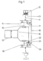
- Figur 1 eine schematische Darstellung, bei der ein Bremsklotz am Radreifen angreift,
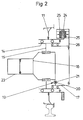
- Figur 2 eine schematische Darstellung, bei der das Rad mit einer Scheibenbremse ausgerüstet ist.
- FIG. 1 shows a schematic illustration in which a brake block acts on the wheel tire,
- Figure 2 is a schematic representation in which the wheel is equipped with a disc brake.
In den Figuren bedeuten gleiche Bezugszeichen gleiche Teile.In the figures, the same reference symbols mean the same parts.
Nach Fig. 1 wird zum Bremsen des Rades 11 ein Bremsklotz 12 gegen den Radreifen 13 gedrückt. Das Rad 11 ist in bekannter Weise mit Lagern auf dem Achsschenkel 14 drehbar um die Radachse gelagert, wobei der Achsschenkel 14 um eine senkrecht zur Radachse stehende Schwenkachse 14 in der Achsbrücke 16 gelagert ist, die wiederum mit dem Fahrwerkrahmen 23 verbunden ist. Im Achsschenkel 14 ist mit Lagern ein Kompensationskörper 17 um die Radachse drehbar gelagert und der Bremsklotz 12 stützt sich über einen Hebel 18 an dem Kompensationskörper 17 ab. Zwischen dem Kompensationskörper 17 und der Achsbrücke 16 ist eine in zwei Richtungen wirksame Drehmomentabstützung 19 angeordnet, welche aus einem Gabelstück 2o besteht, welches einen Kugelkopf 21 umfasst, der mit einem Hebel 22 fest an der Achsbrücke 16 angeordnet ist.Das Reaktionsmoment der Bremse wird auf diese Weise über den Kompensationskörper 17 und die Drehmomentabstützung 19 auf die Achsbrücke 16 übertragen.1, a
Diese Drehmomentabstützung kann aber auch aus zwei Nocken bestehen, welche an der Achsbrücke 16 angeordnet sind, zwischen die sich ein am Kompensationskörper 17 befestigter Nocken erstreckt.This torque support can also consist of two cams, which are arranged on the
In Fig. 2 ist eine andere Art Bremse im Zusammenwirken mit der Erfindung dargestellt. Mit dem Rad 11 ist eine Bremsscheibe 24 festverbunden, wobei die Bremsscheibe in bekannter Weise als Vollscheibe oder als innenbelüftete Scheibe ausgebildet sein kann. Beiderseits der Bremsscheibe 24 sind je eine geteilte oder ungeteilte Bremsbacke 25 angebracht, welche von Druckelementen, wie Druckkolben, Bremszangenhebeln o.ä. an die Bremsscheibe 24 angedrückt werden, wenn das Fahrzeug abgebremst werden soll. Wesentlich hierbei ist die Tatsache, dass die an den Bremsbacken entstehende, in Umfangsrichtung wirkende Bremsreaktionskraft entweder direkt oder über Zwischenhebel 26 in den Kompensationskörper 17 eingeleitet wird, der seinerseits über die Drehmomentabstützung 19, welche aus einer Gabel 2o besteht, die einen Kugelkopf 21 umfasst, mit der Achsbrücke 16 gelenkig verbunden ist.2 shows another type of brake in cooperation with the invention. A
In beiden beschriebenen Ausführungsformen der Erfindung verursacht das Bremsreaktionsmoment, welches in den Kompensationskörper eingeleitet wird, in den Wirkflächen der Drehmomentabstützung eine Umfangskraft, die mit ihrem Hebelarm zur Schwenkachse des Achsschenkels ein Kompensationsmoment erzeugt, welches dem aus Bremskraft am Radumfang und Lenkrollhalbmesser gebildeten Lenkmoment entgegenwirkt.In both described embodiments of the invention, the braking reaction torque, which is introduced into the compensation body, causes a circumferential force in the active surfaces of the torque support, which generates a compensation torque with its lever arm to the pivot axis of the steering knuckle, which counteracts the steering torque formed from the braking force on the wheel circumference and the steering roller radius.
Selbstverständlich kann die Drehmomentabstützung auch von zwei miteinander kämmenden Kegelzahnrädern bzw. Segmenten davon gebildet werden, wobei das eine Zahnrad mit der Achsbrücke 14 und das andere Kegelzahnrad bzw. ein Segment davon mit dem Kompensationskörper 17 verbunden ist.Of course, the torque support can also be from two intermeshing bevel gears or segments thereof are formed, one gear being connected to the
Im Übrigen kann die Erfindung bei allen bekannten Bremssystemen eingesetzt werden, solange gewährleistet ist, dass das Bremsreaktionsmoment über einen im Achsschenkel oder im Rad frei drehbar gelagerten Kompensationskörper und eine gelenkige Drehmomentabstützung auf die Achsbrücke geleitet wird.In addition, the invention can be used in all known brake systems, as long as it is ensured that the braking reaction torque is directed to the axle bridge via a compensation body which is freely rotatable in the steering knuckle or in the wheel and an articulated torque support.
Der Kompensationskörper muss nicht unbedingt im Achsschenkel gelagert sein, sondern er kann auch im Rad frei drehbar um die Radachse gelagert werden.The compensation body does not necessarily have to be mounted in the steering knuckle, but it can also be freely rotated in the wheel about the wheel axis.
Claims (3)
Applications Claiming Priority (2)
| Application Number | Priority Date | Filing Date | Title |
|---|---|---|---|
| DE19873731182 DE3731182A1 (en) | 1987-09-17 | 1987-09-17 | DEVICE FOR STEERING TORQUE COMPENSATION FOR WHEELS WITH BRAKES |
| DE3731182 | 1987-09-17 |
Publications (3)
| Publication Number | Publication Date |
|---|---|
| EP0308760A2 true EP0308760A2 (en) | 1989-03-29 |
| EP0308760A3 EP0308760A3 (en) | 1989-10-25 |
| EP0308760B1 EP0308760B1 (en) | 1994-06-01 |
Family
ID=6336183
Family Applications (1)
| Application Number | Title | Priority Date | Filing Date |
|---|---|---|---|
| EP88114876A Expired - Lifetime EP0308760B1 (en) | 1987-09-17 | 1988-09-12 | Steering moment compensation device for braked wheels |
Country Status (4)
| Country | Link |
|---|---|
| EP (1) | EP0308760B1 (en) |
| AT (1) | ATE106336T1 (en) |
| DE (2) | DE3731182A1 (en) |
| ES (1) | ES2058195T3 (en) |
Families Citing this family (1)
| Publication number | Priority date | Publication date | Assignee | Title |
|---|---|---|---|---|
| DE4216726C2 (en) * | 1992-05-20 | 2001-06-07 | Mannesmann Rexroth Ag | Hydraulic steering for rail vehicles |
Citations (2)
| Publication number | Priority date | Publication date | Assignee | Title |
|---|---|---|---|---|
| DE3538513A1 (en) * | 1987-04-27 | 1987-05-07 | Scheucken Heinrich | Lightweight tram car with steered, driven or idling single-wheel running gear and continuous low-level floor for single-step entry |
| DE3541732A1 (en) * | 1985-11-26 | 1987-05-27 | Duewag Ag | Steering torque compensation |
-
1987
- 1987-09-17 DE DE19873731182 patent/DE3731182A1/en active Granted
-
1988
- 1988-09-12 ES ES88114876T patent/ES2058195T3/en not_active Expired - Lifetime
- 1988-09-12 AT AT88114876T patent/ATE106336T1/en not_active IP Right Cessation
- 1988-09-12 DE DE3889824T patent/DE3889824D1/en not_active Expired - Fee Related
- 1988-09-12 EP EP88114876A patent/EP0308760B1/en not_active Expired - Lifetime
Patent Citations (2)
| Publication number | Priority date | Publication date | Assignee | Title |
|---|---|---|---|---|
| DE3541732A1 (en) * | 1985-11-26 | 1987-05-27 | Duewag Ag | Steering torque compensation |
| DE3538513A1 (en) * | 1987-04-27 | 1987-05-07 | Scheucken Heinrich | Lightweight tram car with steered, driven or idling single-wheel running gear and continuous low-level floor for single-step entry |
Also Published As
| Publication number | Publication date |
|---|---|
| DE3731182A1 (en) | 1989-03-30 |
| DE3889824D1 (en) | 1994-07-07 |
| EP0308760B1 (en) | 1994-06-01 |
| ES2058195T3 (en) | 1994-11-01 |
| DE3731182C2 (en) | 1991-01-17 |
| EP0308760A3 (en) | 1989-10-25 |
| ATE106336T1 (en) | 1994-06-15 |
Similar Documents
| Publication | Publication Date | Title |
|---|---|---|
| DE1625756B2 (en) | PARTIAL DISC BRAKE FOR MOTOR VEHICLES | |
| DE60013319T2 (en) | KNUCKLE | |
| DE8401811U1 (en) | WHEEL BEARING FOR VEHICLES | |
| DE2107519B2 (en) | Independent wheel suspension for motor vehicle wheels with a Tilbelag disc brake | |
| DE19723578C2 (en) | Wheel bearing | |
| DE102017110946A1 (en) | Wheel unit for a vehicle | |
| DE19855275B4 (en) | Partial disc brake in the form of a fixed caliper brake | |
| EP0308760B1 (en) | Steering moment compensation device for braked wheels | |
| DE2635823B2 (en) | Two-part brake carrier for a floating-caliper partially lined disc brake for vehicles | |
| EP0121601B1 (en) | Brake lever for a disc brake | |
| DE3325085C2 (en) | Actuating device for a disc brake | |
| DE69129597T2 (en) | Wheel axle | |
| DE3541732C2 (en) | ||
| DE102007047793A1 (en) | Arrangement for fastening brake device, has wheel carrier with bore holes for receiving depth bolts, where one part of depth bolt serves fastening of brake device and fastening of steering or tracking lever | |
| DE2148797A1 (en) | DEVICE FOR FASTENING THE BRAKE CALIPER OF A DISC BRAKE FOR VEHICLES, IN PARTICULAR FOR MOTOR VEHICLES | |
| DE3310353C2 (en) | Road vehicle with axle steering | |
| DE102004034565A1 (en) | Axle leg or wheel trunk with integrated brake plate for partial disk brake in motor vehicle has inlet contours, primarily supporting braking forces and connected with each other, for brake pads which are arranged on both sides of brake disk | |
| DE8712549U1 (en) | Device for steering torque compensation on wheels with brakes | |
| DE102016223360B4 (en) | Drive arrangement for a vehicle and vehicle with the drive arrangement | |
| EP3710717A1 (en) | Brake arrangement for a utility vehicle | |
| EP0307770B1 (en) | Steering moment compensation device | |
| EP0119466A1 (en) | Spot-type disc brake for vehicles | |
| AT525556B1 (en) | Method for operating a motor vehicle with an electric drive | |
| CH663387A5 (en) | Wheel set for rail vehicles | |
| DE4446465A1 (en) | Motorcycle suspension with negative trail, and lateral elasticity |
Legal Events
| Date | Code | Title | Description |
|---|---|---|---|
| PUAI | Public reference made under article 153(3) epc to a published international application that has entered the european phase |
Free format text: ORIGINAL CODE: 0009012 |
|
| AK | Designated contracting states |
Kind code of ref document: A2 Designated state(s): AT CH DE ES FR GB IT LI NL SE |
|
| PUAL | Search report despatched |
Free format text: ORIGINAL CODE: 0009013 |
|
| AK | Designated contracting states |
Kind code of ref document: A3 Designated state(s): AT CH DE ES FR GB IT LI NL SE |
|
| 17P | Request for examination filed |
Effective date: 19900405 |
|
| 17Q | First examination report despatched |
Effective date: 19901217 |
|
| GRAA | (expected) grant |
Free format text: ORIGINAL CODE: 0009210 |
|
| AK | Designated contracting states |
Kind code of ref document: B1 Designated state(s): AT CH DE ES FR GB IT LI NL SE |
|
| PG25 | Lapsed in a contracting state [announced via postgrant information from national office to epo] |
Ref country code: IT Free format text: LAPSE BECAUSE OF FAILURE TO SUBMIT A TRANSLATION OF THE DESCRIPTION OR TO PAY THE FEE WITHIN THE PRESCRIBED TIME-LIMIT;WARNING: LAPSES OF ITALIAN PATENTS WITH EFFECTIVE DATE BEFORE 2007 MAY HAVE OCCURRED AT ANY TIME BEFORE 2007. THE CORRECT EFFECTIVE DATE MAY BE DIFFERENT FROM THE ONE RECORDED. Effective date: 19940601 Ref country code: FR Effective date: 19940601 |
|
| REF | Corresponds to: |
Ref document number: 106336 Country of ref document: AT Date of ref document: 19940615 Kind code of ref document: T |
|
| REF | Corresponds to: |
Ref document number: 3889824 Country of ref document: DE Date of ref document: 19940707 |
|
| GBT | Gb: translation of ep patent filed (gb section 77(6)(a)/1977) |
Effective date: 19940906 |
|
| PGFP | Annual fee paid to national office [announced via postgrant information from national office to epo] |
Ref country code: SE Payment date: 19941021 Year of fee payment: 7 |
|
| EN | Fr: translation not filed | ||
| REG | Reference to a national code |
Ref country code: ES Ref legal event code: FG2A Ref document number: 2058195 Country of ref document: ES Kind code of ref document: T3 |
|
| EAL | Se: european patent in force in sweden |
Ref document number: 88114876.1 |
|
| PLBE | No opposition filed within time limit |
Free format text: ORIGINAL CODE: 0009261 |
|
| STAA | Information on the status of an ep patent application or granted ep patent |
Free format text: STATUS: NO OPPOSITION FILED WITHIN TIME LIMIT |
|
| 26N | No opposition filed | ||
| PG25 | Lapsed in a contracting state [announced via postgrant information from national office to epo] |
Ref country code: SE Effective date: 19950913 |
|
| EUG | Se: european patent has lapsed |
Ref document number: 88114876.1 |
|
| PGFP | Annual fee paid to national office [announced via postgrant information from national office to epo] |
Ref country code: NL Payment date: 19960930 Year of fee payment: 9 |
|
| PGFP | Annual fee paid to national office [announced via postgrant information from national office to epo] |
Ref country code: GB Payment date: 19970915 Year of fee payment: 10 |
|
| PGFP | Annual fee paid to national office [announced via postgrant information from national office to epo] |
Ref country code: ES Payment date: 19970930 Year of fee payment: 10 |
|
| PG25 | Lapsed in a contracting state [announced via postgrant information from national office to epo] |
Ref country code: NL Free format text: LAPSE BECAUSE OF NON-PAYMENT OF DUE FEES Effective date: 19980401 |
|
| NLV4 | Nl: lapsed or anulled due to non-payment of the annual fee |
Effective date: 19980401 |
|
| PG25 | Lapsed in a contracting state [announced via postgrant information from national office to epo] |
Ref country code: GB Free format text: LAPSE BECAUSE OF NON-PAYMENT OF DUE FEES Effective date: 19980912 |
|
| PG25 | Lapsed in a contracting state [announced via postgrant information from national office to epo] |
Ref country code: ES Free format text: LAPSE BECAUSE OF NON-PAYMENT OF DUE FEES Effective date: 19980913 |
|
| GBPC | Gb: european patent ceased through non-payment of renewal fee |
Effective date: 19980912 |
|
| PGFP | Annual fee paid to national office [announced via postgrant information from national office to epo] |
Ref country code: AT Payment date: 20030829 Year of fee payment: 16 |
|
| PGFP | Annual fee paid to national office [announced via postgrant information from national office to epo] |
Ref country code: CH Payment date: 20030901 Year of fee payment: 16 |
|
| PGFP | Annual fee paid to national office [announced via postgrant information from national office to epo] |
Ref country code: DE Payment date: 20030903 Year of fee payment: 16 |
|
| REG | Reference to a national code |
Ref country code: ES Ref legal event code: FD2A Effective date: 19991013 |
|
| PG25 | Lapsed in a contracting state [announced via postgrant information from national office to epo] |
Ref country code: AT Free format text: LAPSE BECAUSE OF NON-PAYMENT OF DUE FEES Effective date: 20040912 |
|
| PG25 | Lapsed in a contracting state [announced via postgrant information from national office to epo] |
Ref country code: LI Free format text: LAPSE BECAUSE OF NON-PAYMENT OF DUE FEES Effective date: 20040930 Ref country code: CH Free format text: LAPSE BECAUSE OF NON-PAYMENT OF DUE FEES Effective date: 20040930 |
|
| PG25 | Lapsed in a contracting state [announced via postgrant information from national office to epo] |
Ref country code: DE Free format text: LAPSE BECAUSE OF NON-PAYMENT OF DUE FEES Effective date: 20050401 |
|
| REG | Reference to a national code |
Ref country code: CH Ref legal event code: PL |