EP0308666A1 - Knife head for a cutter - Google Patents
Knife head for a cutter Download PDFInfo
- Publication number
- EP0308666A1 EP0308666A1 EP88113721A EP88113721A EP0308666A1 EP 0308666 A1 EP0308666 A1 EP 0308666A1 EP 88113721 A EP88113721 A EP 88113721A EP 88113721 A EP88113721 A EP 88113721A EP 0308666 A1 EP0308666 A1 EP 0308666A1
- Authority
- EP
- European Patent Office
- Prior art keywords
- cutter
- shaft receiving
- toothing
- longitudinal edges
- elongated hole
- Prior art date
- Legal status (The legal status is an assumption and is not a legal conclusion. Google has not performed a legal analysis and makes no representation as to the accuracy of the status listed.)
- Granted
Links
- 230000004323 axial length Effects 0.000 description 2
- 239000000945 filler Substances 0.000 description 2
- 239000000463 material Substances 0.000 description 1
- 230000035515 penetration Effects 0.000 description 1
- 230000007704 transition Effects 0.000 description 1
Images

Classifications
-
- B—PERFORMING OPERATIONS; TRANSPORTING
- B26—HAND CUTTING TOOLS; CUTTING; SEVERING
- B26D—CUTTING; DETAILS COMMON TO MACHINES FOR PERFORATING, PUNCHING, CUTTING-OUT, STAMPING-OUT OR SEVERING
- B26D1/00—Cutting through work characterised by the nature or movement of the cutting member or particular materials not otherwise provided for; Apparatus or machines therefor; Cutting members therefor
- B26D1/01—Cutting through work characterised by the nature or movement of the cutting member or particular materials not otherwise provided for; Apparatus or machines therefor; Cutting members therefor involving a cutting member which does not travel with the work
- B26D1/12—Cutting through work characterised by the nature or movement of the cutting member or particular materials not otherwise provided for; Apparatus or machines therefor; Cutting members therefor involving a cutting member which does not travel with the work having a cutting member moving about an axis
- B26D1/14—Cutting through work characterised by the nature or movement of the cutting member or particular materials not otherwise provided for; Apparatus or machines therefor; Cutting members therefor involving a cutting member which does not travel with the work having a cutting member moving about an axis with a circular cutting member, e.g. disc cutter
-
- B—PERFORMING OPERATIONS; TRANSPORTING
- B02—CRUSHING, PULVERISING, OR DISINTEGRATING; PREPARATORY TREATMENT OF GRAIN FOR MILLING
- B02C—CRUSHING, PULVERISING, OR DISINTEGRATING IN GENERAL; MILLING GRAIN
- B02C18/00—Disintegrating by knives or other cutting or tearing members which chop material into fragments
- B02C18/06—Disintegrating by knives or other cutting or tearing members which chop material into fragments with rotating knives
- B02C18/16—Details
- B02C18/18—Knives; Mountings thereof
- B02C18/20—Sickle-shaped knives
-
- Y—GENERAL TAGGING OF NEW TECHNOLOGICAL DEVELOPMENTS; GENERAL TAGGING OF CROSS-SECTIONAL TECHNOLOGIES SPANNING OVER SEVERAL SECTIONS OF THE IPC; TECHNICAL SUBJECTS COVERED BY FORMER USPC CROSS-REFERENCE ART COLLECTIONS [XRACs] AND DIGESTS
- Y10—TECHNICAL SUBJECTS COVERED BY FORMER USPC
- Y10T—TECHNICAL SUBJECTS COVERED BY FORMER US CLASSIFICATION
- Y10T83/00—Cutting
- Y10T83/929—Tool or tool with support
- Y10T83/9372—Rotatable type
- Y10T83/9374—With spacer interposed between shaft-mounted tools
Definitions
- the invention relates to a cutter head for cutters with at least two cutter knives arranged in mass balance with respect to its axis of rotation, each of which has an elongated hole on the foot side and at least one cutting section, with a shaft receiving disk with a central opening in the form of a regular polygon, and with one on opposite parallel longitudinal edges the shaft receiving disc formed toothing, which is assigned a toothing on opposite parallel longitudinal edges of the cutter knife for the engagement.
- the shaft receiving disks have a longitudinal recess with opposite parallel inner edges which are provided with a toothing.
- the foot of the respective cutter knife can be used in this longitudinal recess and is provided with a corresponding toothing on its opposite parallel outer longitudinal edges. This toothing allows a radial knife adjustment to be achieved, but the axial length of the knife head is very large, since the shaft receiving disk with half its thickness is present between two axially adjacent cutter knives.
- the object on which the invention is based is to design the cutter head of the generic type in such a way that a form-fitting, radially adjustable positioning and secure holding of the cutter knife of the cutter head is ensured even if the cutter knives are arranged axially directly against one another.
- the toothing of the shaft receiving disc is formed on its outer longitudinal edges and the toothing on the cutter knife on the longitudinal edges of its elongated hole, that the thickness of the shaft receiving disc is not greater than the depth of the elongated hole in the cutter knife , and that the outer longitudinal edges of the shaft receiving disc are shorter than the longitudinal edges of the elongated hole.
- the cutter knives can be adjusted in the radial direction according to the tooth pitch, taking into account the required mass balancing, and fixed with respect to the drive shaft, the cutter knives being able to be arranged axially directly against one another in order to achieve the minimum axial overall length, since the shaft receiving disk is in the slot of the assigned cutter knife is recorded and corresponds in its thickness to the depth of the elongated hole substantially.
- the cutter knives are fixed on the drive shaft through the appropriately designed opening in the shaft receiving disk, the cutter knives can be made larger on the foot side, as a result of which a larger clamping surface and thus a more stable mounting on the drive shaft can be achieved.
- the risk of knife breakage is reduced due to the large cross section during the transition to the cutting section.
- the shaft receiving disks can be square, so that toothings with a different pitch can also be attached to the transverse edges, which enables a radial infeed of, for example, 3 mm, 1.5 mm and 0.75 mm.
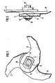
- the cutter head shown in Fig. 1 and 2 consists of three cutter knives A, B and C, which are arranged in an angular position of 120 ° to each other on a drive shaft 9 'axially directly adjacent and secured to the shaft head 13 by a lock nut 12.
- the cutter knife 1 shown in detail in FIG. 3 corresponds in its design to the cutter knife A, B or C from FIG. 1.
- the cutter knife 1 has cutting sections 2, 3, 4 and 5.
- In the area of the knife foot 6 there is an elongated hole 7 with opposing ones parallel inner longitudinal edges formed, which are provided with an internal toothing 10.
- a shaft receiving disc 8 with a central hexagonal opening 9 for receiving a drive shaft 9 'with a corresponding hexagon profile has on its opposite parallel outer longitudinal edges an external toothing 11 which is designed for engagement with the toothing 10 on the longitudinal edges of the elongated hole 7, whereby a radial adjustment of the cutter knife 1 with respect to the central opening 9 of the shaft receiving disk 8 and thus with respect to the drive shaft 9 'around the tooth pitch provided is possible.
- the longitudinal extent of the shaft receiving disc 8 is less than the extension of the elongated hole 7 in its longitudinal direction in order to ensure the radial adjustment over a certain longitudinal range, which is required by regrinding and balanced positioning of the cutter knife.
- the thickness of the shaft receiving disk 8 corresponds essentially to the thickness of the cutter knife 1 in the area of its knife base 6, i.e. the depth of the elongated hole 7, so that when the shaft receiving disk 8 is arranged in the respective cutter knife 1 or A, B and C, the cutter head consists of compact components lying next to each other.
Landscapes
- Engineering & Computer Science (AREA)
- Food Science & Technology (AREA)
- Life Sciences & Earth Sciences (AREA)
- Forests & Forestry (AREA)
- Mechanical Engineering (AREA)
- Knives (AREA)
- Crushing And Pulverization Processes (AREA)
- Harvester Elements (AREA)
- Transition And Organic Metals Composition Catalysts For Addition Polymerization (AREA)
- Window Of Vehicle (AREA)
- Details Of Cutting Devices (AREA)
- Processing And Handling Of Plastics And Other Materials For Molding In General (AREA)
- Nonmetal Cutting Devices (AREA)
- Finish Polishing, Edge Sharpening, And Grinding By Specific Grinding Devices (AREA)
- Shovels (AREA)
- Threshing Machine Elements (AREA)
- Processing Of Stones Or Stones Resemblance Materials (AREA)
- Optical Elements Other Than Lenses (AREA)
- Optical Communication System (AREA)
- Aerials With Secondary Devices (AREA)
- Cutting Tools, Boring Holders, And Turrets (AREA)
- Food-Manufacturing Devices (AREA)
- Control And Other Processes For Unpacking Of Materials (AREA)
Abstract
Um die Kuttermesser (1; A, B, C) eines Messerkopfes auf einfache Weise auf geringstem axialen Raum radial einstellbar positionieren zu können, wird in einem Langloch (7) im Bereich des Messerfusses (6) an dessen parallelen gegenüberliegenden inneren Längsrändern eine Verzahnung (10) ausgebildet, in die eine Verzahnung (11) an parallelen gegenüberliegenden äußeren Längsrändern einer Wellenaufnahmescheibe (8) eingreift, die eine zentrale Öffnung (9) aufweist, deren Form dem Querschnitt einer Treibwelle (9') entspricht. Die Dicke der Wellenaufnahmescheibe (8) ist dabei nicht größer als die Tiefe des Langlochs (7), während aber die Länge der Wellenaufnahmescheibe (8) kleiner ist als die Längserstreckung des Langlochs (7).In order to be able to position the cutter knives (1; A, B, C) of a cutter head in a radially adjustable manner in the smallest of axial spaces in a simple manner, a toothing () is provided in an elongated hole (7) in the area of the knife base (6) on its parallel, opposite longitudinal longitudinal edges. 10), into which a toothing (11) engages on parallel opposite outer longitudinal edges of a shaft receiving disc (8), which has a central opening (9), the shape of which corresponds to the cross section of a drive shaft (9 '). The thickness of the shaft receiving disk (8) is not greater than the depth of the elongated hole (7), but the length of the shaft receiving disk (8) is smaller than the longitudinal extent of the elongated hole (7).
Description
Die Erfindung betrifft einen Messerkopf für Kutter mit wenigstens zwei im Massenausgleich bezüglich seiner Drehachse angeordneten Kuttermessern, von denen jedes ein fußseitiges Langloch und wenigstens einen Schneidenabschnitt aufweist, mit einer Wellenaufnahmescheibe mit einer zentralen Öffnung in Form eines regelmäßigen Vielecks, und mit einer an gegenüberliegenden parallelen Längsrändern der Wellenaufnahmescheibe ausgebildeten Verzahnung, der für den Eingriff eine Verzahnung an gegenüberliegenden parallelen Längsrändern des Kuttermessers zugeordnet ist.The invention relates to a cutter head for cutters with at least two cutter knives arranged in mass balance with respect to its axis of rotation, each of which has an elongated hole on the foot side and at least one cutting section, with a shaft receiving disk with a central opening in the form of a regular polygon, and with one on opposite parallel longitudinal edges the shaft receiving disc formed toothing, which is assigned a toothing on opposite parallel longitudinal edges of the cutter knife for the engagement.
Bei dem solchen, aus der DE-C-2 027 429 bekannten Messerkopf haben die Wellenaufnahmescheiben eine Längsaussparung mit gegenüberliegenden parallelen Innenrändern, die mit einer Verzahnung versehen sind. In dieser Längsaussparung ist der Fuß des jeweiligen Kuttermessers einsetzbar, das an seinen gegenüberliegenden parallelen äußeren Längsrändern mit einer entsprechenden Verzahnung versehen ist. Durch diese Verzahnung läßt sich zwar eine radiale Messerverstellung erreichen, jedoch ist die axiale Länge des Messerkopfes sehr groß, da zwischen zwei axial benachbarten Kuttermessern die Wellenaufnahmescheibe mit ihrer halben Dicke vorhanden ist. Wenn für einen bestimmten Kutter nun ein Messerkopf gebraucht werden kann, dessen axiale Gesamtlänge die Positionierung solcher Wellenaufnahmescheiben zwischen den Kuttermessern nicht mehr zuläßt, muß die durch die Verzahnung mögliche radiale Einstellung und sichere Halterung aufgegeben und eine komplizierte Verspannung mit Spannschrauben und Muttern verwendet werden.In the case of the cutter head known from DE-C-2 027 429, the shaft receiving disks have a longitudinal recess with opposite parallel inner edges which are provided with a toothing. The foot of the respective cutter knife can be used in this longitudinal recess and is provided with a corresponding toothing on its opposite parallel outer longitudinal edges. This toothing allows a radial knife adjustment to be achieved, but the axial length of the knife head is very large, since the shaft receiving disk with half its thickness is present between two axially adjacent cutter knives. If a cutter head can now be used for a particular cutter whose overall axial length no longer allows the positioning of such shaft mounting disks between the cutter knives, the radial adjustment and secure mounting possible through the toothing must be abandoned and a complicated bracing with clamping screws and nuts used.
Die der Erfindung zugrundeliegende Aufgabe besteht nun darin, den Messerkopf der gattungsgemäßen Art so auszubilden, daß eine formschlüssige radial verstellbare Positionierung und sichere Halterung der Kuttermesser des Messerkopfes auch dann gewährleistet ist, wenn die Kuttermesser axial direkt aneinander angeordnet werden.The object on which the invention is based is to design the cutter head of the generic type in such a way that a form-fitting, radially adjustable positioning and secure holding of the cutter knife of the cutter head is ensured even if the cutter knives are arranged axially directly against one another.
Diese Aufgabe wird bei dem Messerkopf der gattungsgemäßen Art dadurch gelöst, daß die Verzahnung der Wellenaufnahmescheibe an deren äußeren Längsrändern und die Verzahnung am Kuttermesser an den Längsrändern seines Langlochs ausgebildet ist, daß die Dicke der Wellenaufnahmescheibe nicht größer ist als die Tiefe des Langlochs in dem Kuttermesser, und daß die äußeren Längsränder der Wellenaufnahmescheibe kürzer sind als die Längsränder des Langlochs.This object is achieved in the cutter head of the generic type in that the toothing of the shaft receiving disc is formed on its outer longitudinal edges and the toothing on the cutter knife on the longitudinal edges of its elongated hole, that the thickness of the shaft receiving disc is not greater than the depth of the elongated hole in the cutter knife , and that the outer longitudinal edges of the shaft receiving disc are shorter than the longitudinal edges of the elongated hole.
Aus der DE-C-738 472 ist es zwar bekannt, bei einem Kuttermesser mit einer rechteckigen Aussparung im Messerfuß für das Einschieben einer quadratischen Treibwelle am offenen Ende der Aussparung an den Innenrändern eine Verzahnung vorzusehen, in die eine gleich starke Füllplatte mit ihrer Außenverzahnung eingreift, um dadurch eine Verstell- und Sicherungsmöglichkeit zu gewährleisten. Es handelt sich dabei jedoch lediglich um ein Verschlußteil an der Aussparung, um das Eindringen von im Kutter zerkleinerten Material in schwer zu reinigende Bereiche zu verhindern, da davon auszugehen ist, daß bei stärkeren Belastungen am Messerfuß sich die Enden der Aussparung aufbiegen, so daß die Haltewirkung der Welle durch die Füllplatte in Frage gestellt ist.From DE-C-738 472 it is known to provide a toothing in a cutter knife with a rectangular recess in the knife base for inserting a square drive shaft at the open end of the recess on the inner edges, in which an equally strong filler plate engages with its outer toothing to ensure adjustment and securing options. However, it is only a closure part on the recess to prevent the penetration of material shredded in the cutter into areas that are difficult to clean, since it can be assumed that the ends of the recess bend open under heavy loads on the knife base, so that the Holding effect of the shaft is questioned by the filler plate.
Bei dem erfindungsgemäßen Messerkopf lassen sich die Kuttermesser unter Berücksichtigung des erforderlichen Massenausgleichs in radialer Richtung entsprechend der Verzahnungsteilung einstellen und bezüglich der Treibwelle fixieren, wobei zur Erzielung der minimalen axialen Baulänge die Kuttermesser axial direkt aneinander anliegend angeordnet werden können, da die Wellenaufnahmescheibe in dem Langloch des zugeordneten Kuttermessers aufgenommen ist und in ihrer Dicke der Tiefe des Langlochs im wesentlichen entspricht.In the cutter head according to the invention, the cutter knives can be adjusted in the radial direction according to the tooth pitch, taking into account the required mass balancing, and fixed with respect to the drive shaft, the cutter knives being able to be arranged axially directly against one another in order to achieve the minimum axial overall length, since the shaft receiving disk is in the slot of the assigned cutter knife is recorded and corresponds in its thickness to the depth of the elongated hole substantially.
Da die Fixierung der Kuttermesser auf der Treibwelle durch die entsprechend gestaltete Öffnung in der Wellenaufnahmescheibe gewährleistet ist, können die Kuttermesser fußseitig größer ausgebildet werden, wodurch eine größere Spannfläche und dadurch eine stabilere Halterung auf der Treibwelle erreichbar sind. Außerdem wird durch den großen Querschnitt bei dem Übergang in den Schneidabschnitt die Messerbruchgefahr verringert. Schließlich können die Wellenaufnahmescheiben quadratisch ausgebildet werden, so daß auch an den Querrändern Verzahnungen mit anderer Teilung angebracht werden können, was eine radiale Zustellung von beispielsweise 3 mm, 1,5 mm und 0,75 mm ermöglicht.Since the cutter knives are fixed on the drive shaft through the appropriately designed opening in the shaft receiving disk, the cutter knives can be made larger on the foot side, as a result of which a larger clamping surface and thus a more stable mounting on the drive shaft can be achieved. In addition, the risk of knife breakage is reduced due to the large cross section during the transition to the cutting section. Finally, the shaft receiving disks can be square, so that toothings with a different pitch can also be attached to the transverse edges, which enables a radial infeed of, for example, 3 mm, 1.5 mm and 0.75 mm.
Anhand von Zeichnungen wird ein Auführungsbeispiel der Erfindung näher erläutert. Es zeigt:
- Fig. 1 eine Draufsicht auf einen Messerkopf mit drei Kuttermessern und geschnittener Treibwelle,
- Fig. 2 eine Seitenansicht des Messerkopfes von Fig. 1 und
- Fig. 3 eine Draufsicht auf das vorderste Kuttermesser des Messerkopfes von Fig. 1.
- 1 is a plan view of a cutter head with three cutter knives and a cut drive shaft,
- Fig. 2 is a side view of the cutter head of Fig. 1 and
- Fig. 3 is a plan view of the foremost cutter knife of the cutter head of FIG. 1.
Der in Fig. 1 und 2 gezeigte Messerkopf besteht aus drei Kuttermessern A, B und C, die in einer Winkelstellung von jeweils 120° zueinander auf einer Treibwelle 9′ axial direkt aneinanderliegend angeordnet und am Wellenkopf 13 durch eine Sicherungsmutter 12 gesichert sind.The cutter head shown in Fig. 1 and 2 consists of three cutter knives A, B and C, which are arranged in an angular position of 120 ° to each other on a drive shaft 9 'axially directly adjacent and secured to the shaft head 13 by a lock nut 12.
Das in Fig. 3 im einzelnen gezeigt Kuttermesser 1 entspricht in seiner Ausgestaltung dem Kuttermesser A, B oder C von Fig. 1. Das Kuttermesser 1 hat Schneidenabschnitte 2, 3, 4 und 5. Im Bereich des Messerfusses 6 ist ein Langloch 7 mit gegenüberliegenden parallelen inneren Längsrändern ausgebildet, die mit einer Innenverzahnung 10 versehen sind.The cutter knife 1 shown in detail in FIG. 3 corresponds in its design to the cutter knife A, B or C from FIG. 1. The cutter knife 1 has cutting sections 2, 3, 4 and 5. In the area of the knife foot 6 there is an elongated hole 7 with opposing ones parallel inner longitudinal edges formed, which are provided with an
Eine Wellenaufnahmescheibe 8 mit einer zentralen sechseckigen Öffnung 9 für die Aufnahme einer Treibwelle 9′ mit entsprechendem Sechskantprofil weist an ihren gegenüberliegenden parallelen äußeren Längsrändern eine Außenverzahnung 11 auf, die für den Eingriff mit der Verzahnung 10 an den Längsrändern des Langlochs 7 ausgebildet ist, wodurch eine radiale Einstellung des Kuttermessers 1 bezüglich der zentralen Öffnung 9 der Wellenaufnahmescheibe 8 und somit bezüglich der Treibwelle 9′ um die vorgesehene Zahnteilung möglich ist.A shaft receiving
Die Längserstreckung der Wellenaufnahmescheibe 8 ist geringer als die Ausdehnung des Langlochs 7 in seiner Längsrichtung, um die radiale Nachstellung über einen bestimmten Längsbereich zu gewährleisten, die durch Nachschleifen und ausgewuchtetes Positionieren der Kuttermesser erforderlich wird.The longitudinal extent of the shaft receiving
Die Dicke der Wellenaufnahmescheibe 8 entspricht im wesentlichen der Dicke des Kuttermessers 1 im Bereich seines Messerfusses 6, also der Tiefe des Langlochs 7, so daß, wenn die Wellenaufnahmescheibe 8 in dem jeweiligen Kuttermesser 1 bzw. A, B and C angeordnet ist, der Messerkopf aus kompakt aneinanderliegenden Bauelementen besteht.The thickness of the shaft receiving
Claims (1)
Priority Applications (1)
| Application Number | Priority Date | Filing Date | Title |
|---|---|---|---|
| AT88113721T ATE59581T1 (en) | 1987-09-24 | 1988-08-23 | KNIFE HEAD FOR CUTTER. |
Applications Claiming Priority (2)
| Application Number | Priority Date | Filing Date | Title |
|---|---|---|---|
| DE3732237A DE3732237C1 (en) | 1987-09-24 | 1987-09-24 | Cutter head for cutters |
| DE3732237 | 1987-09-24 |
Publications (2)
| Publication Number | Publication Date |
|---|---|
| EP0308666A1 true EP0308666A1 (en) | 1989-03-29 |
| EP0308666B1 EP0308666B1 (en) | 1991-01-02 |
Family
ID=6336814
Family Applications (1)
| Application Number | Title | Priority Date | Filing Date |
|---|---|---|---|
| EP88113721A Expired - Lifetime EP0308666B1 (en) | 1987-09-24 | 1988-08-23 | Knife head for a cutter |
Country Status (25)
| Country | Link |
|---|---|
| US (1) | US4930709A (en) |
| EP (1) | EP0308666B1 (en) |
| JP (1) | JPS6490047A (en) |
| KR (1) | KR910009398B1 (en) |
| CN (1) | CN1005898B (en) |
| AT (1) | ATE59581T1 (en) |
| BG (1) | BG51240A3 (en) |
| BR (1) | BR8803886A (en) |
| CA (1) | CA1290682C (en) |
| CZ (1) | CZ277977B6 (en) |
| DD (1) | DD273580A5 (en) |
| DE (2) | DE3732237C1 (en) |
| DK (1) | DK161679C (en) |
| ES (1) | ES2019443B3 (en) |
| FI (1) | FI87742C (en) |
| GR (1) | GR3001285T3 (en) |
| HU (1) | HU198637B (en) |
| LT (1) | LT2044B (en) |
| LV (1) | LV5196A3 (en) |
| MX (1) | MX170429B (en) |
| NZ (1) | NZ226244A (en) |
| RO (1) | RO101979A2 (en) |
| SK (1) | SK277882B6 (en) |
| SU (1) | SU1687024A3 (en) |
| YU (1) | YU47707B (en) |
Cited By (9)
| Publication number | Priority date | Publication date | Assignee | Title |
|---|---|---|---|---|
| FR2799992A1 (en) * | 1999-10-25 | 2001-04-27 | Hotimsky Eric R L | Mounting device for adjusting, locking and balancing cutter machine blades used in food industries includes blades having notch held in position by wedges on driving square and balanced by counterweights on adjustment bench |
| WO2007048390A1 (en) * | 2005-10-28 | 2007-05-03 | Knecht Maschinenbau Gmbh | Meat cutter |
| CN102284969A (en) * | 2011-07-14 | 2011-12-21 | 韩双慧 | Turntable type potato slicing machine |
| CN103706446A (en) * | 2014-01-02 | 2014-04-09 | 李明科 | Rapid 7-shaped cutter mounting base of wood crusher |
| US11583144B1 (en) | 2022-05-18 | 2023-02-21 | Sharkninja Operating Llc | Micro puree machine with partial depth processing |
| US11617474B1 (en) | 2022-05-18 | 2023-04-04 | Sharkninja Operating Llc | Lid and blade assembly for a micro puree machine |
| USD1021533S1 (en) | 2022-05-09 | 2024-04-09 | Sharkninja Operating Llc | User interface for a micro puree machine |
| USD1021520S1 (en) | 2022-05-09 | 2024-04-09 | Sharkninja Operating Llc | Housing for a micro puree machine |
| USD1033134S1 (en) | 2022-07-05 | 2024-07-02 | Sharkninja Operating Llc | Blade for a micro puree machine |
Families Citing this family (25)
| Publication number | Priority date | Publication date | Assignee | Title |
|---|---|---|---|---|
| US6527207B1 (en) | 1998-05-14 | 2003-03-04 | James J. Farrell | Cutting device and method for cutting material from a container |
| US20050086814A1 (en) * | 2003-10-27 | 2005-04-28 | Hsin-Fu Huang | Cutter of juicer |
| US7404883B2 (en) * | 2004-04-12 | 2008-07-29 | Robert Bosch Gmbh | Insulation bushing assembly for an exhaust gas sensor |
| AU2004319016A1 (en) * | 2004-04-29 | 2005-11-10 | Recuperacion Materiales Diversos, S.A. | Shredder for the shredding of recyclable industrial waste |
| CN101332055A (en) * | 2006-12-19 | 2008-12-31 | 康奈尔公司 | Food processor |
| EP2062646A3 (en) | 2007-11-21 | 2017-07-12 | GW Steffens GmbH | Cutter knife and knife head equipped with same |
| DE102007056124A1 (en) | 2007-11-21 | 2009-05-28 | G. Walter Steffens Gmbh & Co. Kg | Cutter knife for e.g. sausage meat, has outward curved blade and inward curved rear blade with grinds that lie on same side of corrugated blade, where size of corrugated blade is reduced by bevel running on side of corrugated blade |
| ES2504069T3 (en) * | 2011-08-25 | 2014-10-08 | Electrolux Professionel Sas | Cutting disc for cutting food and corresponding apparatus |
| CN102794295B (en) * | 2012-07-25 | 2014-11-19 | 中国环境科学研究院 | Horizontal type continuous separating and spin-drying device for aluminum plastic composite packing material |
| USD702085S1 (en) | 2013-03-01 | 2014-04-08 | Euro-Pro Operating Llc | Blade assembly |
| CN107440559B (en) * | 2017-08-14 | 2023-06-13 | 江门市江海区柏健电器制造有限公司 | Mixer knife rest structure with inclined blade |
| IT201900006950A1 (en) | 2019-05-17 | 2020-11-17 | Waste Processing Tech Srl | Rotor of waste shredder apparatus and apparatus incorporating said rotor |
| USD905496S1 (en) | 2019-11-25 | 2020-12-22 | Blendjet Inc. | Portable blender |
| USD908428S1 (en) | 2019-12-02 | 2021-01-26 | Blendjet Inc. | Removable jar of a portable blender |
| USD911107S1 (en) | 2019-12-09 | 2021-02-23 | Blendjet Inc. | Button and light ring of a portable blender |
| USD927931S1 (en) * | 2020-04-06 | 2021-08-17 | Prc-Desoto International, Inc. | Mixing impeller |
| US11531403B2 (en) | 2020-10-06 | 2022-12-20 | Blendjet Inc. | One button interface of a blender |
| USD981179S1 (en) | 2020-11-20 | 2023-03-21 | Blendjet Inc. | Base of a battery-powered portable blender |
| USD1007947S1 (en) | 2020-11-20 | 2023-12-19 | Blendjet Inc. | Battery-powered portable blender |
| USD1007948S1 (en) | 2020-11-25 | 2023-12-19 | Blendjet Inc. | Removable jar of a battery-powered portable blender |
| USD1014178S1 (en) | 2020-11-25 | 2024-02-13 | Blendjet Inc. | Battery-powered portable blender |
| US11690482B1 (en) | 2020-12-10 | 2023-07-04 | Blendjet Inc. | Power boost mode for a blender |
| USD974841S1 (en) * | 2021-03-08 | 2023-01-10 | Blendjet Inc. | Blade assembly for a portable blender |
| US11824365B2 (en) | 2021-03-08 | 2023-11-21 | Blendjet Inc. | Portable blender with wireless charging |
| USD1028611S1 (en) | 2022-04-11 | 2024-05-28 | Blendjet Inc. | Portable blender lid |
Citations (2)
| Publication number | Priority date | Publication date | Assignee | Title |
|---|---|---|---|---|
| GB594588A (en) * | 1945-02-05 | 1947-11-14 | B & P Swift Ltd | An improved drive and method of mounting of knives or cutters for chopping or mincing machines |
| DE2027429A1 (en) * | 1970-06-04 | 1971-12-30 | Karpf, Josef, 8135 Söcking | Cutting tool for cutter |
Family Cites Families (4)
| Publication number | Priority date | Publication date | Assignee | Title |
|---|---|---|---|---|
| DE223771C (en) * | ||||
| DE738472C (en) * | 1941-03-05 | 1943-08-17 | P & S Plum As | Sickle-shaped cutter knife |
| US3491818A (en) * | 1967-04-27 | 1970-01-27 | Hobam Inc | Knife assembly for meat cutting machine |
| DE2310997C3 (en) * | 1973-03-06 | 1985-02-21 | G. Walter 5630 Remscheid Steffens | Cutter head for cutter |
-
1987
- 1987-09-24 DE DE3732237A patent/DE3732237C1/en not_active Expired
-
1988
- 1988-03-08 JP JP63052780A patent/JPS6490047A/en active Granted
- 1988-08-05 BR BR8803886A patent/BR8803886A/en not_active IP Right Cessation
- 1988-08-09 KR KR1019880010146A patent/KR910009398B1/en not_active IP Right Cessation
- 1988-08-23 ES ES88113721T patent/ES2019443B3/en not_active Expired - Lifetime
- 1988-08-23 AT AT88113721T patent/ATE59581T1/en active
- 1988-08-23 DE DE8888113721T patent/DE3861369D1/en not_active Expired - Fee Related
- 1988-08-23 EP EP88113721A patent/EP0308666B1/en not_active Expired - Lifetime
- 1988-08-30 US US07/238,559 patent/US4930709A/en not_active Expired - Fee Related
- 1988-09-01 FI FI884043A patent/FI87742C/en not_active IP Right Cessation
- 1988-09-02 CA CA000577073A patent/CA1290682C/en not_active Expired - Fee Related
- 1988-09-02 HU HU884541A patent/HU198637B/en not_active IP Right Cessation
- 1988-09-06 YU YU169388A patent/YU47707B/en unknown
- 1988-09-08 CN CN88106503.XA patent/CN1005898B/en not_active Expired
- 1988-09-09 SU SU884356362A patent/SU1687024A3/en active
- 1988-09-16 SK SK6189-88A patent/SK277882B6/en unknown
- 1988-09-16 CZ CS886189A patent/CZ277977B6/en not_active IP Right Cessation
- 1988-09-20 NZ NZ226244A patent/NZ226244A/en unknown
- 1988-09-20 BG BG085471A patent/BG51240A3/en unknown
- 1988-09-20 RO RO1988135206A patent/RO101979A2/en unknown
- 1988-09-21 DD DD88319986A patent/DD273580A5/en not_active IP Right Cessation
- 1988-09-23 DK DK530688A patent/DK161679C/en active
- 1988-09-23 MX MX013129A patent/MX170429B/en unknown
-
1991
- 1991-01-07 GR GR90400601T patent/GR3001285T3/en unknown
-
1992
- 1992-11-16 LV LV920205A patent/LV5196A3/en unknown
- 1992-12-22 LT LTRP252A patent/LT2044B/en unknown
Patent Citations (2)
| Publication number | Priority date | Publication date | Assignee | Title |
|---|---|---|---|---|
| GB594588A (en) * | 1945-02-05 | 1947-11-14 | B & P Swift Ltd | An improved drive and method of mounting of knives or cutters for chopping or mincing machines |
| DE2027429A1 (en) * | 1970-06-04 | 1971-12-30 | Karpf, Josef, 8135 Söcking | Cutting tool for cutter |
Cited By (14)
| Publication number | Priority date | Publication date | Assignee | Title |
|---|---|---|---|---|
| WO2001030503A1 (en) * | 1999-10-25 | 2001-05-03 | Eric Hotimsky | Device for mounting and lock-adjusting, and balancing blades for a cutter |
| FR2799992A1 (en) * | 1999-10-25 | 2001-04-27 | Hotimsky Eric R L | Mounting device for adjusting, locking and balancing cutter machine blades used in food industries includes blades having notch held in position by wedges on driving square and balanced by counterweights on adjustment bench |
| US9003963B2 (en) | 2005-10-28 | 2015-04-14 | Knecht Maschinenbau Gmbh | Blade attachment for meat cutters |
| WO2007048390A1 (en) * | 2005-10-28 | 2007-05-03 | Knecht Maschinenbau Gmbh | Meat cutter |
| CN102284969A (en) * | 2011-07-14 | 2011-12-21 | 韩双慧 | Turntable type potato slicing machine |
| CN103706446B (en) * | 2014-01-02 | 2015-09-09 | 于法周 | A kind of 7 type cutter Fast Installation bases of wood grinder |
| CN103706446A (en) * | 2014-01-02 | 2014-04-09 | 李明科 | Rapid 7-shaped cutter mounting base of wood crusher |
| USD1021533S1 (en) | 2022-05-09 | 2024-04-09 | Sharkninja Operating Llc | User interface for a micro puree machine |
| USD1021520S1 (en) | 2022-05-09 | 2024-04-09 | Sharkninja Operating Llc | Housing for a micro puree machine |
| US11583144B1 (en) | 2022-05-18 | 2023-02-21 | Sharkninja Operating Llc | Micro puree machine with partial depth processing |
| US11617474B1 (en) | 2022-05-18 | 2023-04-04 | Sharkninja Operating Llc | Lid and blade assembly for a micro puree machine |
| US12064059B2 (en) | 2022-05-18 | 2024-08-20 | Sharkninja Operating Llc | Lid and blade assembly for a micro puree machine |
| USD1033134S1 (en) | 2022-07-05 | 2024-07-02 | Sharkninja Operating Llc | Blade for a micro puree machine |
| USD1034071S1 (en) | 2022-07-05 | 2024-07-09 | Sharkninja Operating Llc | Blade for a micro puree machine |
Also Published As
Similar Documents
| Publication | Publication Date | Title |
|---|---|---|
| EP0308666B1 (en) | Knife head for a cutter | |
| DE19624685C1 (en) | Round bar blade for production of and processing teeth | |
| DE102009016257B4 (en) | hobs | |
| DE69516249T2 (en) | Milling cutter for T-slot | |
| EP1147841B1 (en) | Cutting insert and tool for milling | |
| DE1952265A1 (en) | Face cutter head, especially for gear cutting machines | |
| DE2952384A1 (en) | CUTTING OR MILLING DEVICE | |
| DE1966005C3 (en) | Knife shaft for processing wood, cardboard, plastic or the like | |
| DE2112092C3 (en) | Milling insert | |
| EP0318669A1 (en) | Flexible coupling with spring discs | |
| DE4017618C2 (en) | Knife head with at least one knife, which rests on a clamping surface in a recess of the tool carrier | |
| DE102018118959B3 (en) | cutting wheel | |
| DE2751903C2 (en) | Knife holder for knife shafts or knife heads | |
| DE2807120C2 (en) | Hob with inserted cutting edges | |
| DE4316808C2 (en) | Clamping piece for pipe elements | |
| DE10000330C2 (en) | Rake-angle-adjustable insert clamping in cutter heads for woodworking | |
| DE4424880C1 (en) | Combing tool for wood machining | |
| DE6933019U (en) | KNIFE HEAD WITH A FACING SURFACE FOR A KNIFE LOCKABLE ON THIS AND KNIFE FOR THIS KNIFE HEAD | |
| AT200401B (en) | Device for limiting the axial play of machine parts | |
| EP0394937A2 (en) | Rotating cutter for paper cutting apparatus | |
| EP0941822B1 (en) | Hard metal cutting insert for woodworking | |
| DE3034296A1 (en) | Meat mincer blade - has four flat wings with pitch of forty five degrees on hub with square hole | |
| DE8427007U1 (en) | MILLING WITH INTERCHANGEABLE CUTTINGS | |
| DE4020321C1 (en) | Milling cutter with detachable cutting tools - has each tool bolted to cassette with U=shaped foot engaging hub ring | |
| DE470246C (en) | Screw locking |
Legal Events
| Date | Code | Title | Description |
|---|---|---|---|
| PUAI | Public reference made under article 153(3) epc to a published international application that has entered the european phase |
Free format text: ORIGINAL CODE: 0009012 |
|
| 17P | Request for examination filed |
Effective date: 19880823 |
|
| AK | Designated contracting states |
Kind code of ref document: A1 Designated state(s): AT BE CH DE ES FR GB GR IT LI LU NL SE |
|
| 17Q | First examination report despatched |
Effective date: 19900305 |
|
| GRAA | (expected) grant |
Free format text: ORIGINAL CODE: 0009210 |
|
| AK | Designated contracting states |
Kind code of ref document: B1 Designated state(s): AT BE CH DE ES FR GB GR IT LI LU NL SE |
|
| REF | Corresponds to: |
Ref document number: 59581 Country of ref document: AT Date of ref document: 19910115 Kind code of ref document: T |
|
| GBT | Gb: translation of ep patent filed (gb section 77(6)(a)/1977) | ||
| REF | Corresponds to: |
Ref document number: 3861369 Country of ref document: DE Date of ref document: 19910207 |
|
| ET | Fr: translation filed | ||
| ITF | It: translation for a ep patent filed | ||
| PLBE | No opposition filed within time limit |
Free format text: ORIGINAL CODE: 0009261 |
|
| STAA | Information on the status of an ep patent application or granted ep patent |
Free format text: STATUS: NO OPPOSITION FILED WITHIN TIME LIMIT |
|
| 26N | No opposition filed | ||
| REG | Reference to a national code |
Ref country code: GR Ref legal event code: FG4A Free format text: 3001285 |
|
| PGFP | Annual fee paid to national office [announced via postgrant information from national office to epo] |
Ref country code: GR Payment date: 19920731 Year of fee payment: 5 |
|
| PGFP | Annual fee paid to national office [announced via postgrant information from national office to epo] |
Ref country code: LU Payment date: 19920812 Year of fee payment: 5 |
|
| EPTA | Lu: last paid annual fee | ||
| PG25 | Lapsed in a contracting state [announced via postgrant information from national office to epo] |
Ref country code: LU Free format text: LAPSE BECAUSE OF NON-PAYMENT OF DUE FEES Effective date: 19930823 |
|
| PG25 | Lapsed in a contracting state [announced via postgrant information from national office to epo] |
Ref country code: GR Free format text: THE PATENT HAS BEEN ANNULLED BY A DECISION OF A NATIONAL AUTHORITY Effective date: 19940228 |
|
| PGFP | Annual fee paid to national office [announced via postgrant information from national office to epo] |
Ref country code: GB Payment date: 19940729 Year of fee payment: 7 |
|
| REG | Reference to a national code |
Ref country code: GR Ref legal event code: MM2A Free format text: 3001285 |
|
| EAL | Se: european patent in force in sweden |
Ref document number: 88113721.0 |
|
| PG25 | Lapsed in a contracting state [announced via postgrant information from national office to epo] |
Ref country code: GB Effective date: 19950823 |
|
| GBPC | Gb: european patent ceased through non-payment of renewal fee |
Effective date: 19950823 |
|
| PGFP | Annual fee paid to national office [announced via postgrant information from national office to epo] |
Ref country code: BE Payment date: 19990729 Year of fee payment: 12 |
|
| PGFP | Annual fee paid to national office [announced via postgrant information from national office to epo] |
Ref country code: AT Payment date: 19990805 Year of fee payment: 12 |
|
| PGFP | Annual fee paid to national office [announced via postgrant information from national office to epo] |
Ref country code: ES Payment date: 19990810 Year of fee payment: 12 |
|
| PGFP | Annual fee paid to national office [announced via postgrant information from national office to epo] |
Ref country code: CH Payment date: 19990819 Year of fee payment: 12 |
|
| PG25 | Lapsed in a contracting state [announced via postgrant information from national office to epo] |
Ref country code: AT Free format text: LAPSE BECAUSE OF NON-PAYMENT OF DUE FEES Effective date: 20000823 |
|
| PG25 | Lapsed in a contracting state [announced via postgrant information from national office to epo] |
Ref country code: ES Free format text: LAPSE BECAUSE OF NON-PAYMENT OF DUE FEES Effective date: 20000824 |
|
| PG25 | Lapsed in a contracting state [announced via postgrant information from national office to epo] |
Ref country code: LI Free format text: LAPSE BECAUSE OF NON-PAYMENT OF DUE FEES Effective date: 20000831 Ref country code: CH Free format text: LAPSE BECAUSE OF NON-PAYMENT OF DUE FEES Effective date: 20000831 Ref country code: BE Free format text: LAPSE BECAUSE OF NON-PAYMENT OF DUE FEES Effective date: 20000831 |
|
| BERE | Be: lapsed |
Owner name: G. WALTER STEFFENS G.M.B.H. & CO. Effective date: 20000831 |
|
| REG | Reference to a national code |
Ref country code: CH Ref legal event code: PL |
|
| REG | Reference to a national code |
Ref country code: ES Ref legal event code: FD2A Effective date: 20010911 |
|
| PGFP | Annual fee paid to national office [announced via postgrant information from national office to epo] |
Ref country code: FR Payment date: 20050810 Year of fee payment: 18 |
|
| PGFP | Annual fee paid to national office [announced via postgrant information from national office to epo] |
Ref country code: SE Payment date: 20050812 Year of fee payment: 18 Ref country code: NL Payment date: 20050812 Year of fee payment: 18 |
|
| PG25 | Lapsed in a contracting state [announced via postgrant information from national office to epo] |
Ref country code: IT Free format text: LAPSE BECAUSE OF NON-PAYMENT OF DUE FEES;WARNING: LAPSES OF ITALIAN PATENTS WITH EFFECTIVE DATE BEFORE 2007 MAY HAVE OCCURRED AT ANY TIME BEFORE 2007. THE CORRECT EFFECTIVE DATE MAY BE DIFFERENT FROM THE ONE RECORDED. Effective date: 20050823 |
|
| PGFP | Annual fee paid to national office [announced via postgrant information from national office to epo] |
Ref country code: DE Payment date: 20051027 Year of fee payment: 18 |
|
| PG25 | Lapsed in a contracting state [announced via postgrant information from national office to epo] |
Ref country code: SE Free format text: LAPSE BECAUSE OF NON-PAYMENT OF DUE FEES Effective date: 20060824 |
|
| PG25 | Lapsed in a contracting state [announced via postgrant information from national office to epo] |
Ref country code: NL Free format text: LAPSE BECAUSE OF NON-PAYMENT OF DUE FEES Effective date: 20070301 Ref country code: DE Free format text: LAPSE BECAUSE OF NON-PAYMENT OF DUE FEES Effective date: 20070301 |
|
| EUG | Se: european patent has lapsed | ||
| NLV4 | Nl: lapsed or anulled due to non-payment of the annual fee |
Effective date: 20070301 |
|
| REG | Reference to a national code |
Ref country code: FR Ref legal event code: ST Effective date: 20070430 |
|
| PG25 | Lapsed in a contracting state [announced via postgrant information from national office to epo] |
Ref country code: FR Free format text: LAPSE BECAUSE OF NON-PAYMENT OF DUE FEES Effective date: 20060831 |