EP0308385B1 - Justierbare Führung für bewegte Bahnen oder Stoffbahnen - Google Patents
Justierbare Führung für bewegte Bahnen oder Stoffbahnen Download PDFInfo
- Publication number
- EP0308385B1 EP0308385B1 EP88850305A EP88850305A EP0308385B1 EP 0308385 B1 EP0308385 B1 EP 0308385B1 EP 88850305 A EP88850305 A EP 88850305A EP 88850305 A EP88850305 A EP 88850305A EP 0308385 B1 EP0308385 B1 EP 0308385B1
- Authority
- EP
- European Patent Office
- Prior art keywords
- bellows
- bearing
- guide
- bearing housing
- frame
- Prior art date
- Legal status (The legal status is an assumption and is not a legal conclusion. Google has not performed a legal analysis and makes no representation as to the accuracy of the status listed.)
- Expired - Lifetime
Links
- 239000004744 fabric Substances 0.000 title claims abstract description 5
- 239000012530 fluid Substances 0.000 claims abstract description 22
- 239000000725 suspension Substances 0.000 description 5
- 238000010276 construction Methods 0.000 description 3
- 238000006073 displacement reaction Methods 0.000 description 3
- 238000012423 maintenance Methods 0.000 description 3
- 239000000109 continuous material Substances 0.000 description 1
- 230000008878 coupling Effects 0.000 description 1
- 238000010168 coupling process Methods 0.000 description 1
- 238000005859 coupling reaction Methods 0.000 description 1
- 239000013013 elastic material Substances 0.000 description 1
- 239000004519 grease Substances 0.000 description 1
- 239000007788 liquid Substances 0.000 description 1
- 239000000314 lubricant Substances 0.000 description 1
- 239000000463 material Substances 0.000 description 1
- 230000013011 mating Effects 0.000 description 1
- 210000002445 nipple Anatomy 0.000 description 1
Images

Classifications
-
- B—PERFORMING OPERATIONS; TRANSPORTING
- B65—CONVEYING; PACKING; STORING; HANDLING THIN OR FILAMENTARY MATERIAL
- B65H—HANDLING THIN OR FILAMENTARY MATERIAL, e.g. SHEETS, WEBS, CABLES
- B65H23/00—Registering, tensioning, smoothing or guiding webs
- B65H23/02—Registering, tensioning, smoothing or guiding webs transversely
- B65H23/032—Controlling transverse register of web
- B65H23/038—Controlling transverse register of web by rollers
-
- B—PERFORMING OPERATIONS; TRANSPORTING
- B65—CONVEYING; PACKING; STORING; HANDLING THIN OR FILAMENTARY MATERIAL
- B65H—HANDLING THIN OR FILAMENTARY MATERIAL, e.g. SHEETS, WEBS, CABLES
- B65H23/00—Registering, tensioning, smoothing or guiding webs
- B65H23/02—Registering, tensioning, smoothing or guiding webs transversely
- B65H23/032—Controlling transverse register of web
-
- B—PERFORMING OPERATIONS; TRANSPORTING
- B65—CONVEYING; PACKING; STORING; HANDLING THIN OR FILAMENTARY MATERIAL
- B65H—HANDLING THIN OR FILAMENTARY MATERIAL, e.g. SHEETS, WEBS, CABLES
- B65H2555/00—Actuating means
- B65H2555/10—Actuating means linear
- B65H2555/11—Actuating means linear pneumatic, e.g. inflatable elements
Definitions
- the present invention concerns an adjustable guide for moving webs or fabrics.
- an apparatus arrangement has been used in controlling the lateral positioning of a moving web, wherein one end of the guide roll has been movable so that the bearing is guided laterally in horizontal direction for implementing displacement of the roll relative to the direction of travel of the web.
- the object of the invention is a guide for moving webs or fabrics which presents a compact, enclosed construction. Also an object of the invention is a guide comprising bellows associated with the bearing housing which are quickly replaceable by changing one complete package.
- the general object of the invention is also an apparatus design which is able to operate in any position, also upside down, and which thus may equally be used as a vertical guide.
- the guide of the invention is mainly characterized in that the guide comprises, within the bellows in the fluid space, a first bearing lug fixedly positioned relative to the fixed frame and thereon a pivot point, and a second bearing lug in fixed position relative to the movable bearing housing and thereon a pivot point, and that a curved arm has been fitted between said pivot points.
- the present invention teaches the forming of a guide construction of entirely novel type comprising a compact bellows structure which is replaceable as a unit, and therewithin suspension structures for a bearing housing, which consist of a bearing point located in a fixed position relative to the fixed frame and of a bearing point fixed relative to the movable bearing housing, between these a pivoted arm has been disposed to be turnable.
- a bearing housing which consist of a bearing point located in a fixed position relative to the fixed frame and of a bearing point fixed relative to the movable bearing housing, between these a pivoted arm has been disposed to be turnable.
- On either side of the bearing housing bellows of mutually identical structure have been disposed.
- the location of the pivot points may be different on the bellows.
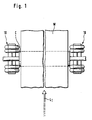
- a paper machine line is depicted, viewed from above.
- the direction of travel of the web W has been indicated with arrows L1.
- the guide of the invention has been disposed on both ends of the guide roll C of the paper web W.
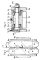
- the guide 10 of the invention comprises, as shown in Fig. 2, a bearing housing 11 for the web guide roll.
- the bearing housing 11 comprises a bearing housing cover 12, which is detachably connectable to the frame of the bearing housing, advantageously with screw means (not depicted).
- a centric bearing space 14 of the bearing housing in which can be mounted the bearing, advantageously a spherical bearing, for the end journal of the guide roll.
- the guide of the invention comprises bellows on either side of the vertical central axis Y of the guide 10: a first bellows 17 and a second bellows 18.
- the guide 10 comprises, within the bearing housing 13, first bellows fixing means 15, for the first bellows 17, and second bellows fixing means 16 for the second bellows 18.
- the first bellows 17 is a unitary component, structurally comprising a first bellows section 17a and a second bellows section 17b.
- the second bellows on the other side of the central axis Y of the guide 10, comprises the first bellows section 18a and the second bellows section 18b of the second bellows 18.
- the bellows 17 and 18 consist advantageously of a resilient, elastic material.
- the first bellows 17 comprises, bounding on the resilient bellows section, and fixing the bellows section, a first fixing flange 19a1 and a second fixing flange 19a2.
- the first fixing flange 19a1 attaches to the bellows section 17a
- the second fixing flange 19a2 attaches to the bellows section 17b.
- the second bellows 18 comprises a first fixing flange 20a1, which attaches to the bellows section 18a, and a second fixing flange 20a2, which attaches to the bellows section 18b.
- a smaller diameter fixing member 19b1 Associated with the flange 19a2 is a smaller diameter fixing member 19b1, which further attaches to the vertical frame section 21b of the frame 21, e.g. by screw means (not depicted).
- the fixing flange 19a2 comprises, associated with it, a smaller diameter fixing member 19b2, which is further detachably attachable to the frame 13 of the bearing housing, to its fixing section 15, advantageously likewise with similar screw means.
- Similar fixing members 20b1 and 20b2 are provided on the bellows component 18 for attaching the bellows 18 both to the bearing housing, to its frame 13, and to the vertical frame section 21c of the fixed frame 21.
- the first bellows 17 as well as the second bellows 18 have similar structural parts, and the bellows 17 and 18 are detachable for the duration of maintenance work from the frame section 13 and from the vertical frame section 21b and 21c of the fixed frame section 21. Therefore the bellows 17 and 18 together with the bearing means therein can be detached as a unit for the duration of maintenance work and replacement bellows can immediately be installed in their place, whereby web shut-downs are avoided.
- bellows 17 and 18 have equivalent structural components. As a result there are few different frame components, whereby the production costs will be lower.
- the guide 10 comprises a fixed frame 21, which comprises a horizontal frame section 21a and vertical frame sections 21b and 21c.
- the first bellows 17 attaches to the first vertical frame section 21b and the second bellows 18, to the second vertical frame section 21c.
- the first bellows 17 comprises a fluid space 31 therewithin, into which a pressurized fluid can be introduced for moving the bearing housing 11 horizontally.
- the second bearing housing 18 similarly comprises a fluid space 32, into which pressurized fluid, or vacuum, can be introduced for moving the bearing housing 11 in desired direction.
- the fluid pressure advantageously that of compressed air or of a hydraulic liquid, can be introduced into the pressurized fluid spaces 31 and/or 32 either of one bellows, 17 or 18, or of both bellows 17 and 18.
- the guide 10 comprises a first position measuring means 32, consisting substantially, as depicted in Fig. 2, of a horizontal rod component 23 which has been turnably pivoted with a bearing 24 to the frame 13 of the bearing housing 11.
- the position measuring means 22 further comprises a second rod 26, pivoted with the aid of a bearing 25 to the horizontal rod component 23.
- the vertical rod 26 is further connected to an angular position measuring means 27, this being for instance a potentiometer, which indicates the angular position of the rod 26 and, by this means, the position in horizontal direction of the bearing housing 11.
- the position information concerning the bearing housing can in this way be further transmitted to guide position remote control apparatus.
- the guide 10 further comprises a second detector means 28 registering the position of the bearing housing 11, consisting of a position pointer 29 fixed on the fixed frame 21 and of a scale 30 mounted on the frame 13 of the bearing housing 11 and moving along with the frame 13. At the pointer 29, the position of the bearing housing 11 is readable on the scale 30.
- first bellows 17 and the second bellows 18 are provided suspension means for the bearing housing 11, and they are equivalent as to their structural components in both bellows 17 and 18.
- the first bellows 17 contains a first bearing lug 33, located inside the first bellows 17, in its pressurized fluid space 31, this lug further attaching fixedly to the flange 19a1.
- a guide arm 37 has been placed within the pressurized fluid space 31, this arm connecting at one end with the pivot point of the first bearing lug 33, i.e., with the bearing 34, and at the other end with the pivot point 35 of the second bearing lug which is fixedly attached to the second flange 19a2, i.e., with the bearing 36.
- the arm 37 is thus turnably pivoted at both ends relative to the lugs 33 and 35.
- the second bellows 18 similarly contains equivalent structural components.
- a first lug 38 fixedly connected to the flange 20a2 and a second lug 40, fixedly connected to the flange 20a1.
- the first lug 38 comprises a pivot point, or bearing point, 39 for turnably pivoting the arm 42
- the second bearing lug 40 comprises a pivot point, or bearing point, 41 for turnably pivoting the other end of the arm 42.
- the pivot point 34 of the first lug 33 of the first bellows 17 is located above the longitudinal central axis X of the apparatus, and the pivot point 36 of the second lug 35 is correspondingly located below the central axis X.
- the pivot point 39 of the first lug 38 of the second bellows 18 is located above the central axis X, and the pivot point 41 of the second lug 40 is correspondingly located below the central axis X. Therefore, as depicted in Fig.
- the first bellows 17 is disposed in such position that the fixed lug 33 with its pivot point 34 lies below the central axis X and correspondingly the movable lug 35 with its movable pivot point 36 lies above the central axis X, that is if the bellows 17 is inverted, and if the apparatus arrangement regarding the bellows 18 is otherwise as in Fig. 2, the horizontal displacement of the roll centre will follow a convex path.
- the centre-point of the journal pin is positioned at the topmost point of the convex path, and then position of the journal pin centre descends on movement of the bearing housing 11 in either direction from the centre position.
- Fig. 4 is depicted the bellows design of Fig. 2, on larger scale.
- the figure shows the first bellows 17.
- the structural design is fully identical for the bellows 18, except that the location of the pivot points may be different depending on the position of the bellows, as has been described above.
- the entire bellows structure 17 is detachable as a unit for maintenance work, and the bellows structure 17 comprises a first bellows section 17a and a second bellows section 17b.
- a pressurized fluid space 31 Inside the bellows is provided a pressurized fluid space 31, into which pressurized fluid can be introduced through either or both flanges 19a1 and/or 19a2.
- With the first bellows section 17a connects the flange 19a1. It is further connected with the fixing component 19b1.
- the other half of the bellows is similar in construction. It comprises the bellows section 17b2, which connects with the flange 19a2.
- the flange 19a2 further comprises the fixing component 19b1.
- the bellows structure is enabled to be turned, in accordance with the intended use, so that the position relative to each other of the pivot points 36 and 34 can be changed with reference to the central axis X.
- To the flange 19a1 attaches fixedly a first bearing lug 33, comprising a pivot 34.
- To the flange 19a2 attaches fixedly a second bearing lug 35, which comprises the pivot 36.
- the bellows structure 17a, 17b proper, surrounding the pressurized fluid space 31, consists of elastic, yielding material, advantageously of continuous material.
- the arm 37 comprises the arm section 37a proper and a sleeve part 37b on its end.
- the arm 37 has been placed between the first lug half 33a and second lug half of the lug 33.
- the pivot 34 comprises a bearing axle 34a having at one end an axle section 34c, which comprises threads 34c1, and at the other end is provided an axle section 34b, which comprises a cotter pin hole 34b1.
- the axle (34a, 34b, 34c) has been carried through the lug sections 33a and 33b and fixed with a cotter pin 34g relative to said lug portions.
- a nut 34d has been screwed on the thread 34c1 of the axle.
- bearing means 34e1 and 34e2 are advantageously conical roller bearings, whereby accurate and play-free rotation is obtained.
- the arm 37 turns relative to the axle 34a, carried by the bearings 34e1 and 34e2.
- the sleeve part 37b of the arm 37 furthermore carries a grease nipple 34f, through which said bearing means 34e1 and 34e2 can be provided with lubricant.
Landscapes
- Support Of The Bearing (AREA)
- Rolls And Other Rotary Bodies (AREA)
- Folding Of Thin Sheet-Like Materials, Special Discharging Devices, And Others (AREA)
- Registering, Tensioning, Guiding Webs, And Rollers Therefor (AREA)
- Advancing Webs (AREA)
- Pressure Welding/Diffusion-Bonding (AREA)
- Lubricants (AREA)
- Meat, Egg Or Seafood Products (AREA)
- Paper (AREA)
- Train Traffic Observation, Control, And Security (AREA)
Claims (5)
Priority Applications (1)
| Application Number | Priority Date | Filing Date | Title |
|---|---|---|---|
| AT88850305T ATE70250T1 (de) | 1987-09-18 | 1988-09-16 | Justierbare fuehrung fuer bewegte bahnen oder stoffbahnen. |
Applications Claiming Priority (2)
| Application Number | Priority Date | Filing Date | Title |
|---|---|---|---|
| FI874092A FI77434C (fi) | 1987-09-18 | 1987-09-18 | Reglerbart styrorgan foer roerliga banor eller vaevnader. |
| FI874092 | 1987-09-18 |
Publications (3)
| Publication Number | Publication Date |
|---|---|
| EP0308385A2 EP0308385A2 (de) | 1989-03-22 |
| EP0308385A3 EP0308385A3 (en) | 1989-05-24 |
| EP0308385B1 true EP0308385B1 (de) | 1991-12-11 |
Family
ID=8525086
Family Applications (1)
| Application Number | Title | Priority Date | Filing Date |
|---|---|---|---|
| EP88850305A Expired - Lifetime EP0308385B1 (de) | 1987-09-18 | 1988-09-16 | Justierbare Führung für bewegte Bahnen oder Stoffbahnen |
Country Status (5)
| Country | Link |
|---|---|
| US (1) | US4932578A (de) |
| EP (1) | EP0308385B1 (de) |
| AT (1) | ATE70250T1 (de) |
| DE (1) | DE3866840D1 (de) |
| FI (1) | FI77434C (de) |
Families Citing this family (3)
| Publication number | Priority date | Publication date | Assignee | Title |
|---|---|---|---|---|
| FI94781C (fi) * | 1993-01-29 | 1995-10-25 | Valmet Paper Machinery Inc | Paperikoneen kudoksen ohjainlaite |
| US6371347B1 (en) | 1999-03-09 | 2002-04-16 | Ronald Melvin Gilbertson | Air switch and palm guide for papermaking machinery |
| NO312847B1 (no) * | 2001-01-29 | 2002-07-08 | Voith Paper Patent Gmbh | Forbedret regulerbart lager for sidestyring av löpende baner, samt fremgangsmåte for utskifting av slitasjedeler i dette |
Family Cites Families (9)
| Publication number | Priority date | Publication date | Assignee | Title |
|---|---|---|---|---|
| BE549133A (de) * | ||||
| US3101005A (en) * | 1960-03-26 | 1963-08-20 | Voith Gmbh J M | Belt-aligning structure |
| US3107036A (en) * | 1961-09-14 | 1963-10-15 | Ind Ovens Inc | Self-adjusting web guiding apparatus |
| US3750920A (en) * | 1971-04-05 | 1973-08-07 | Gilbert & Nash Co Inc | Web guide |
| US3841722A (en) * | 1972-03-16 | 1974-10-15 | Tampella Oy Ab | Automatic guide for roll |
| US3966106A (en) * | 1974-07-24 | 1976-06-29 | Dominion Engineering Works, Limited | Follower roll suspension system |
| US4666073A (en) * | 1984-07-25 | 1987-05-19 | Dufour Kenneth S | Spring biased spool type valve controller for a pneumatic dual diaphragm control system |
| US4610739A (en) * | 1984-11-02 | 1986-09-09 | Adolph Coors Company | Method and device for providing longitudinal and lateral stretch control in laminated webs |
| DE3540881A1 (de) * | 1985-11-18 | 1987-06-04 | Windmoeller & Hoelscher | Vorrichtung zum steuern der lage von bahnen oder foerderbaendern relativ zu deren leit- oder umlenkwalzen |
-
1987
- 1987-09-18 FI FI874092A patent/FI77434C/fi not_active IP Right Cessation
-
1988
- 1988-09-14 US US07/244,501 patent/US4932578A/en not_active Expired - Lifetime
- 1988-09-16 AT AT88850305T patent/ATE70250T1/de not_active IP Right Cessation
- 1988-09-16 DE DE8888850305T patent/DE3866840D1/de not_active Expired - Lifetime
- 1988-09-16 EP EP88850305A patent/EP0308385B1/de not_active Expired - Lifetime
Also Published As
| Publication number | Publication date |
|---|---|
| FI874092A0 (fi) | 1987-09-18 |
| US4932578A (en) | 1990-06-12 |
| EP0308385A3 (en) | 1989-05-24 |
| FI77434C (fi) | 1989-03-10 |
| DE3866840D1 (de) | 1992-01-23 |
| ATE70250T1 (de) | 1991-12-15 |
| EP0308385A2 (de) | 1989-03-22 |
| FI77434B (fi) | 1988-11-30 |
Similar Documents
| Publication | Publication Date | Title |
|---|---|---|
| US3639993A (en) | Improvements relating to machines and apparatus having a support for guiding a movable member | |
| US4684088A (en) | Support apparatus for an optical observation device | |
| US5971404A (en) | Self-centering suspension for in-pipe use | |
| FI94067C (fi) | Kalanteri | |
| CA1279507C (en) | Setting device for adjusting the position of a roll | |
| US4741607A (en) | Supporting device for an optical observation instrument | |
| US5906305A (en) | Apparatus for the corrective positioning of a travelling web at right angles to the direction of travel | |
| EP0308385B1 (de) | Justierbare Führung für bewegte Bahnen oder Stoffbahnen | |
| US4659278A (en) | Manipulator based on the pantograph principle | |
| KR100294385B1 (ko) | 수직형 지지 엑튜에이터를 구비한 철도 차량 | |
| EP0864063B1 (de) | Mikroskopstativ, insbesondere für ein Operationsmikroskop | |
| US4516491A (en) | Roll cross-axis mechanism | |
| EP0060483A1 (de) | Handhabungsroboter | |
| US4909450A (en) | Roller mill | |
| DE4032332C2 (de) | Meßeinrichtung zur Erfassung des Pendelwinkels | |
| US6547932B1 (en) | Doctor equipment in connection with a roll/cylinder in a paper/board machine | |
| US4966653A (en) | Apparatus for controlling a moving band | |
| US6627044B2 (en) | Web guide in a paper machine/board machine | |
| US4872617A (en) | Canted, spring-loaded feed screw support | |
| US2112293A (en) | Individual wheel spring suspension | |
| US5034101A (en) | Headbox with support beam on movable duct wall | |
| US4587742A (en) | Scale balancing device in universal parallel ruler device | |
| CN213629647U (zh) | 位置调整装置及底盘装置 | |
| CN2276394Y (zh) | 轧辊数控磨床测量臂臂杆安装结构 | |
| CA2061322C (en) | Headbox for a papermaking machine |
Legal Events
| Date | Code | Title | Description |
|---|---|---|---|
| PUAI | Public reference made under article 153(3) epc to a published international application that has entered the european phase |
Free format text: ORIGINAL CODE: 0009012 |
|
| AK | Designated contracting states |
Kind code of ref document: A2 Designated state(s): AT CH DE ES FR GB IT LI SE |
|
| PUAL | Search report despatched |
Free format text: ORIGINAL CODE: 0009013 |
|
| AK | Designated contracting states |
Kind code of ref document: A3 Designated state(s): AT CH DE ES FR GB IT LI SE |
|
| 17P | Request for examination filed |
Effective date: 19890703 |
|
| 17Q | First examination report despatched |
Effective date: 19901214 |
|
| GRAA | (expected) grant |
Free format text: ORIGINAL CODE: 0009210 |
|
| AK | Designated contracting states |
Kind code of ref document: B1 Designated state(s): AT CH DE ES FR GB IT LI SE |
|
| PG25 | Lapsed in a contracting state [announced via postgrant information from national office to epo] |
Ref country code: IT Free format text: LAPSE BECAUSE OF FAILURE TO SUBMIT A TRANSLATION OF THE DESCRIPTION OR TO PAY THE FEE WITHIN THE PRESCRIBED TIME-LIMIT;WARNING: LAPSES OF ITALIAN PATENTS WITH EFFECTIVE DATE BEFORE 2007 MAY HAVE OCCURRED AT ANY TIME BEFORE 2007. THE CORRECT EFFECTIVE DATE MAY BE DIFFERENT FROM THE ONE RECORDED. Effective date: 19911211 Ref country code: LI Effective date: 19911211 Ref country code: ES Free format text: THE PATENT HAS BEEN ANNULLED BY A DECISION OF A NATIONAL AUTHORITY Effective date: 19911211 Ref country code: FR Effective date: 19911211 Ref country code: CH Effective date: 19911211 |
|
| REF | Corresponds to: |
Ref document number: 70250 Country of ref document: AT Date of ref document: 19911215 Kind code of ref document: T |
|
| REF | Corresponds to: |
Ref document number: 3866840 Country of ref document: DE Date of ref document: 19920123 |
|
| REG | Reference to a national code |
Ref country code: CH Ref legal event code: PL |
|
| EN | Fr: translation not filed | ||
| PG25 | Lapsed in a contracting state [announced via postgrant information from national office to epo] |
Ref country code: GB Effective date: 19920916 Ref country code: AT Effective date: 19920916 |
|
| PG25 | Lapsed in a contracting state [announced via postgrant information from national office to epo] |
Ref country code: SE Effective date: 19920917 |
|
| PLBE | No opposition filed within time limit |
Free format text: ORIGINAL CODE: 0009261 |
|
| STAA | Information on the status of an ep patent application or granted ep patent |
Free format text: STATUS: NO OPPOSITION FILED WITHIN TIME LIMIT |
|
| 26N | No opposition filed | ||
| GBPC | Gb: european patent ceased through non-payment of renewal fee |
Effective date: 19920916 |
|
| PG25 | Lapsed in a contracting state [announced via postgrant information from national office to epo] |
Ref country code: DE Effective date: 19930602 |
|
| EUG | Se: european patent has lapsed |
Ref document number: 88850305.9 Effective date: 19930406 |