EP0308230A2 - Extraction device - Google Patents
Extraction device Download PDFInfo
- Publication number
- EP0308230A2 EP0308230A2 EP88308557A EP88308557A EP0308230A2 EP 0308230 A2 EP0308230 A2 EP 0308230A2 EP 88308557 A EP88308557 A EP 88308557A EP 88308557 A EP88308557 A EP 88308557A EP 0308230 A2 EP0308230 A2 EP 0308230A2
- Authority
- EP
- European Patent Office
- Prior art keywords
- notch
- swab
- cavity
- container
- pipette
- Prior art date
- Legal status (The legal status is an assumption and is not a legal conclusion. Google has not performed a legal analysis and makes no representation as to the accuracy of the status listed.)
- Ceased
Links
Images


Classifications
-
- A—HUMAN NECESSITIES
- A61—MEDICAL OR VETERINARY SCIENCE; HYGIENE
- A61B—DIAGNOSIS; SURGERY; IDENTIFICATION
- A61B10/00—Other methods or instruments for diagnosis, e.g. instruments for taking a cell sample, for biopsy, for vaccination diagnosis; Sex determination; Ovulation-period determination; Throat striking implements
- A61B10/0096—Casings for storing test samples
Definitions
- This invention relates to a device used for extracting biological material from a swab, for example, cells from a throat specimen.
- test tubes used have not been conducive to the use of a minimum of extracting fluid.
- biological material of choice has been substantially diluted. This results from the generally large volume of the test tube and the construction of such a container for delivery of the resultant extracted material by pouring off. In addition, little is provided in the test tube to encourage total extraction of the biological material, or the fluid, from the swab.
- This device comprises a container having an internal surface defining a major cavity for confining an extracting liquid medium, and means in the container defining a notch extending into a portion of the internal surface, the notch being configured to receive a swab-like collector and to hold such a collector in the major cavity, the notch having one end that is deeper within the cavity than the rest of the notch, the end being configured to hold the absorbent end of such a collector, and centering means in the container for centering a pipette for aspiration of such extracting medium, the centering means being disposed generally about a line that intersects the notch at a point generally adjacent the one end.
- an extraction device that extracts the maximum amount of biological material from a swab using a limited amount of extracting medium
- the device of the invention is described in connection with the preferred embodiments, wherein a swab is used as the collecting means for collecting specimen from a patient, and extracted material is aspirated by a pipette.
- the device of the invention is useful with other similar collectors, such as a dip stick having absorbent pads at one end thereof. It is also useful with aspirators besides pipettes.
- the invention is to the extracting device, rather than to any particular form of collecting means used to place the specimen into the device for extraction, or to a particular aspirator used to remove the liquid used in the extraction.
- top refers to portions of the device as it is oriented in its position of use.
- an extraction device constructed in accord with the invention comprises a container 10 having supporting legs 12, 14 and 16, Figure 1.
- the container has a top surface 18.
- a major cavity 20 is molded into the container, as formed by internal surface 22.
- Cavity 20 provides the confinement of the extracting liquid medium, and is shaped with a deep end 24, Figure 3, that is generally at an end of container 10 opposite to the leg 14 and provides an additional leg of support.
- the bottom extent of cavity 20 is indicated by surface 26, Figure 3.
- Top surface 18 limits the extent of cavity 20 and its contents.
- cavity 20 slopes downwardly, generally right to left, as measured at its bottom surface 26.
- the volume of cavity 20 is variable, depending on how large is container 10. Most preferably, however, that volume is kept small reduce the dilution effect.
- a useful example of such volume of cavity 20 by itself, is about 0.8 ml.
- Notch 30 has a bottom surface 32 that is inclined at an angle ⁇ with respect to top surface 18. Angle ⁇ can vary generally from about 2° to about 60°, and most preferably is about 16°.
- Notch 30 and bottom surface 32 thereof are an extension of cavity 20, since both are formed by the same molded, internal surface 22.
- notch 30 contributes to the volume of cavity 20, for example, about 0.2 ml.
- the total volume of cavity 20 and notch 30 is about 1.01 ml.
- surface 22 is optionally provided with protruding lips 40, 42 adjacent top surface 18, on each side of the notch.
- the distance d, Figure 2, between lips 40, 42 is such that a swab can be snapped into notch 30, and then forcibly pulled therefrom.
- "d" can be about 1.5 mm.
- centering surface 50 is provided in internal surface 22, adjacent deep end 24.
- Such centering surface is shaped with an internal radius r1 at top surface 18 that is larger than the internal radius r2 located further into cavity 20.
- the orientation of surface 50 is generally vertical, that is, about an axis 56 that extends at an angle ⁇ to top surface 18. Most preferably, ⁇ is generally about 90°.
- Axis 56 is also the centering line for insertion of pipette P into the device to aspirate up the liquid medium used for extraction.
- surface 50 is shaped to generally center and support the pipette P for aspiration of the extracting liquid.
- a swab is disposed within notch 30 with the absorbent end at deep end 24 of cavity 20.
- An appropriate extracting medium is poured into cavity 20, and allowed to act on the swab.
- Such liquids are conventional and need no further description.
- swab S is reciprocated and rotated along notch 30, towards and away from deep end 24, as a means for agitating the extracting liquid and to encourage the extraction of the biological material.
- a pipette P of any suitable construction is inserted along axis 56 down on top of the absorbent end of the swab (shown in phantom, Figure 3).
- the angle between the positioning of swab S and the positioning of pipette P an axis 56 is ( ⁇ - ⁇ ).
- container 10a has a cavity 20a generally constructed as in the previous embodiment, with an internal surface 22a and a deep end 24a, Figure 5.
- notch 30a for swab S instead of extending below cavity 20a, is provided in a portion 100 rising vertically above the limiting surface 18a that defines the top of cavity 20a.
- notch 30a extends at an angle ⁇ ′ to surface 18a that is generally 90°. Notch 30a is also preferably enlarged at deep end 24a, to accommodate the absorbent end of the swab. Lips 40a and 42a are provided as in the previous embodiment.
- centering surface 50a that extends below the bottom surface 26a of cavity 20a, Figure 5. That surface provides a centering axis 56a that is inclined to surface 18a at an angle ⁇ ′, which has a value between about 2° and 60°, and preferably about 16°. Centering surface 50a preferably terminates at a stop 110 that locates the aperture of pipette P adjacent swab S, Figure 6.
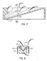
- Antisplash features are optionally included in internal surface 22, as shown in Figures 7 and 8. Parts similar to those previously described bear the same reference numeral to which the distinguishing suffix "b" is added.
- container 10b has a cavity 20b, notch 30b, and centering surface 50b, all substantially identical to that described in the embodiment of Figures 1-3.
- internal surface 22b has been folded outwardly at 200 to provide two grooves, each on opposite sides of notch 30. These grooves act to damp out any splashing that might occur when swab S is pushed back and forth along notch 30b. Most preferably they extend generally parallel to bottom surface 26b of cavity 20b.
- Useful materials for the device of the invention include molded plastics material, for example, polyethylene, polypropylene and the like.
Abstract
a container (10) having an internal surface defining a major cavity (20) for confining an extracting liquid medium, and
means in said container defining a notch (30) extending into a portion of said internal surface, said notch being configured to receive a swab-like collector and to hold such a collector in said major cavity, said notch having one end (24) that is deeper within said cavity than the rest of said notch, said end being configured to hold the absorbent end of such a collector,
and centering means (50) in said container for centering a pipette (P) for aspiration of such extracting medium, said centering means being disposed generally about a line (56) that intersects said notch at a point generally adjacent said one end.
Description
- This invention relates to a device used for extracting biological material from a swab, for example, cells from a throat specimen.
- It is common practice to obtain a biological specimen from a patient via a swab, and then to extract the particular biological material of choice from the swab. The extraction step uses a liquid particularly adapted for the extraction, based upon the choice of solvent and the optional addition of enzymes. Frequently the extraction takes place in a test tube, followed by a suitable transfer of the extracting liquid to a sample plate for analysis. Examples of such a procedure appear in U.S. Patent No. 4,618,576.
- The procedure described has been less than completely satisfactory because the test tubes used have not been conducive to the use of a minimum of extracting fluid. As a result, the biological material of choice has been substantially diluted. This results from the generally large volume of the test tube and the construction of such a container for delivery of the resultant extracted material by pouring off. In addition, little is provided in the test tube to encourage total extraction of the biological material, or the fluid, from the swab.
- There has been, therefore, prior to this invention, an unsolved problem of a container to be used with a swab in the extracting step that minimizes the above-noted disadvantages.
- The above problem is addressed by a device for extracting biological materials from a swab-like collector using a pipette. This device comprises a container having an internal surface defining a major cavity for confining an extracting liquid medium, and
means in the container defining a notch extending into a portion of the internal surface, the notch being configured to receive a swab-like collector and to hold such a collector in the major cavity, the notch having one end that is deeper within the cavity than the rest of the notch, the end being configured to hold the absorbent end of such a collector,
and centering means in the container for centering a pipette for aspiration of such extracting medium, the centering means being disposed generally about a line that intersects the notch at a point generally adjacent the one end. - Thus, it is an advantageous feature of the invention that an extraction device is provided that extracts the maximum amount of biological material from a swab using a limited amount of extracting medium,
- It is a related advantageous feature of the invention that such a device is provided which allows the effective use of a pipette to remove the extracted biological material.
- The present invention will now be described by way of example with reference to the accompanying drawings in which:
- Figure 1 is an isometric view partially broken away, of a device constructed in accordance with the invention, showing a swab in place in the device;
- Figure 2 is a plan view of the device by itself;
- Figure 3 is a section view taken generally along the line III-III of Figure 2, and showing portions of the swab and a pipette in phantom;
- Figure 4 is a plan view similar to that of Figure 2, but illustrating an alternate embodiment;
- Figure 5 is a section view taken along line V-V of Figure 4;
- Figure 6 is an enlarged, fragmentary, section view taken of a portion of the device of Figure 5, on the same section line, illustrating in greater detail the use of the device of Figure 4;
- Figure 7 is a section view similar to that of Figure 3, except it illustrates yet another embodiment; and
- Figure 8 is a section view taken generally along the line VIII-VIII of Figure 7.
- The device of the invention is described in connection with the preferred embodiments, wherein a swab is used as the collecting means for collecting specimen from a patient, and extracted material is aspirated by a pipette. In addition, the device of the invention is useful with other similar collectors, such as a dip stick having absorbent pads at one end thereof. It is also useful with aspirators besides pipettes. Thus, the invention is to the extracting device, rather than to any particular form of collecting means used to place the specimen into the device for extraction, or to a particular aspirator used to remove the liquid used in the extraction.
- Terms such as "top", "vertical", "above" and the like refer to portions of the device as it is oriented in its position of use.
- Thus, referring to Figures 1-3, an extraction device constructed in accord with the invention comprises a
container 10 having supportinglegs top surface 18. Amajor cavity 20 is molded into the container, as formed byinternal surface 22.Cavity 20 provides the confinement of the extracting liquid medium, and is shaped with adeep end 24, Figure 3, that is generally at an end ofcontainer 10 opposite to the leg 14 and provides an additional leg of support. The bottom extent ofcavity 20 is indicated bysurface 26, Figure 3.Top surface 18 limits the extent ofcavity 20 and its contents. Thus,cavity 20 slopes downwardly, generally right to left, as measured at itsbottom surface 26. The volume ofcavity 20 is variable, depending on how large iscontainer 10. Most preferably, however, that volume is kept small reduce the dilution effect. A useful example of such volume ofcavity 20 by itself, is about 0.8 ml. - To hold a swab (S, shown in phantom, Figure 3) in proper position within
cavity 20,internal surface 22 is provided with anotch 30, which extends below thebottom surface 26 ofcavity 20.Notch 30 has abottom surface 32 that is inclined at an angle α with respect totop surface 18. Angle α can vary generally from about 2° to about 60°, and most preferably is about 16°. -
Notch 30 andbottom surface 32 thereof are an extension ofcavity 20, since both are formed by the same molded,internal surface 22. Thus,notch 30 contributes to the volume ofcavity 20, for example, about 0.2 ml. Thus the total volume ofcavity 20 andnotch 30 is about 1.01 ml. - To temporarily retain the swab in position in
notch 30,surface 22 is optionally provided with protrudinglips top surface 18, on each side of the notch. The distance d, Figure 2, betweenlips notch 30, and then forcibly pulled therefrom. For example, "d" can be about 1.5 mm. - To properly center a pipette P, shown in phantom, Figure 3,
centering surface 50 is provided ininternal surface 22, adjacentdeep end 24. Such centering surface is shaped with an internal radius r₁ attop surface 18 that is larger than the internal radius r₂ located further intocavity 20. The orientation ofsurface 50 is generally vertical, that is, about anaxis 56 that extends at an angle β totop surface 18. Most preferably, β is generally about 90°.Axis 56 is also the centering line for insertion of pipette P into the device to aspirate up the liquid medium used for extraction. - Therefore,
surface 50 is shaped to generally center and support the pipette P for aspiration of the extracting liquid. - The use of the device will be readily apparent from the preceding description. That is, a swab is disposed within
notch 30 with the absorbent end atdeep end 24 ofcavity 20. An appropriate extracting medium is poured intocavity 20, and allowed to act on the swab. Such liquids are conventional and need no further description. Optionally, swab S is reciprocated and rotated alongnotch 30, towards and away fromdeep end 24, as a means for agitating the extracting liquid and to encourage the extraction of the biological material. After an appropriate length of time, for example, 1 to 10 min., a pipette P of any suitable construction is inserted alongaxis 56 down on top of the absorbent end of the swab (shown in phantom, Figure 3). In this position, most of the extracting medium can be sucked into the pipette. Furthermore, because the pipette is aligned with the absorbent end of the swab, the suction action by the pipette acts to pull off any biological material tending to remain behind on the absorbent material. - The angle between the positioning of swab S and the positioning of pipette P an
axis 56 is (β-α). - It is not necessary, however, that the angle (β-α) be achieved only by orienting the pipette vertically. That is, the positions of the swab S and pipette P can be reversed, as shown in Figures 4-6. Parts similar to those previously described bear the same reference numeral, to which the distinguishing suffix "a" has been appended. Thus,
container 10a has a cavity 20a generally constructed as in the previous embodiment, with aninternal surface 22a and a deep end 24a, Figure 5. However,notch 30a for swab S, instead of extending below cavity 20a, is provided in aportion 100 rising vertically above the limitingsurface 18a that defines the top of cavity 20a. Thus,notch 30a extends at an angle α′ tosurface 18a that is generally 90°.Notch 30a is also preferably enlarged at deep end 24a, to accommodate the absorbent end of the swab.Lips - To center pipette P, shown in phantom,
surface 22a is provided with a centeringsurface 50a that extends below the bottom surface 26a of cavity 20a, Figure 5. That surface provides a centering axis 56a that is inclined to surface 18a at an angle β′, which has a value between about 2° and 60°, and preferably about 16°. Centeringsurface 50a preferably terminates at astop 110 that locates the aperture of pipette P adjacent swab S, Figure 6. - Antisplash features are optionally included in
internal surface 22, as shown in Figures 7 and 8. Parts similar to those previously described bear the same reference numeral to which the distinguishing suffix "b" is added. Thus,container 10b has acavity 20b,notch 30b, and centeringsurface 50b, all substantially identical to that described in the embodiment of Figures 1-3. In addition, however,internal surface 22b has been folded outwardly at 200 to provide two grooves, each on opposite sides ofnotch 30. These grooves act to damp out any splashing that might occur when swab S is pushed back and forth alongnotch 30b. Most preferably they extend generally parallel tobottom surface 26b ofcavity 20b. - Useful materials for the device of the invention include molded plastics material, for example, polyethylene, polypropylene and the like.
Claims (8)
a container having an internal surface defining a major cavity for confining an extracting liquid medium, and
means in said container defining a notch extending into a portion of said internal surface, said notch being configured to receive a swab-like collector and to hold such a collector in said major cavity, said notch having one end that is deeper within said cavity than the rest of said notch, said end being configured to hold the absorbent end of such a collector,
and centering means in said container for centering a pipette for aspiration of such extracting medium, said centering means being disposed generally about a line that intersects said notch at a point generally adjacent said one end.
Applications Claiming Priority (2)
| Application Number | Priority Date | Filing Date | Title |
|---|---|---|---|
| US98247 | 1987-09-18 | ||
| US07/098,247 US4746614A (en) | 1987-09-18 | 1987-09-18 | Extraction device |
Publications (2)
| Publication Number | Publication Date |
|---|---|
| EP0308230A2 true EP0308230A2 (en) | 1989-03-22 |
| EP0308230A3 EP0308230A3 (en) | 1989-12-13 |
Family
ID=22268339
Family Applications (1)
| Application Number | Title | Priority Date | Filing Date |
|---|---|---|---|
| EP88308557A Ceased EP0308230A3 (en) | 1987-09-18 | 1988-09-16 | Extraction device |
Country Status (4)
| Country | Link |
|---|---|
| US (1) | US4746614A (en) |
| EP (1) | EP0308230A3 (en) |
| JP (1) | JPH01120276A (en) |
| CA (1) | CA1319311C (en) |
Families Citing this family (15)
| Publication number | Priority date | Publication date | Assignee | Title |
|---|---|---|---|---|
| US4963325A (en) * | 1988-05-06 | 1990-10-16 | Hygeia Sciences, Inc. | Swab expressor immunoassay device |
| DE68922888T2 (en) * | 1988-10-07 | 1995-11-30 | Eastman Kodak Co | Use of a cationic surfactant to extract the main protein antigen of the outer membrane of Chlamydia. |
| US5075221A (en) * | 1988-10-07 | 1991-12-24 | Eastman Kodak Company | Stabilized extraction composition containing a sulfhydryl-containing reducing agent and its use in chlamydial and gonococcal determinations |
| US5132205A (en) * | 1988-10-07 | 1992-07-21 | Eastman Kodak Company | High ph extraction composition and its use to determine a chlamydial, gonococcal or herpes antigen |
| US5122449A (en) * | 1988-10-07 | 1992-06-16 | Eastman Kodak Company | Use of a protease in the extraction of chlamydial, gonococcal and herpes antigens |
| US5081010A (en) * | 1989-02-09 | 1992-01-14 | Eastman Kodak Company | Extraction composition, test kit and their use to extract or determine herpes simplex viral antigen |
| US5120503A (en) * | 1989-07-14 | 1992-06-09 | Eastman Kodak Company | Extracting device for extracting antigens |
| US5392909A (en) * | 1993-11-03 | 1995-02-28 | Linvatec Corporation | Releasable universal blister package for elongated surgical devices |
| US5660273A (en) * | 1994-07-13 | 1997-08-26 | Centrix, Inc. | Single patient dose medicament dispenser with applicator |
| US6328159B1 (en) | 1994-07-13 | 2001-12-11 | Centrix, Inc | Single patient dose medicament dispenser with applicator |
| US6685013B2 (en) | 1994-07-13 | 2004-02-03 | Centrix, Inc. | Single patient dose medicament dispenser with applicator |
| AU704070B2 (en) * | 1995-04-07 | 1999-04-15 | Linvatec Corporation | Package retainer for surgical screw |
| US6372816B1 (en) | 1999-06-25 | 2002-04-16 | Dentsply Detrey Gmbh | Dental materials packaging and method of use |
| US20050255425A1 (en) * | 2000-09-21 | 2005-11-17 | Pierson Paul R | Mixing tip for dental materials |
| JP5379061B2 (en) | 2010-03-31 | 2013-12-25 | 富士フイルム株式会社 | Extraction method and extraction container and extraction kit used therefor |
Citations (2)
| Publication number | Priority date | Publication date | Assignee | Title |
|---|---|---|---|---|
| EP0095630A1 (en) * | 1982-05-28 | 1983-12-07 | MERCK PATENT GmbH | Micro-organisms collection and transport device |
| FR2540513A1 (en) * | 1983-02-09 | 1984-08-10 | Schmorak Raymond | Device for preserving and transporting a bacterial sample |
Family Cites Families (5)
| Publication number | Priority date | Publication date | Assignee | Title |
|---|---|---|---|---|
| US3116828A (en) * | 1961-08-30 | 1964-01-07 | Jacob A Glassman | Surgical instrucment trays |
| US4014746A (en) * | 1973-05-08 | 1977-03-29 | U.S. Medical Research And Development, Inc. | Method of and apparatus for collecting cultures |
| US4014748A (en) * | 1975-12-22 | 1977-03-29 | Marion Laboratories, Inc. | Anaerobic culture collecting and transporting apparatus |
| US4153160A (en) * | 1978-01-30 | 1979-05-08 | Johannah Medical Services, Inc. | Disposable slide-step percutaneous transhepatic cholangiography procedure tray |
| US4618576A (en) * | 1984-02-27 | 1986-10-21 | Becton Dickinson And Company | Diagnostic test for Streptococcus A |
-
1987
- 1987-09-18 US US07/098,247 patent/US4746614A/en not_active Expired - Fee Related
-
1988
- 1988-04-06 CA CA000563371A patent/CA1319311C/en not_active Expired - Fee Related
- 1988-09-16 EP EP88308557A patent/EP0308230A3/en not_active Ceased
- 1988-09-16 JP JP63232141A patent/JPH01120276A/en active Pending
Patent Citations (2)
| Publication number | Priority date | Publication date | Assignee | Title |
|---|---|---|---|---|
| EP0095630A1 (en) * | 1982-05-28 | 1983-12-07 | MERCK PATENT GmbH | Micro-organisms collection and transport device |
| FR2540513A1 (en) * | 1983-02-09 | 1984-08-10 | Schmorak Raymond | Device for preserving and transporting a bacterial sample |
Also Published As
| Publication number | Publication date |
|---|---|
| JPH01120276A (en) | 1989-05-12 |
| EP0308230A3 (en) | 1989-12-13 |
| US4746614A (en) | 1988-05-24 |
| CA1319311C (en) | 1993-06-22 |
Similar Documents
| Publication | Publication Date | Title |
|---|---|---|
| EP0308230A2 (en) | Extraction device | |
| US4789639A (en) | Liquid recovery device | |
| US5915583A (en) | Container | |
| US5000193A (en) | Medical swab device | |
| EP1284160B1 (en) | Liquid specimen collection system | |
| JP2536946B2 (en) | Liquid control nozzle structure for liquid distribution | |
| EP1877771B1 (en) | Tumor screening system | |
| JPH05133854A (en) | Gravity aiding type collecting apparatus | |
| US4528187A (en) | Apparatus for collecting and microscopically examining a specimen | |
| CA2124705C (en) | Liquid specimen collector with removable extraction device | |
| WO1984000418A1 (en) | Container for small quantities of liquids | |
| DE69829531T2 (en) | Removal vasculature | |
| JPH0867B2 (en) | Inoculator and assembly | |
| US20180238778A1 (en) | Apparatus for spreading a fluid across a substrate and method of using the same | |
| EP0743095A1 (en) | Small volume disposable pipette tip | |
| US9339013B1 (en) | Urine collection device | |
| Columbus et al. | The integrated blood-collection system as a vehicle into complete clinical laboratory automation | |
| EP0084557A1 (en) | Container for small quantities of liquids | |
| JPH01169364A (en) | Pipette tip | |
| US20210394191A1 (en) | Universal stand for holding capillary and transfer pipettes | |
| CN215651250U (en) | Urine cup | |
| KR200302951Y1 (en) | Pipette for long type yellow tip | |
| US20220008911A1 (en) | Devices for extracting a fluid sample from a closed chamber and methods of use thereof | |
| JP2538518B2 (en) | Centrifugal test tube for urine sediment | |
| JPH0663136U (en) | Test tube |
Legal Events
| Date | Code | Title | Description |
|---|---|---|---|
| PUAI | Public reference made under article 153(3) epc to a published international application that has entered the european phase |
Free format text: ORIGINAL CODE: 0009012 |
|
| AK | Designated contracting states |
Kind code of ref document: A2 Designated state(s): CH DE FR GB IT LI SE |
|
| PUAL | Search report despatched |
Free format text: ORIGINAL CODE: 0009013 |
|
| AK | Designated contracting states |
Kind code of ref document: A3 Designated state(s): CH DE FR GB IT LI SE |
|
| 17P | Request for examination filed |
Effective date: 19900116 |
|
| 17Q | First examination report despatched |
Effective date: 19920408 |
|
| STAA | Information on the status of an ep patent application or granted ep patent |
Free format text: STATUS: THE APPLICATION HAS BEEN REFUSED |
|
| 18R | Application refused |
Effective date: 19920927 |