EP0308191B1 - Isolierung mit einer an einem Klebeband haftenden Oberfläche - Google Patents
Isolierung mit einer an einem Klebeband haftenden Oberfläche Download PDFInfo
- Publication number
- EP0308191B1 EP0308191B1 EP88308483A EP88308483A EP0308191B1 EP 0308191 B1 EP0308191 B1 EP 0308191B1 EP 88308483 A EP88308483 A EP 88308483A EP 88308483 A EP88308483 A EP 88308483A EP 0308191 B1 EP0308191 B1 EP 0308191B1
- Authority
- EP
- European Patent Office
- Prior art keywords
- segment
- strip
- tape
- layer
- insulation
- Prior art date
- Legal status (The legal status is an assumption and is not a legal conclusion. Google has not performed a legal analysis and makes no representation as to the accuracy of the status listed.)
- Expired - Lifetime
Links
- 238000009413 insulation Methods 0.000 title claims abstract description 100
- 239000000853 adhesive Substances 0.000 claims abstract description 47
- 230000001070 adhesive effect Effects 0.000 claims abstract description 47
- 239000004820 Pressure-sensitive adhesive Substances 0.000 claims abstract description 34
- 239000012530 fluid Substances 0.000 claims abstract description 6
- 239000002390 adhesive tape Substances 0.000 claims abstract description 4
- 239000010410 layer Substances 0.000 claims description 146
- 239000000463 material Substances 0.000 claims description 76
- 239000011248 coating agent Substances 0.000 claims description 67
- 238000000576 coating method Methods 0.000 claims description 67
- 238000007789 sealing Methods 0.000 claims description 23
- 239000003054 catalyst Substances 0.000 claims description 21
- 239000002904 solvent Substances 0.000 claims description 16
- 229920000728 polyester Polymers 0.000 claims description 15
- 229920006395 saturated elastomer Polymers 0.000 claims description 14
- XLYOFNOQVPJJNP-UHFFFAOYSA-N water Substances O XLYOFNOQVPJJNP-UHFFFAOYSA-N 0.000 claims description 13
- 239000012790 adhesive layer Substances 0.000 claims description 11
- 229920001228 polyisocyanate Polymers 0.000 claims description 6
- 239000005056 polyisocyanate Substances 0.000 claims description 6
- 239000011810 insulating material Substances 0.000 claims 1
- 239000000123 paper Substances 0.000 description 82
- 239000011152 fibreglass Substances 0.000 description 27
- ZWEHNKRNPOVVGH-UHFFFAOYSA-N 2-Butanone Chemical compound CCC(C)=O ZWEHNKRNPOVVGH-UHFFFAOYSA-N 0.000 description 12
- 239000004800 polyvinyl chloride Substances 0.000 description 11
- YXFVVABEGXRONW-UHFFFAOYSA-N Toluene Chemical compound CC1=CC=CC=C1 YXFVVABEGXRONW-UHFFFAOYSA-N 0.000 description 9
- 230000032798 delamination Effects 0.000 description 9
- 229920000915 polyvinyl chloride Polymers 0.000 description 9
- 230000001921 mouthing effect Effects 0.000 description 8
- 241000251468 Actinopterygii Species 0.000 description 7
- 230000005484 gravity Effects 0.000 description 7
- 239000012939 laminating adhesive Substances 0.000 description 7
- 239000007787 solid Substances 0.000 description 7
- 239000000126 substance Substances 0.000 description 7
- YMWUJEATGCHHMB-UHFFFAOYSA-N Dichloromethane Chemical compound ClCCl YMWUJEATGCHHMB-UHFFFAOYSA-N 0.000 description 6
- 238000004026 adhesive bonding Methods 0.000 description 6
- DKPFZGUDAPQIHT-UHFFFAOYSA-N butyl acetate Chemical compound CCCCOC(C)=O DKPFZGUDAPQIHT-UHFFFAOYSA-N 0.000 description 6
- RNFJDJUURJAICM-UHFFFAOYSA-N 2,2,4,4,6,6-hexaphenoxy-1,3,5-triaza-2$l^{5},4$l^{5},6$l^{5}-triphosphacyclohexa-1,3,5-triene Chemical compound N=1P(OC=2C=CC=CC=2)(OC=2C=CC=CC=2)=NP(OC=2C=CC=CC=2)(OC=2C=CC=CC=2)=NP=1(OC=1C=CC=CC=1)OC1=CC=CC=C1 RNFJDJUURJAICM-UHFFFAOYSA-N 0.000 description 5
- -1 aliphatic isocyanate Chemical class 0.000 description 5
- 239000003063 flame retardant Substances 0.000 description 5
- 239000002655 kraft paper Substances 0.000 description 5
- 238000000034 method Methods 0.000 description 5
- 229910052782 aluminium Inorganic materials 0.000 description 4
- XAGFODPZIPBFFR-UHFFFAOYSA-N aluminium Chemical compound [Al] XAGFODPZIPBFFR-UHFFFAOYSA-N 0.000 description 4
- 238000009434 installation Methods 0.000 description 4
- 239000012948 isocyanate Substances 0.000 description 4
- 239000000203 mixture Substances 0.000 description 4
- 229920003023 plastic Polymers 0.000 description 4
- 239000004033 plastic Substances 0.000 description 4
- 229920000058 polyacrylate Polymers 0.000 description 4
- 239000011347 resin Substances 0.000 description 4
- 229920005989 resin Polymers 0.000 description 4
- DXPPIEDUBFUSEZ-UHFFFAOYSA-N 6-methylheptyl prop-2-enoate Chemical compound CC(C)CCCCCOC(=O)C=C DXPPIEDUBFUSEZ-UHFFFAOYSA-N 0.000 description 3
- CTQNGGLPUBDAKN-UHFFFAOYSA-N O-Xylene Chemical compound CC1=CC=CC=C1C CTQNGGLPUBDAKN-UHFFFAOYSA-N 0.000 description 3
- 238000010438 heat treatment Methods 0.000 description 3
- 229920006267 polyester film Polymers 0.000 description 3
- 230000003068 static effect Effects 0.000 description 3
- 239000008096 xylene Substances 0.000 description 3
- 238000010521 absorption reaction Methods 0.000 description 2
- NIXOWILDQLNWCW-UHFFFAOYSA-N acrylic acid group Chemical group C(C=C)(=O)O NIXOWILDQLNWCW-UHFFFAOYSA-N 0.000 description 2
- 238000010276 construction Methods 0.000 description 2
- 239000000428 dust Substances 0.000 description 2
- 239000011888 foil Substances 0.000 description 2
- 239000012456 homogeneous solution Substances 0.000 description 2
- 239000007788 liquid Substances 0.000 description 2
- 238000004519 manufacturing process Methods 0.000 description 2
- 229910052751 metal Inorganic materials 0.000 description 2
- 239000002184 metal Substances 0.000 description 2
- 239000011140 metalized polyester Substances 0.000 description 2
- 239000011490 mineral wool Substances 0.000 description 2
- 229920001225 polyester resin Polymers 0.000 description 2
- 239000004645 polyester resin Substances 0.000 description 2
- 239000007921 spray Substances 0.000 description 2
- 239000010902 straw Substances 0.000 description 2
- 210000002268 wool Anatomy 0.000 description 2
- RYGMFSIKBFXOCR-UHFFFAOYSA-N Copper Chemical compound [Cu] RYGMFSIKBFXOCR-UHFFFAOYSA-N 0.000 description 1
- JOYRKODLDBILNP-UHFFFAOYSA-N Ethyl urethane Chemical compound CCOC(N)=O JOYRKODLDBILNP-UHFFFAOYSA-N 0.000 description 1
- 229920002472 Starch Polymers 0.000 description 1
- 229910000831 Steel Inorganic materials 0.000 description 1
- 239000003522 acrylic cement Substances 0.000 description 1
- 230000004888 barrier function Effects 0.000 description 1
- OKHQYCPETODROI-UHFFFAOYSA-N butyl acetate;1,2-xylene Chemical group CCCCOC(C)=O.CC1=CC=CC=C1C OKHQYCPETODROI-UHFFFAOYSA-N 0.000 description 1
- 230000015556 catabolic process Effects 0.000 description 1
- 150000001875 compounds Chemical class 0.000 description 1
- 230000001010 compromised effect Effects 0.000 description 1
- 238000009833 condensation Methods 0.000 description 1
- 230000005494 condensation Effects 0.000 description 1
- 239000010949 copper Substances 0.000 description 1
- 229910052802 copper Inorganic materials 0.000 description 1
- 229910003460 diamond Inorganic materials 0.000 description 1
- 239000010432 diamond Substances 0.000 description 1
- 238000001035 drying Methods 0.000 description 1
- 230000000694 effects Effects 0.000 description 1
- 229920001971 elastomer Polymers 0.000 description 1
- 238000003780 insertion Methods 0.000 description 1
- 230000037431 insertion Effects 0.000 description 1
- 239000012774 insulation material Substances 0.000 description 1
- 238000010030 laminating Methods 0.000 description 1
- 239000000178 monomer Substances 0.000 description 1
- 239000003209 petroleum derivative Substances 0.000 description 1
- 229920001296 polysiloxane Polymers 0.000 description 1
- 238000009877 rendering Methods 0.000 description 1
- 235000019698 starch Nutrition 0.000 description 1
- 239000008107 starch Substances 0.000 description 1
- 239000010959 steel Substances 0.000 description 1
- 239000006188 syrup Substances 0.000 description 1
- 235000020357 syrup Nutrition 0.000 description 1
- 125000000391 vinyl group Chemical group [H]C([*])=C([H])[H] 0.000 description 1
- 229920002554 vinyl polymer Polymers 0.000 description 1
- 239000003039 volatile agent Substances 0.000 description 1
Images
Classifications
-
- F—MECHANICAL ENGINEERING; LIGHTING; HEATING; WEAPONS; BLASTING
- F16—ENGINEERING ELEMENTS AND UNITS; GENERAL MEASURES FOR PRODUCING AND MAINTAINING EFFECTIVE FUNCTIONING OF MACHINES OR INSTALLATIONS; THERMAL INSULATION IN GENERAL
- F16L—PIPES; JOINTS OR FITTINGS FOR PIPES; SUPPORTS FOR PIPES, CABLES OR PROTECTIVE TUBING; MEANS FOR THERMAL INSULATION IN GENERAL
- F16L59/00—Thermal insulation in general
- F16L59/10—Bandages or covers for the protection of the insulation, e.g. against the influence of the environment or against mechanical damage
-
- Y—GENERAL TAGGING OF NEW TECHNOLOGICAL DEVELOPMENTS; GENERAL TAGGING OF CROSS-SECTIONAL TECHNOLOGIES SPANNING OVER SEVERAL SECTIONS OF THE IPC; TECHNICAL SUBJECTS COVERED BY FORMER USPC CROSS-REFERENCE ART COLLECTIONS [XRACs] AND DIGESTS
- Y10—TECHNICAL SUBJECTS COVERED BY FORMER USPC
- Y10S—TECHNICAL SUBJECTS COVERED BY FORMER USPC CROSS-REFERENCE ART COLLECTIONS [XRACs] AND DIGESTS
- Y10S138/00—Pipes and tubular conduits
- Y10S138/01—Adhesive
-
- Y—GENERAL TAGGING OF NEW TECHNOLOGICAL DEVELOPMENTS; GENERAL TAGGING OF CROSS-SECTIONAL TECHNOLOGIES SPANNING OVER SEVERAL SECTIONS OF THE IPC; TECHNICAL SUBJECTS COVERED BY FORMER USPC CROSS-REFERENCE ART COLLECTIONS [XRACs] AND DIGESTS
- Y10—TECHNICAL SUBJECTS COVERED BY FORMER USPC
- Y10T—TECHNICAL SUBJECTS COVERED BY FORMER US CLASSIFICATION
- Y10T428/00—Stock material or miscellaneous articles
- Y10T428/13—Hollow or container type article [e.g., tube, vase, etc.]
- Y10T428/1303—Paper containing [e.g., paperboard, cardboard, fiberboard, etc.]
-
- Y—GENERAL TAGGING OF NEW TECHNOLOGICAL DEVELOPMENTS; GENERAL TAGGING OF CROSS-SECTIONAL TECHNOLOGIES SPANNING OVER SEVERAL SECTIONS OF THE IPC; TECHNICAL SUBJECTS COVERED BY FORMER USPC CROSS-REFERENCE ART COLLECTIONS [XRACs] AND DIGESTS
- Y10—TECHNICAL SUBJECTS COVERED BY FORMER USPC
- Y10T—TECHNICAL SUBJECTS COVERED BY FORMER US CLASSIFICATION
- Y10T428/00—Stock material or miscellaneous articles
- Y10T428/13—Hollow or container type article [e.g., tube, vase, etc.]
- Y10T428/131—Glass, ceramic, or sintered, fused, fired, or calcined metal oxide or metal carbide containing [e.g., porcelain, brick, cement, etc.]
- Y10T428/1314—Contains fabric, fiber particle, or filament made of glass, ceramic, or sintered, fused, fired, or calcined metal oxide, or metal carbide or other inorganic compound [e.g., fiber glass, mineral fiber, sand, etc.]
-
- Y—GENERAL TAGGING OF NEW TECHNOLOGICAL DEVELOPMENTS; GENERAL TAGGING OF CROSS-SECTIONAL TECHNOLOGIES SPANNING OVER SEVERAL SECTIONS OF THE IPC; TECHNICAL SUBJECTS COVERED BY FORMER USPC CROSS-REFERENCE ART COLLECTIONS [XRACs] AND DIGESTS
- Y10—TECHNICAL SUBJECTS COVERED BY FORMER USPC
- Y10T—TECHNICAL SUBJECTS COVERED BY FORMER US CLASSIFICATION
- Y10T428/00—Stock material or miscellaneous articles
- Y10T428/13—Hollow or container type article [e.g., tube, vase, etc.]
- Y10T428/1352—Polymer or resin containing [i.e., natural or synthetic]
- Y10T428/1355—Elemental metal containing [e.g., substrate, foil, film, coating, etc.]
- Y10T428/1359—Three or more layers [continuous layer]
-
- Y—GENERAL TAGGING OF NEW TECHNOLOGICAL DEVELOPMENTS; GENERAL TAGGING OF CROSS-SECTIONAL TECHNOLOGIES SPANNING OVER SEVERAL SECTIONS OF THE IPC; TECHNICAL SUBJECTS COVERED BY FORMER USPC CROSS-REFERENCE ART COLLECTIONS [XRACs] AND DIGESTS
- Y10—TECHNICAL SUBJECTS COVERED BY FORMER USPC
- Y10T—TECHNICAL SUBJECTS COVERED BY FORMER US CLASSIFICATION
- Y10T428/00—Stock material or miscellaneous articles
- Y10T428/14—Layer or component removable to expose adhesive
-
- Y—GENERAL TAGGING OF NEW TECHNOLOGICAL DEVELOPMENTS; GENERAL TAGGING OF CROSS-SECTIONAL TECHNOLOGIES SPANNING OVER SEVERAL SECTIONS OF THE IPC; TECHNICAL SUBJECTS COVERED BY FORMER USPC CROSS-REFERENCE ART COLLECTIONS [XRACs] AND DIGESTS
- Y10—TECHNICAL SUBJECTS COVERED BY FORMER USPC
- Y10T—TECHNICAL SUBJECTS COVERED BY FORMER US CLASSIFICATION
- Y10T428/00—Stock material or miscellaneous articles
- Y10T428/19—Sheets or webs edge spliced or joined
- Y10T428/192—Sheets or webs coplanar
- Y10T428/197—Sheets or webs coplanar with noncoplanar reinforcement
-
- Y—GENERAL TAGGING OF NEW TECHNOLOGICAL DEVELOPMENTS; GENERAL TAGGING OF CROSS-SECTIONAL TECHNOLOGIES SPANNING OVER SEVERAL SECTIONS OF THE IPC; TECHNICAL SUBJECTS COVERED BY FORMER USPC CROSS-REFERENCE ART COLLECTIONS [XRACs] AND DIGESTS
- Y10—TECHNICAL SUBJECTS COVERED BY FORMER USPC
- Y10T—TECHNICAL SUBJECTS COVERED BY FORMER US CLASSIFICATION
- Y10T428/00—Stock material or miscellaneous articles
- Y10T428/24—Structurally defined web or sheet [e.g., overall dimension, etc.]
- Y10T428/24777—Edge feature
- Y10T428/24793—Comprising discontinuous or differential impregnation or bond
-
- Y—GENERAL TAGGING OF NEW TECHNOLOGICAL DEVELOPMENTS; GENERAL TAGGING OF CROSS-SECTIONAL TECHNOLOGIES SPANNING OVER SEVERAL SECTIONS OF THE IPC; TECHNICAL SUBJECTS COVERED BY FORMER USPC CROSS-REFERENCE ART COLLECTIONS [XRACs] AND DIGESTS
- Y10—TECHNICAL SUBJECTS COVERED BY FORMER USPC
- Y10T—TECHNICAL SUBJECTS COVERED BY FORMER US CLASSIFICATION
- Y10T428/00—Stock material or miscellaneous articles
- Y10T428/26—Web or sheet containing structurally defined element or component, the element or component having a specified physical dimension
- Y10T428/263—Coating layer not in excess of 5 mils thick or equivalent
- Y10T428/264—Up to 3 mils
-
- Y—GENERAL TAGGING OF NEW TECHNOLOGICAL DEVELOPMENTS; GENERAL TAGGING OF CROSS-SECTIONAL TECHNOLOGIES SPANNING OVER SEVERAL SECTIONS OF THE IPC; TECHNICAL SUBJECTS COVERED BY FORMER USPC CROSS-REFERENCE ART COLLECTIONS [XRACs] AND DIGESTS
- Y10—TECHNICAL SUBJECTS COVERED BY FORMER USPC
- Y10T—TECHNICAL SUBJECTS COVERED BY FORMER US CLASSIFICATION
- Y10T428/00—Stock material or miscellaneous articles
- Y10T428/26—Web or sheet containing structurally defined element or component, the element or component having a specified physical dimension
- Y10T428/269—Web or sheet containing structurally defined element or component, the element or component having a specified physical dimension including synthetic resin or polymer layer or component
-
- Y—GENERAL TAGGING OF NEW TECHNOLOGICAL DEVELOPMENTS; GENERAL TAGGING OF CROSS-SECTIONAL TECHNOLOGIES SPANNING OVER SEVERAL SECTIONS OF THE IPC; TECHNICAL SUBJECTS COVERED BY FORMER USPC CROSS-REFERENCE ART COLLECTIONS [XRACs] AND DIGESTS
- Y10—TECHNICAL SUBJECTS COVERED BY FORMER USPC
- Y10T—TECHNICAL SUBJECTS COVERED BY FORMER US CLASSIFICATION
- Y10T428/00—Stock material or miscellaneous articles
- Y10T428/27—Web or sheet containing structurally defined element or component, the element or component having a specified weight per unit area [e.g., gms/sq cm, lbs/sq ft, etc.]
- Y10T428/273—Web or sheet containing structurally defined element or component, the element or component having a specified weight per unit area [e.g., gms/sq cm, lbs/sq ft, etc.] of coating
-
- Y—GENERAL TAGGING OF NEW TECHNOLOGICAL DEVELOPMENTS; GENERAL TAGGING OF CROSS-SECTIONAL TECHNOLOGIES SPANNING OVER SEVERAL SECTIONS OF THE IPC; TECHNICAL SUBJECTS COVERED BY FORMER USPC CROSS-REFERENCE ART COLLECTIONS [XRACs] AND DIGESTS
- Y10—TECHNICAL SUBJECTS COVERED BY FORMER USPC
- Y10T—TECHNICAL SUBJECTS COVERED BY FORMER US CLASSIFICATION
- Y10T428/00—Stock material or miscellaneous articles
- Y10T428/28—Web or sheet containing structurally defined element or component and having an adhesive outermost layer
- Y10T428/2848—Three or more layers
-
- Y—GENERAL TAGGING OF NEW TECHNOLOGICAL DEVELOPMENTS; GENERAL TAGGING OF CROSS-SECTIONAL TECHNOLOGIES SPANNING OVER SEVERAL SECTIONS OF THE IPC; TECHNICAL SUBJECTS COVERED BY FORMER USPC CROSS-REFERENCE ART COLLECTIONS [XRACs] AND DIGESTS
- Y10—TECHNICAL SUBJECTS COVERED BY FORMER USPC
- Y10T—TECHNICAL SUBJECTS COVERED BY FORMER US CLASSIFICATION
- Y10T428/00—Stock material or miscellaneous articles
- Y10T428/31504—Composite [nonstructural laminate]
- Y10T428/31786—Of polyester [e.g., alkyd, etc.]
Definitions
- This invention relates generally to insulation for use with fluid conduits such as pipes or ducts, and more particularly to sheets and segments of such insulation which have been provided with a strip of a moisture resistant material for use with pressure sensitive adhesive tapes.
- cylindrical insulation segments used with pipes typically comprise an inner, metallized layer, a layer of fiberglass yarn, and an outer, paper layer which is typically a kraft paper.
- the outer layer frequently includes a scrim laminated between paper layers which produces a textured outer surface to the segment.
- These cylindrical segments extend along a pipe in an end to end abutting relationship.
- each segment typically is slit along its length for insertion of the pipe, and a proper flap is provided for covering the slit and for sealing the pipe within the segment.
- the undersurface of the flap is provided with a strip of a pressure sensitive adhesive to allow it to be secured to the outer paper layer of the segment.
- the spaces between abutting ends of the segments may be sealed using a tape such as a butt strip tape, having a pressure sensitive adhesive.
- This tape preferably has an outer paper layer, a middle layer of fibreglass, an inner metallized layer, and a layer of a pressure sensitive adhesive disposed on the metallized layer, as described in United States Patent No.4.780.347.
- the tape is wrapped about the abutting ends of the segments so that one end of the tape overlaps the other end to seal the space between the segments.
- the adhesive is provided on a roll using a double sided release paper having a differential release, as described in United States Patent No.4.780.347. Therefore, if the undersurface of the flap has moisture on it at the time of application of the adhesive strip, the adhesive may not bond well to the flap.
- EP 0019451 is another example of a cylindrical insulation segment for use with pipes in which the outer paper or PVC covering layer includes a flap which extends across a longitudinally extending slit in the segment.
- a double sided adhesive tape is applied to the underside of the flap and the other side of the tape is attached directly to the covering layer of the insulation segment immediately adjacent the slit.
- the integrity of the seal is a function of the strength of the bond between a pressure sensitive adhesive and a layer of paper, whether it be the tape or the insulation segment. If the tape and flap are sealed in place when the paper layer is dry, and the paper layer never becomes damp through absorption of moisture, the integrity of the seal will be maintained. However, more often than not, especially in new construction, insulation segments are used in basements or areas which are exposed to the weather, where the outer paper layer absorbs moisture from the surrounding environment. Eventually, under such conditions, the paper layer is likely to disintegrate, delaminate or even separate from the fiberglass layer.
- PVC polyvinylchloride
- acrylic adhesives are generally used to seal the flap on the segment and to secure the butt strip tape to the segment, and acrylic adhesives do not adhere well to PVC. Any incomplete seal could result in "fish mouthing" of the flap or eventual failure of the seal around the butt strip tape.
- Fibrous duct board is often used for insulation of duct work, particularly square or rectangular ducts.
- Such duct board is provided in somewhat rigid sheets.
- This duct board has a structure somewhat similar to that of the pipe insulation segments previously described and generally comprises an outer metallized layer, a middle layer of fiberglass yarns, or mineral wool, and an inner paper layer which is typically a kraft paper.
- the paper is on the outer surface and the metallized layer is on the inner surface.
- the fibreglass of mineral wool layer of the duct board is more tightly packed than in the segments, thus providing it with the greater rigidity.
- the duct board generally is cut to the size of the duct work, and the resulting sheets cover the surfaces of the duct work.
- Sheets are placed in abutting relationship along each surface, and edges of the sheets on each surface adjoin edges of other sheets disposed on adjacent, perpendicular surfaces of the duct.
- a pressure sensitive adhesive tape may be used to seal the spaces between abutting and adjoining edges of the duct board.
- the tape is secured either to the outer surface, either to a metallized layer or to a paper layer.
- one transverse edge of the tape is applied to an edge of a sheet along one surface, and the tape is then folded along a line parallel to its length so that the other transverse edge of the tape is secured to an edge of a sheet of duct board disposed on an adjoining, perpendicular surface.
- the outer layer of such duct board is susceptible to damage resulting from moisture absorbed from the surrounding environment. If moisture is present either in the paper or on the metallized layer when the adhesive tape is applied, or if such moisture is absorbed by the paper at a later time, the integrity of the seal can be compromised. As with the pipe insulation, the paper layer can disintegrate or separate, thus destroying the bond between the tape and the sheet of duct board. Because of the shear stresses along perpendicular junctions, once the outer layer begins to disintegrate or delaminate, the tape has a tendency to pull free from one or the other of the edges of the perpendicularly disposed sheets of duct board, and this tendency accelerates the delamination or disintegration process. Eventually, the integrity of the seal is destroyed.
- Flexible blanket insulation is also used for insulation of duct work.
- Such blanket insulation typically is provided in long rolls from which the insulation is cut and wrapped about the duct work.
- the structure of such blanket insulation has the same structure, in most instances, as the previously described cylindrical insulation segments and duct board, and comprises an outer metalized layer, a middle layer of fiberglass yarns, which are loosely packed to be flexible, and an inner layer which is typically a kraft paper. Adjacent lateral edges of segments of blanket insulation cut from the roll are sealed to one another by the use of strips of tape to effect a seal about the ducts.
- the outer paper layer of such blanket insulation is susceptible to damage resulting from moisture absorbed from the surrounding environment or from moisture which is already present in the paper when the tape is applied. If disintegration or delamination of the paper layer occurs, the integrity of the seal could be destroyed if the tape pulls loose.
- the tape used to seal together the edges of such blanket insulation is secured in an end to end, overlapping relation.
- the structure of this tape is substantially identical to that of the butt strip tape previously described, and contains an outer, paper layer. Therefore, if moisture is present in the paper layer of such tape, disintegration or delamination again could occur, thus destroying the seal created by the tape.
- the exact width of the strips depends upon the particular application, but generally should be a little greater than the width of the portion of the adhesive which is to be secured thereto. A 76.2 mm (three inch) width is preferred, although the width, as indicated, can be greater or less than this amount.
- the strip of coating material is applied at the factory when the product is manufactured.
- the particular coating material used should be one that is moisture resistant, is nonblocking, and, when dried, one that allows pressure sensitive adhesive tapes to adhere readily to it. Also, the coating material should remain flexible at high and low temperatures.
- the coating material is a cured adhesive system, preferably a linear saturated polyester and polyisocyanate cured adhesive system.
- a preferred linear saturated polyester and polyisocyanate adhesive system is a two component solvent based system using Bostik 7064 and Boscodur No. 40.
- the linear saturated polyester is mixed with the polyisocyanate, blended, applied to the surface and allowed to cure.
- a strip of the coating material is applied adjacent the slit which extends axially along the length of the insulation segment where the covering flap is to be secured to the outer surface of the segment.
- other strips of the coating material can be disposed around the outer circumference of the segment adjacent each end thereof for attachment of butt strip tape thereto.
- the butt strip tape used to seal together abutting ends of the segments is preferably provided in strips of predetermined lengths, and not in a roll, and the strips are sized for the circumference of particular pipe insulation segments.
- a strip of coating material is disposed at one end of each tape strip and spaced from the end, on the outer, nonadhesive surface thereof, so that as the tape strip is wrapped about the circumference of the pipe insulation segment, a strip of coating material is present at the point where the tape strip is adhered to the outer surface of itself.
- This invention also has application to duct board and blanket insulation for heating ducts.
- the outwardly facing, paper surface of the duct board is provided with a strip of coating material along its outer edges and this strip extends either around the entire perimeter thereof or on only two sides thereof.
- the strip of coating material allows the proper bonding of pressure sensitive adhesive tapes to seal the spaces between the edges of angularly disposed sheets covering the duct, as well as the spaces between abutting ends of sheets disposed on one surface of the duct.
- the outwardly facing surface of the blanket insulation is provided with a strip of coating material along its lateral edges. The width of the strip depends upon the width of the tape used, but is generally about two to three inches. Tapes used to seal the blanket insulation also are provided in premeasured lengths and have a strip of coating material at one end on their outer surface.
- Such a strip of coating material on the insulation material, and on the tapes prepares the surface thereof so that it will adhere better to the pressure sensitive adhesive tape.
- the coating material saturates paper so that water cannot penetrate, thus rendering this portion of the paper layer moisture resistant.
- the coating material also provides a smooth, flat surface to which the adhesive can bond, thus filling in any irregularities on the surface caused by a scrim or the like.
- the particular material selected is particularly advantageous because it is moisture resistant, flexible, will bond to adhesives, is absorbed by paper, will stick to paper, PVC or a metallized surface, will not adhere to dirt, and has no static cling which will attract dust or other materials.
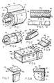
- FIG. 1 shows a portion of an insulation segment 10 installed around pipe 12.
- Pipe 12 may be any conventional hot or cold water pipe or steam pipe or pipe for carrying chemicals or petroleum products.
- Pipe 12 can be formed of any conventional material, such as copper, steel, plastic, aluminum or rubber.
- Segment 10 is comprised of a flame resistant, vapor barrier material.
- Segment 10 may have an outer layer of a plastic material such as polyvinylchloride (PVC) (not shown) but segment 10 typically comprises an outer flame retardant paper layer 16, a middle layer 17 of fiberglass yarns, and an inner metallized layer 18.
- PVC polyvinylchloride
- metallized layer 18 is secured to opposite sides of fiberglass layer 17 using a flame resistant laminating adhesive.
- the metallized layer can also be disposed between paper layer 16 and layer 17.
- metallized layer 18 is a layer of aluminum foil, while in another embodiment, metallized layer 18 is an aluminized polyester film.
- paper layer 16 is a high intensity, white, chemically treated kraft paper, and the weight of the paper is in the order of 0.073 kg/m2 (45 pounds per 3000 square feet).
- Layer 16 may contain an embedded scrim which produces a textured outer surface which has a raised pattern identical to the scrim pattern.
- Layer 17 typically, although not always, is comprised of fiberglass scrim yarns and has a tridimensional 5 ⁇ 5 fiberglass construction. Segment 10 is split along its entire length at slit 50, and slit 50 is adapted to be sealed along its length by a flap 52.
- Flat 52 typically is an extension of paper layer 16, or if layers 16 and 18 are laminated to form a single unit, flap 52 is an extension of the unit formed by layers 16 and 18.
- an adhesive strip 80 is provided on the undersurface of flap 52 for sealing of flap 52 to the outside surface of paper layer 16 adjacent slit 50.
- Strip 80 extends the entire length of flap 52 and is covered with a layer of release paper 81 prior to sealing of the flap.
- Adhesive strip 80 typically is comprised of a pressure sensitive adhesive, such as an isooctyl acrylate polymer.
- paper layer 16 has a tendency to absorb moisture from its environment, both before and after sealing of flap 52 thereto. Also, if segment 10 has an outer PVC coating, moisture tends to form on the surface thereof. In prior art segments, if the outer layer is moist at the location adjacent slit 50, adhesive layer 80 is not tightly and optimally secured thereto. In addition, if absorption of moisture occurs after sealing of flap 52 to the outside of segment 10, such moisture can cause layer 16 to begin to disintegrate or delaminate. Flap 52 has a natural tendency, because of its method of manufacture, to tend to open up or lift off its point of attachment.
- flap 52 will rise off the insulation segment, or "fish mouth", taking a portion of layer 16 with it, thus providing an air gap through which heat can enter or escape. "Fish mouthing” is further accelerated if layer 16 has a textured outer surface, because the adhesive may only bond to the 25% of the surface that is raised, if enough pressure is not applied to the adhesive. Also, if the outer surface of segment 10 is formed of PVC, the pressure of moisture can also cause flap 52 to "fish mouth.”
- strip 60 of a coating material which extends along nearly the entire length of segment 10 and which is disposed closely adjacent slit 50 on paper layer 16.
- Strip 60 typically has a width sufficiently great that it extends to the outer edge 83 of flap 52 when flap 52 is folded over slit 50 and is secured to the outer surface of segments 10. Typically, this width is about 38.1 to 76.2 mm (one and one half to about three inches).
- adhesive layer 80 is secured along its entire length only to strip 60.
- Strip 60 prepares the surface for the adhesive, and for a paper layer 16, the paper layer all the way down to the laminating adhesive so that water cannot penetrate into layer 16 at the point where flap 52 is secured. A smooth, flat surface is provided to which the adhesive can bond. In this manner, delamination and disintegration of layer 16 adjacent flap 52 are eliminated.
- the coating material used for strip 60 preferably is nonblocking when cured and is moisture resistant. Also, it may have the following properties: sufficiently flexible so as not to crack when bent or folded; remains flexible within the range of temperatures from about 65°C (150°F.) to about -6°C (-20° F) of bonding to a pressure sensitive adhesive such as an isooctyl acrylate polymer; capable of being absorbed by paper; capable of adhering to paper, a plastic material such as PVC and metallized surfaces; not capable of adhering to dirt; transparent (although this is not an essential property); and no static cling so it will not attract dust.
- Materials which can be used for strip 60 are cured, adhesive systems. The preferred material is prepared from a cured, two component, solvent based linear, saturated polyester adhesive system.
- a pneumatically pressurized roller tip having a knurled surface can be used to apply the mix in a manner similar to that used with gravure equipment.
- An example of an acceptable pressurized roller is that manufactured by Aro Corporation. One Aro Center, Bryan, Ohio 43506, under Model No. 463122-3. Large knurling is used on the roller to provide the desired amount of adhesive. Typically, the roller is about 75 mm (3 inches) wide.
- the mixture may also be sprayed on the surface of paper layer 16 using a conventional pneumatically driven spray system. Thereafter, the solution is fully cured to drive off all solvents until the resulting strip 60 is nonblocking.
- strip 60 is cured using a conventional drying oven, such as an infrared oven provided with an air flow therethrough.
- the oven is maintained at a temperature in a range of from about 93°C (200° F.) to about 121°C (250° F.)
- a preferred coating material is prepared from a two component, solvent based adhesive system, in which the primary component comprises a linear saturated polyester base and a toluol/methylene chloride solvent.
- This primary component has about 27% total solids, a Brookfield viscosity of 900 to 1100 CPS, and it has a specific gravity of about 1.1 kilograms per liter. It is light straw in color. Its flash point is 18.8°C (66° F.)
- the other component of this system is a catalyst, and is preferably a polyfunctional aliphatic isocyanate resin dissolved in n-butyl acetate/xylene (1:1).
- the specific gravity of the preferred polyisocyanate compound is 1.06 kilograms per liter and contains approximately 25% ⁇ 2% volatiles by weight.
- NCO content is 16.5% to 0.5% and the viscosity is 250 mpa's.
- the free HDI monomer weight of the catalyst is 0.7% maximum, and the flash point is about 30 °C (87°F.) It is a clear, slightly yellow liquid.
- Suitable components may be purchased commercially from Bostik Chemical Division of the Emhart Fastener Group, Boston Street, Middleton. Massachusetts 01949. A suitable primary component is Bostik 7064, and a suitable catalyst is Boscodur No. 40.
- the primary component such as the Bostik 7064
- the primary component is diluted with methylene chloride or trichlorylethylene until it has a solids content of in the range of from about 28% to 38% by weight.
- a premix is then formed with the primary component and the catalyst.
- the primary component constitutes about four parts by volume of the premix, and the catalyst comprises about one part by volume of the premix.
- This premix is then blended in a known manner, such as by a lightening mixer, until a homogeneous solution is obtained, or until the polyisocyanate is totally in solution. Thereafter, this homogeneous solution is applied wet to the surface of paper layer 16 and cured, all as described above, to form strip 60.
- the solution is applied wet in sufficient amounts so that it will have a dry thickness in the range of from about 3.8 x 10 ⁇ 5m to 7.6 x 10 ⁇ 5m (1.5 mils to 3.0 mils), and a dry coating weight in the range of from about 40 to 80 grams/m2 (1.188 dry ounces per square yard to about 2.376 dry ounces per square yard).
- Shear tests were performed in which a strip of material coated with an adhesive, such as an isooctyl acrylate polymer was secured to a material such as that comprising a segment 10 having an outer paper layer 16.
- an adhesive such as an isooctyl acrylate polymer
- a material such as that comprising a segment 10 having an outer paper layer 16.
- One test was performed in which the paper layer was uncoated, and another test was performed in which the paper layer was coated with the cured linear saturated polyester material described herein.
- a 1 kilogram weight was applied in shear (at an angle of about 180° to the surface of paper layer 16) both to the flaps secured to the coated layer and to the uncoated layer.
- the weight was allowed to be suspended for a 15 minute period at room temperature 21.1°C (70° F.) and then the temperature was elevated to first 37.7°C (100° F.), then 65°C (150° F.), and then 93°C (200° F.) In this test, where no coating was present, the bond failed after 13 hours. For the coated paper, the bond held after 24 hours. When the temperature was raised to 65°C (150° F), the bond still held for an additional 72 hours. Finally, when the temperature was raised to 93°C (200° F.), the bond continued to hold for an additional 110 hours, at which point the test was stopped. The same test was repeated using a 2 kilogram weight in shear.
- Another acceptable coating material can be prepared from a two component, solvent based adhesive system in which the primary component again comprises a linear saturated polyester base and chlorinated solvents.
- the total solids content of this primary component is higher than that set forth in Example 1, and is 36%, ⁇ 1.
- the Brookfield visccsity is 3500 CPS ⁇ 500, and the specific gravity is about 10.72 pounds per gallon (1:29 kilograms per liter).
- the primary component has no flash point, and is light straw in color.
- the other component of the system is a catalyst, which is the same catalyst set forth in Example 1. Again, this catalyst is a polyfunctional aliphatic isocyanate resin dissolved in n-butyl acetate-xylene (1:1).
- Suitable components may be purchased Commercially from Bostik Chemical Division of the Emhart Fastener Group, Boston Street, Middleton, Massachusetts 01949.
- a suitable base is Bostik 7205
- a suitable catalyst is Boscodur No. 40.
- a premix is formed in which the primary component constitutes about 20 parts by volume and the catalyst Constitutes about one part by volume. In all other respects, this coating material is prepared for use and applied in the same manner as set forth in Example 1.
- Another acceptable coating material can be prepared from a two component, solvent based adhesive system in which the primary component comprises a polyester resin base and methylethylketone and toluol solvents.
- the primary component has about 43% to 47% total solids, and a Brookfield viscosity of 1000 to 2000 CPS.
- the primary component has a specific gravity of about 7.95 pounds per gallon (0.95 kilograms per liter), and is light amber in color.
- the flash point of the primary component is about -7°C (18° F).
- the other component of this system is a catalyst, and is preferably a polyfunctional aliphatic isocyanate resin dissolved in n-butyl acetate/xylene (1:1). This catalyst is identical to that set forth in Example 1.
- Suitable components may be purchased commercially from Bostik Chemical Division of the Emhart Fastener Group, Boston Street, Middleton, Massachusetts 01949.
- a suitable base is Bostik 7237
- a suitable catalyst is Boscodur No. 40.
- the primary component is mixed with the catalyst in a ratio of about 20 parts by volume to 1 part by volume for the primary component for the catalyst. In all other respects, this coating material is prepared for use and applied in the same manner as set forth in Example 1.
- Another coating material can be prepared from a two component, solvent based adhesive system in which the primary component comprises a polyester resin base and a methylethylketone solvent.
- This primary component has about 70% ⁇ 1 total solids, a Brookfield viscosity of 3000 CPS ⁇ 1000 CPS and a specific gravity of about 1.08 kg/liter (9 pounds per gallon).
- the flash point of the primary component is -8.8°C (16° F).
- the other component of this system is a catalyst, and is preferably a polyfunctional aliphatic isocyanate resin dissolved in n-butyl acetate/xylene (1:1). This catalyst is identical to that set forth in Example 1.
- Suitable components may be purchased commercially from Bostik Chemical Division of the Emhart Fastener Group, Boston Street, Middleton, Massachusetts 01949.
- a suitable base is Boslam 7885
- a suitable catalyst is Boscodur No. 40. This primary component is mixed with the catalyst so that the catalyst comprises approximately 10% to 12% of the total mix by weight. In all other respects, this coating material is prepared for use and applied in the same manner as set forth in Example 1.
- Another coating material can be prepared from a single component, solvent based adhesive which comprises a urethane base and a methylethylketone/toluol solvent.
- This adhesive has about 20% ⁇ 1 total solids, a Brookfield viscosity of about 5 to 600 CPS and a specific gravity of 7.3 pounds per gallon (.87 kilograms per liter).
- the adhesive is clear in color, has a medium syrup consistency, and has a flash point of about 16°C (35° F.)
- a suitable adhesive may be purchased commercially from Bostik Chemical Division of the Emhart Fastener Group, under the product designation Bostik 7376. In all other respects, this coating material is prepared for use and applied in the same manner as set forth in Example 1.
- Another coating material can be prepared from a single component, solvent based adhesive which comprises a vinyl base carried in a solvent comprising about 91% methylethylketone and about 9% toluene.
- This adhesive has about 35% total solids, a Brookfield viscosity of about 1000 CPS and a specific gravity of 0.93 kg/liter (7.8 pounds per gallon).
- This adhesive has a flash point of about -6°C (20° F.), and an appearance which is clear and straw-colored as a liquid, but colorless as a film.
- a suitable adhesive may be purchased from National Starch And Chemical Corporation, The Adhesives Division, Finderne Avenue, P. O. Box 6500, Bridgewater, New Jersey 08807, under the product designation Duro-flex 30-1278. In all other respects, this coating material is prepared for use and applied in the same manner as set forth in Example 1.
- the layer of adhesive is provided in a roll and secured to a conventional silicone coated release paper 122 having differential release characteristics.
- a strip of such release paper 122 can be cut from the roll at the job site and applied as illustrated in FIG. 2.
- the side of release paper 122 having the easy release is disposed so as to face upwardly away from flap 52, while the side of release paper 122 having a tighter release retains the adhesive layer which is applied to flap 52. Thereafter, when it is desired to seal flap 52 to strip 60 on segment 10, release paper 122 can be removed from flap 52, leaving behind adhesive layer 80 secured directly to flap 52 and exposed for application to strip 60.
- strip 120 extends along the entire length of flap 52 from one end of segment 10 to the other end.
- the width of strip 120 is in the range of from about 38.1 to 76.2 mm (1-1/2 inches to about 3 inches).
- the strip of width 120 is about the same as the width of strip 60 and extends to the outer edge 83 of flap 52.
- Strip 120 is formed of the same material as is strip 60, preferably, a linear saturated polyester, and it is applied in the same manner as strip 60. The same requirements which apply to strip 60 also apply to strip 120.
- This embodiment overcomes problems associated with the tendency of the undersurface of flap 52 to absorb moisture from its environment both before and after sealing of flap 52 to the outside surface of paper layer 16 adjacent slit 50, and associated with a textured surface.
- strip 122 prevents "fish mouthing" which could result from disintegration of flap 52 on its underside where adhesive layer 80 is secured thereto.
- Segment 10 often is used with a plurality of other such segments to insulate a pipe along its length.
- Exemplary segments 10 and 14 are shown in abutting relationship in FIG. 4 for a section of pipe 12.
- Segments 10 and 14 abut one another at respective ends 22 and 24.
- the space between ends 22 and 24 typically is sealed by butt strip tape 20 which is wrapped about the circumference of segments 10 and 14 and which is secured to itself by overlapping end 17 with end 19.
- Strip 62 extends around the entire circumference of segments 10 and 14, including the outer surface of flap 52.
- the actual width of strip 62 is a function of the width of tape 20, and typically, strip 62 has a width of about two or three inches.
- Strip 62 is formed of the same material and is applied in the same manner as is strip 60.
- butt strip tape 20 A preferred embodiment of butt strip tape 20 is shown in FIGS. 3 through 5.
- Butt strip tape 20 usually has a structure which is similar to that of segments 10 and 14 so as to be compatible therewith, except that tape 20 includes a thinner fiberglass layer. However, it is not necessary that tape 20 have the same identical structure as segments 10 and 14 and other structures are possible.
- tape 20 includes a layer 26 of paper, a layer 28 of fiberglass, a metallized layer 30, a layer 32 of a pressure sensitive adhesive, and a layer 54 of release paper.
- paper layer 26 contains a fiberglass scrim, providing the tape with a textured surface having a raised pattern in accordance with the scrim pattern.
- Paper layer 26 and fiberglass layer 28 are secured together using laminating adhesive 34, while fiberglass layer 28 and metallized layer 30 are secured together by laminating adhesive 36.
- Paper layer 26 again is preferably a high intensity, white, chemically treated kraft paper which is flame retardant.
- Fiberglass layer 28 is made of fiberglass yarns, and typically is woven to form either a tridirectional or diamond patterned weave, or a scrim having a square weave such as a 5 ⁇ 5 scrim.
- Laminating adhesives 34 and 36 can be any conventional, thermo-setting, flame-retardant adhesives which are suitable for laminating fiberglass to paper and to polyester or metal.
- Layer 30 can be either a layer of aluminum foil, or a layer of a metallized polyester film.
- Release paper 54 can be any conventional release paper which is suitable for use with an acrylic adhesive.
- the adhesive layer typically is an isooctyl, acrylate polymer adhesive.
- butt strip tape 20 is provided in segments of a premeasured length, which is a function of the circumference of segment 10 with which tape 20 is to be used.
- the circumference of segment 10 is in turn a function of the diameter of pipe 12 and of the desired thickness of layer 17.
- Adjacent one end of each segment of tape 20, a strip 66 of a coating material is provided on the outer surface of paper layer 26.
- Strip 66 preferably is spaced about 25 mm (1 inch) from the end of the tape segment although it could also extend up to the end of the tape segment.
- Strip 66 is formed of the same material as strips 60 and 62, preferably a linear saturated polyester, and strip 66 may be applied in the same manner.
- the tape is formed in a continuous length, and an intermittant spray system is used to apply the coating at the proper intervals and widths along its length. The length of tape is later cut into appropriate segments.
- Strip 66 can be of any width, but typically strip 66 has a width of about 50-75 mm (two or three inches).
- Strip 66 is provided on an end of a segment of tape 20 which is to be directly secured to the outer surface of segments 10 and 14.
- Duct board 70 typically comprises a flame retardant paper layer 72, a layer 76 of fiberglass yarns, and a metallized layer 74. Typically, the paper layer and the metallized layer are secured to opposite sides of the fiberglass layer 76 with a flame resistant laminating adhesive.
- Fiberglass layer 76 is formed of a high density fiberglass wool and provides duct board 70 with its desired rigidity.
- FIG. 6 shows the use of duct board 70 in conjunction with a typical duct 78 having a rectangular cross section.
- duct 78 top and bottom panels 88 and side panels 86 of duct board 78 are provided. Panes 88 and 86 are trimmed to the appropriate size for use in conjunction with duct 78.
- Side edge 90 of panel 88 adjoins and is sealed to side edge 92 of panel 86 to provide the desired seal about duct 78.
- edge 90 of panel 88 overlaps edge 92 of panel 86 so that layer 76 of panel 88 remains exposed.
- Tape 94 is used to seal together edges 90 and 92.
- Tape 94 is generally applied from a roll and tape 94 extends in its lengthwise direction along and parallel to edges 90 and 92. This particular application of the tape requires that the tape be creased or folded in its direction of elongation as shown in FIG. 8 so that one half is disposed on edge 90, while another portion thereof is secured to edge 92. Because of its method of manufacture, when folded in this lengthwise direction, tape 94 is less flexible than when folded in its transverse direction. This is because a lengthwise fold is transverse to the machine direction of the tape. As a result, the tape has a tendency to try to retain its original flat condition. When tape 94 is applied, a shear stress thus results along edges 90 and 92 between the tape and the insulation surface to which it is secured.
- Metallized layer 74 may collect water by condensation or by direct application before application of tape 94 thereto. As a consequence the bond between tape 94 and layer 74 is weak. Because of the shear stress between tape 94 and paper layer 74, tape 94 has a tendency to release from either edge 90 or edge 92. As a result, a seal is difficult to maintain, especially in humid conditions, and the tape and insulation panels frequently have to be replaced. This problem is aggrevated by the fact that the duct board is almost always left in an exposed situation, and frequently is found in basements or other locations where the moisture content of the air is high.
- strips 96 and 98 are formed of the same material as are strips 60 and 62 of segment 10, which is preferably a linear saturated polyester. Strips 96 and 98 are also applied in the same manner as are strips 60 and 62. Ideally, the width of strips 96 and 98 is sufficient to accommodate the entire width of tape 94 when used in the arrangement shown in FIG. 8. A typical width is two to three inches.
- Tape 94 is also used to seal the spaces between abutting longitudinal ends 99 of panels 86 and 88. Tape 94 typically is wrapped all the way around the perimeter of duct 78. Although the tendency for the tape to come loose at such a joint is not as great as long edges 90 and 92, because the tape is folded only transversely or parallel to the machine direction, a poor bond due to dirt or moisture may still allow tape 94 to eventually release from the surface of panels 86 and 88. Therefore, in an alternative embodiment, a strip 100 of coating material is provided along the edge of each longitudinal end 99 of each panel 86 and 88. Strips 100 are formed of the same material and applied in the same manner as are strips 96 and 98.
- Blanket insulation 126 is provided in rolls, and is generally highly flexible.
- Blanket insulation 126 typically has the same structure as duct board, as shown in FIG. 8 and typically comprises a flame retardant paper layer 128, a layer of loosely woven fiberglass yarns 130, and a metallized layer 132.
- the paper layer and the metallized layer are secured to opposite sides of fiberglass layer 130 with a flame resistant laminating adhesive.
- metallized layer 132 may be disposed between paper layer 128 and fiberglass layer 130.
- Fiberglass layer 130 is formed of a low density fiberglass wool and allows blanket insulation 126 to have the desired flexibility. During installation of blanket insulation 126 on a typical duct (not shown), either paper layer 128 or metallized layer 132 may be positioned to be on the outside surface facing away from the duct.
- lateral edges of the blanket insulation are placed in side by side relation along a duct and are secured together using segments of tape, such as those shown in FIGS. 3-5.
- This seal is subject to compromise because of moisture or dirt, as previously described for similar insulation structures.
- This problem is overcome by providing a strip 134 of a coating material along the lateral edges of the entire roll of blanket insulation 126 either on paper layer 128 or on metallized layer 132.
- This strip 134 of a coating material has the same composition as strip 60, and is applied in the same manner.
- tape segments used to seal edges 136 of adjoining segments of blanket insulation typically overlap one another in an end to end relation. Therefore, tape segments having a layer of a coating material at one end on the paper layer, such as those shown in FIGS. 3-5, are preferably used, so that the overlapping portions of the segments are secured tightly to one another, and do not suffer from the problems of delamination and disintegration of the paper layer.
- the linear saturated polyester material used for forming the strips on each of the embodiments of this invention is ideally suited for such a use because it contains all of the required properties. It is moisture resistant, flexible, flexible at high or low temperatures, it will bond to pressure sensitive adhesives, it is absorbed by paper, it will adhere to paper, PVC or a metallized surface, it is clear, it has no static cling, and it does not remain sticky once it has been cured, and it provides a flat, smooth surface to which an adhesive will bond over its entire surface.
- This invention overcomes serious problems with the use of tape systems in pipe and duct insulation applications. This invention allows the creation of a seal of high integrity which need not be repaired or replaced for long periods of time and which meets existing United States Government specifications.
Landscapes
- Engineering & Computer Science (AREA)
- General Engineering & Computer Science (AREA)
- Mechanical Engineering (AREA)
- Laminated Bodies (AREA)
- Insulating Bodies (AREA)
- Adhesive Tapes (AREA)
- Adhesives Or Adhesive Processes (AREA)
- Thermal Insulation (AREA)
Claims (18)
- Isoliersystem für eine langgestreckte Fluidleitung (12, 78) mit Mitteln (10, 70, 126) zu deren Isolierung, wobei die Isoliermittel eine Isolierschicht (17, 76, 130), eine nach außen weisende obere Schicht (16, 72, 128) und einen Spalt (50, 23, 93, 95) umfassen, der durch ein Paar voneinander beabstandeter, einander parallel gegenüberliegender Ränder (47, 49; 22, 24; 90, 92; 99) definiert ist; und mit Verschlußmitteln (52, 20, 94), die eine Schicht (80, 32, 89) eines auf Druck reagierenden (drucksensitiven) Klebers zum Verschließen des genannten Spaltes aufweisen, wobei sich die Verschlußmittel quer über den Spalt zwischen den zwei genannten Rändern erstrecken, gekennzeichnet durch einen Streifen (60, 92, 96, 98, 100, 134) eines wasserbeständigen, nichtklebenden, auf der oberen Schicht (16, 72, 128) der genannten Isoliermittel angebrachten Überzugsmaterials, welches dicht an mindestens einen der genannten zwei Ränder angrenzt, welche den Spalt definieren und sich über die Länge des genannten Spaltes erstrecken, wobei der genannte Streifen des Überzugsmaterials angepaßt ist zur Aufnahme der Schicht (80, 32, 89) des auf Druck reagierenden, auf den genannten Verschlußmitteln angebrachten Klebers.
- Isoliersystem nach Anspruch 1, wobei die Isoliermittel (10) einen im wesentlichen zylindrischen Abschnitt zum Einhüllen der Leitung umfassen, dadurch gekennzeichnet, daß sich der Spalt (50) im wesentlichen der Länge nach in Richtung der Längsausdehnung der Leitung erstreckt.
- Isoliersystem nach Anspruch 2, dadurch gekennzeichnet, daß die Verschlußmittel eine Klappe (52) beinhalten, die als Verlängerung der genannten oberen Schicht ausgebildet ist und sich vom genannten anderen Rand aus erstreckt.
- Isoliersystem nach Anspruch 3, gekennzeichnet durch einen zweiten Streifen (120) eines wasserbeständigen, nichtklebenden, auf der Unterseite der Klappe (52) angeordneten Überzugsmaterials, der sich in gegenüberliegender Zuordnung zum Streifen (60) des nahe dem genannten Spalt angebrachten Überzugsmaterials befindet, wobei der zweite Streifen (120) eine Schicht eines darauf angebrachten, auf Druck reagierenden Klebers aufweist.
- Isoliersystem nach Anspruch 1, bei dem die Isoliermittel zwei im wesentlichen zylindrische Isolierabschnitte (10) umfassen, die aneinanderstoßende Enden zum Abdecken der Leitung aufweisen, dadurch gekennzeichnet, daß das genannte Paar von Rändern auf den aneinanderstoßenden Enden der genannten Abschnitte ausgebildet ist, der Spalt sich im wesentlichen quer zur Richtung der Längsausdehnung der Leitung erstreckt und die Verschlußmittel ein auf Druck reagierendes Klebeband (20) umfassen, das an dem einen und an dem anderen der genannten Ränder befestigt ist.
- Isoliersystem nach Anspruch 5, dadurch gekennzeichnet, daß das auf Druck reagierende Klebeband einen Bandabschnitt von vorbestimmter Länge mit einer ersten nichtklebenden Seite eine zweite Seite mit einem auf Druck reagierenden Kleber (32) und einen Streifen (66) eines Überzugsmaterials umfaßt, der nahe einem Ende des genannten Bandabschnitts auf dessen erster Seite angeordnet ist, und daß der genannte Bandabschnitt so um die Isolierabschnitte gewickelt wird, daß die zweite Seite des genannten Bandabschnitts mit dem Streifen (66) auf dem genannten einen Ende des Bandabschnitts gesichert ist.
- Isoliersystem nach Anspruch 1, bei dem die Isoliermittel ein Paar im wesentlichen ebener, in einem Winkel zueinander stehender Platten (70) umfassen, wobei einer der genannten Ränder auf einer der genannten Platten angeordnet ist und der andere der genannten Ränder auf der anderen der besagten Platten angebracht ist, dadurch gekennzeichnet, daß die Verschlußmittel ein auf Druck reagierendes Klebeband (94) beinhalten, das an dem einen genannten Rand und an dem anderen besagten Rand befestigt ist.
- Isoliersystem nach Anspruch 1, bei dem die Isoliermittel im wesentlichen ein Paar zusammenstoßender, im wesentlichen in gleicher Ebene angeordnete Platten umfassen, wobei das genannte Ränderpaar auf den zusammenstoßenden Enden der genannten Plattenpaare angeordnet ist, dadurch gekennzeichnet, daß die Verschlußmittel ein auf Druck reagierendes Klebeband (94) beinhalten, das an dem einen genannten Rand und an dem anderen besagten Rand befestigt ist.
- Isoliersystem nach Anspruch 1, dadurch gekennzeichnet, daß die Isoliermittel eine flexible Mattenisolierung umfassen, welche angepaßt ist zum Herumwickeln um die Fluidleitung.
- Isoliersystem nach Anspruch 1, bei dem die langgestreckte Fluidleitung ein Rohr ist und die Mittel zur Isolierung des Rohres einen langgestreckten zylindrischen Abschnitt (10) eines Isoliermaterials zum Herumwickeln um das Rohr umfassen, wobei ein zentral angeordneter Kanal sich entlang der Länge des genannten Abschnitts in Richtung dessen Längsausdehnung erstreckt und der Kanal an die Aufnahme des Rohres angepaßt ist, wobei sich ein Spalt (50) entlang der Länge des genannten Abschnitts von dessen Außenfläche zum genannten zentralen Kanal erstreckt, damit das Rohr in den genannten Kanal eingefügt werden kann, wobei die Verschlußmittel einschließlich einer Klappe (52) auf dem genannten Abschnitt zum Verschließen des Spaltes angeordnet sind, und wobei die genannte Klappe die Schicht (80) eines auf Druck reagierenden, auf ihrer Innenfläche angeordneten Klebers aufweist, dadurch gekennzeichnet, daß der Streifen (60) eines wasserbeständigen, nichtklebenden Überzugsmaterials nahe dem Spalt (50) auf einer Außenfläche des genannten Abschnitts angeordnet ist und angepaßt ist, die Klebeschicht der Klappe aufzunehmen.
- Isoliersystem nach Anspruch 10, gekennzeichnet durch einen zweiten Streifen (120) eines wasserbeständigen, nichtklebenden Überzugsmaterials, der auf der Unterseite der Klappe (52) gegenüber dem Streifen (60) des Überzugsmaterials nahe dem genannten Spalt angeordnet ist, wobei der zweite Streifen (120) eine Schicht eines darauf angebrachten, auf Druck reagierenden Klebers aufweist.
- Isoliersystem nach Anspruch 10, wobei der langgestreckte Abschnitt ein erstes und ein in Richtung der Längsausdehnung des genannten Abschnitts davon beabstandetes zweites Ende aufweist, dadurch gekennzeichnet, daß das genannte erste Ende und das genannte zweite Ende jeweils mit einem Streifen eines wasserbeständigen, nichtklebenden Überzugsmaterials versehen sind, der sich im wesentlichen um den gesamten Umfang des genannten Abschnitts auf dessen Außenfläche in dichtem Abstand zum besagten Ende erstreckt.
- Isoliersystem nach Anspruch 1, wobei der Isolierabschnitt einen ersten zylindrischen Isolierabschnitt (10) zum Herumwickeln um ein Rohr, wobei der genannte erste Abschnitt ein erstes Ende (22) aufweist; einen zweiten zylindrischen Isolierabschnitt (14) zum Herumwickeln um das Rohr, wobei der genannte zweite Isolierabschnitt ein nahe und dicht an das genannte erste Ende (22) des genannten ersten Abschnitts anstoßendes erstes Ende (24) aufweist, um den Spalt (23) zwischen ihnen zu definieren; und ein drucksensitives Klebeband (20) zum Schließen des Spaltes (23) zwischen dem genannten ersten Ende (22) des genannten ersten Abschnitts und dem genannten ersten Ende (24) des genannten zweiten Abschnitts umfaßt, gekennzeichnet durch einen ersten Streifen (62) eines wasserbeständigen, nicht-klebenden Überzugsmaterials, der um den Außenumfang des genannten ersten Abschnitts angeordnet und dicht an dessen genanntem erstem Ende (22) angrenzend positioniert ist, einen zweiten Streifen (62) eines wasserbeständigen, nichtklebenden Überzugsmaterials, der um den Außenumfang des genannten zweiten Abschnitts angeordnet und dicht an dessen genanntes erste Ende (24) angrenzend positioniert ist, wobei der genannte erste Streifen und genannte zweite Streifen angepaßt sind, das besagte auf Druck reagierende Klebeband (20) zum Befestigen des genannten Bandes an dem besagten ersten Ende (22) des genannten ersten Abschnitts, beziehungsweise an dem genannten ersten Ende (24) des genannten zweiten Abschnitts aufzunehmen.
- Isoliersystem nach Anspruch 11, dadurch gekennzeichnet, daß das besagte Klebeband (20) eine Innenfläche mit einem auf ihr aufgetragenen, auf Druck reagierenden Kleber, eine Außenfläche und einen Streifen (60) eines wasserbeständigen, nicht-klebenden, auf der genannten Außenfläche nahe an ihrem einen Ende angeordneten Überzugsmaterials umfaßt, wobei das genannte eine Ende angepaßt ist, um von der genannten Innenfläche an einem gegenüberliegenden Ende davon überlappt zu werden.
- Isoliersystem nach irgendeinem der vorstehenden Ansprüche, dadurch gekennzeichnet, daß das besagte Überzugsmaterial einen ausgehärteten Kleber aufweist.
- Isoliersystem nach Anspruch 15, dadurch gekennzeichnet, daß der genannte Kleber eine Trockendicke im Bereich von etwa 3,8 x 10⁻⁵ bis 7,6 x 10⁻⁵ m (1,5 bis 3,0 mils) und ein spezifisches Trockenschichtgewicht im Bereich von etwa 40 bis 80 g/m² (1,188 bis etwa 2,376 dry ounces per square yard) aufweist.
- Isoliersystem nach Anspruch 13 oder 15, dadurch gekennzeichnet, daß der Streifen des Überzugsmaterials einen gehärteten, linear gesättigten Polyesterkleber umfaßt.
- Isoliersystem nach Anspruch 15, dadurch gekennzeichnet, daß der linear gesättigte Polyesterkleber aus zwei Komponenten hergestellt ist, die einen in Lösung gehaltenen, linear gesättigten Polyester und einen Polyisocyanat-Katalysator beinhalten.
Priority Applications (1)
| Application Number | Priority Date | Filing Date | Title |
|---|---|---|---|
| AT88308483T ATE90433T1 (de) | 1987-09-15 | 1988-09-14 | Isolierung mit einer an einem klebeband haftenden oberflaeche. |
Applications Claiming Priority (2)
| Application Number | Priority Date | Filing Date | Title |
|---|---|---|---|
| US07/096,660 US4842908A (en) | 1987-09-15 | 1987-09-15 | Insulation with tape adhering surface |
| US96660 | 1987-09-15 |
Publications (3)
| Publication Number | Publication Date |
|---|---|
| EP0308191A2 EP0308191A2 (de) | 1989-03-22 |
| EP0308191A3 EP0308191A3 (en) | 1990-02-07 |
| EP0308191B1 true EP0308191B1 (de) | 1993-06-09 |
Family
ID=22258453
Family Applications (1)
| Application Number | Title | Priority Date | Filing Date |
|---|---|---|---|
| EP88308483A Expired - Lifetime EP0308191B1 (de) | 1987-09-15 | 1988-09-14 | Isolierung mit einer an einem Klebeband haftenden Oberfläche |
Country Status (6)
| Country | Link |
|---|---|
| US (1) | US4842908A (de) |
| EP (1) | EP0308191B1 (de) |
| JP (1) | JPS6474385A (de) |
| AT (1) | ATE90433T1 (de) |
| CA (1) | CA1332916C (de) |
| DE (1) | DE3881619T2 (de) |
Families Citing this family (34)
| Publication number | Priority date | Publication date | Assignee | Title |
|---|---|---|---|---|
| US5104701A (en) * | 1987-09-15 | 1992-04-14 | Venture Tape Corp. | Insulation with tape adhering surface and tape therefor |
| US4971644A (en) * | 1989-12-11 | 1990-11-20 | John Mahn, Sr. | Reverse method of applying heat activated ornamental transfer |
| US5188883A (en) * | 1990-03-22 | 1993-02-23 | Northern Telecom Limited | Composite tape structures |
| US5421371A (en) * | 1993-04-19 | 1995-06-06 | Nmc Of North America, Inc. | Multi-layered bonded closure system for foam tubes or profiles |
| US5407515A (en) * | 1993-12-17 | 1995-04-18 | Singer; Steven | Lamination method and apparatus using edge bonding |
| CA2141527C (en) * | 1994-03-24 | 2001-03-13 | Dennis G. Fontanilla | Butt strip tape for insulation application |
| US5934337A (en) * | 1995-06-06 | 1999-08-10 | Fiala; Anthony | Field installed insulating system |
| US5783274A (en) * | 1995-07-07 | 1998-07-21 | Morgan Adhesives Company | Pressure sensitive adhesive closure system for foam insulation |
| GB2311114B (en) * | 1996-03-15 | 1999-04-28 | T & N Technology Ltd | Convoluted flexible protective sleeves |
| US5840392A (en) * | 1997-09-04 | 1998-11-24 | Clark; Kevin H. | Self-adhering duct insulation board |
| US6527014B1 (en) * | 1999-11-30 | 2003-03-04 | Owens Corning Fiberglas Technology, Inc. | Flexible duct insulation having improved flame resistance |
| US6428651B1 (en) | 2000-04-27 | 2002-08-06 | Plastic Technology, Inc. | Method and apparatus for applying adhesives to the edges of a slit tube |
| US20030208976A1 (en) * | 2002-05-08 | 2003-11-13 | Tommie Ann Buchanan (Six Mile, Sc) | Prefabricated insulation for HVAC ductwork and other fluid conduits |
| US20040151922A1 (en) * | 2002-12-27 | 2004-08-05 | Cohen Lewis S. | Facing having increased stiffness for insulation and other applications |
| US20040161615A1 (en) * | 2002-12-27 | 2004-08-19 | Cohen Lewis S. | Facing having increased stiffness for insulation and other applications |
| US20040126597A1 (en) * | 2002-12-27 | 2004-07-01 | Cohen Lewis S. | Facing for insulation and other applications |
| MXPA05006982A (es) * | 2002-12-27 | 2006-02-22 | Venture Tape Corp | Revestimiento para aislamiento y otras aplicaciones. |
| US6783830B2 (en) | 2003-01-23 | 2004-08-31 | Venture Tape Corp | Adhesive tape structure for use with insulation jackets |
| US6782922B1 (en) * | 2003-05-30 | 2004-08-31 | John Manville International, Inc. | Coated fibrous pipe insulation system |
| US7199763B2 (en) * | 2004-05-03 | 2007-04-03 | Lockheed Martin Corporation | Ground proximity antenna system |
| US20070207305A1 (en) * | 2006-03-06 | 2007-09-06 | York International Corporation | Panel construction for an air handling unit |
| US20070204752A1 (en) * | 2006-03-06 | 2007-09-06 | York International Corporation | Base construction for an air handling unit |
| GB2442240A (en) * | 2006-09-29 | 2008-04-02 | Specialist Insulation Ltd | Insulating products |
| US8104519B1 (en) * | 2010-08-13 | 2012-01-31 | Johns Manville | Pipe insulation product with charge dissipater |
| US8141594B2 (en) * | 2010-08-13 | 2012-03-27 | Johns Manville | Pipe insulation products and methods |
| WO2010151774A1 (en) | 2009-06-25 | 2010-12-29 | Nomaco Inc. | Self-adjusting insulation, including insulation particulary suited for pipe or duct |
| US20110047908A1 (en) * | 2009-08-28 | 2011-03-03 | Brusman Bryan Daniel | High-strength insulated building panel with internal stud members |
| US8245381B2 (en) * | 2009-11-30 | 2012-08-21 | Owens Corning Intellectual Capital, Llc | Method of providing flexible duct having different insulative values |
| WO2013170250A1 (en) | 2012-05-11 | 2013-11-14 | Nomaco Inc. | Insulation systems employing expansion features to insulate elongated containers subject to extreme temperature fluctuations, and related components and methods |
| US9702147B2 (en) * | 2013-01-07 | 2017-07-11 | Clifford Eugene Babson | Panels for framing and constructing a building structure |
| US10150251B2 (en) | 2013-02-22 | 2018-12-11 | Aeroflex Usa | Connecting systems for adjacent ends of insulation tubing |
| DE102013005221A1 (de) * | 2013-03-27 | 2014-10-02 | L'isolante K-Flex S.R.L. | Thermoplastische Folie |
| CN106931638B (zh) * | 2017-04-01 | 2023-03-10 | 烟台通天达风机制造有限公司 | 聚能生热高温热风机 |
| CN111043441B (zh) * | 2019-11-08 | 2021-06-01 | 沪东中华造船(集团)有限公司 | 一种船用管件法兰防护用板材结构再利用方法 |
Family Cites Families (20)
| Publication number | Priority date | Publication date | Assignee | Title |
|---|---|---|---|---|
| US2797731A (en) * | 1955-10-06 | 1957-07-02 | Monsanto Chemicals | Method for preventing moisture condensation on cold pipes |
| US2957724A (en) * | 1958-02-03 | 1960-10-25 | Web Wilson Oil Tools Inc | Tool safety latch |
| CH443822A (de) * | 1965-09-02 | 1967-09-15 | Meier Schenk Arthur | Verfahren zur äusseren Abdeckung und dampfdichten Abdichtung der Isolierung isolierter Wärmeträgerrohre und Mantel zur Durchführung dieses Verfahrens |
| US3497383A (en) * | 1967-08-22 | 1970-02-24 | Minnesota Mining & Mfg | Electrically conductive adhesive tape |
| US3770556A (en) * | 1970-08-07 | 1973-11-06 | Reychem Corp | Wraparound closure sleeve |
| FR2212787A5 (de) * | 1973-01-03 | 1974-07-26 | Martin Francois | |
| US3876454A (en) * | 1973-03-28 | 1975-04-08 | Minnesota Mining & Mfg | Linerless pressure-sensitive adhesive tape having elastomeric backing |
| US3941159A (en) * | 1974-10-31 | 1976-03-02 | Wolcott Toll | Insulation assembly for a tubular conduit pipe |
| US4022248A (en) * | 1975-09-24 | 1977-05-10 | Owens-Corning Fiberglas Corporation | Pipe having insulating material and cover and having two strips of self-sealing adhesive material |
| US4060664A (en) * | 1975-12-08 | 1977-11-29 | Minnesota Mining And Manufacturing Company | Bonded composite structures |
| US3993833A (en) * | 1976-01-19 | 1976-11-23 | Minnesota Mining And Manufacturing Company | Polyurethane foam-backed pressure-sensitive adhesive tape |
| US4264388A (en) * | 1977-09-29 | 1981-04-28 | Morgan Adhesives Co. | Method for application of composite pressure sensitive adhesive |
| US4584217A (en) * | 1977-09-29 | 1986-04-22 | Morgan Adhesives Company | Composite pressure sensitive adhesive construction |
| US4181765A (en) * | 1978-09-27 | 1980-01-01 | Harmony Richard C | Insulator for canned drinks |
| US4243453A (en) * | 1979-05-14 | 1981-01-06 | Morgan Adhesives Company | Methods for application and use of a composite pressure sensitive adhesive construction |
| US4522870A (en) * | 1982-11-04 | 1985-06-11 | Minnesota Mining And Manufacturing Company | Linerless double-coated pressure-sensitive adhesive tape |
| US4513039A (en) * | 1982-11-04 | 1985-04-23 | Minnesota Mining And Manufacturing Company | Composite of separable pressure-sensitive adhesive tapes |
| US4605043A (en) * | 1984-08-08 | 1986-08-12 | Walter Allen Plummer | Snap-on heat insulating jacket and method for enclosing ducting |
| US4595615A (en) * | 1984-10-05 | 1986-06-17 | Venture Tape Corp. | Pipe insulation for cold weather applications |
| US4606957A (en) * | 1985-01-04 | 1986-08-19 | Venture Tape Corp. | Pipe insulation with flap for extreme weather applications |
-
1987
- 1987-09-15 US US07/096,660 patent/US4842908A/en not_active Expired - Lifetime
-
1988
- 1988-08-10 JP JP63199771A patent/JPS6474385A/ja active Pending
- 1988-09-13 CA CA000577195A patent/CA1332916C/en not_active Expired - Lifetime
- 1988-09-14 DE DE88308483T patent/DE3881619T2/de not_active Expired - Fee Related
- 1988-09-14 AT AT88308483T patent/ATE90433T1/de not_active IP Right Cessation
- 1988-09-14 EP EP88308483A patent/EP0308191B1/de not_active Expired - Lifetime
Also Published As
| Publication number | Publication date |
|---|---|
| EP0308191A2 (de) | 1989-03-22 |
| ATE90433T1 (de) | 1993-06-15 |
| JPS6474385A (en) | 1989-03-20 |
| EP0308191A3 (en) | 1990-02-07 |
| DE3881619T2 (de) | 1993-10-21 |
| DE3881619D1 (de) | 1993-07-15 |
| CA1332916C (en) | 1994-11-08 |
| US4842908A (en) | 1989-06-27 |
Similar Documents
| Publication | Publication Date | Title |
|---|---|---|
| EP0308191B1 (de) | Isolierung mit einer an einem Klebeband haftenden Oberfläche | |
| US4946732A (en) | Insulation with tape adhering surface | |
| US5104701A (en) | Insulation with tape adhering surface and tape therefor | |
| US4780347A (en) | Pipe insulation for cold weather applications | |
| EP0102570B1 (de) | Einrichtung zum Schutz gegen Hitze | |
| CA1178525A (en) | Sheet-like sealing web | |
| US4606957A (en) | Pipe insulation with flap for extreme weather applications | |
| US4726985A (en) | Reflective fibrous insulation | |
| US4172830A (en) | Waterproofing structure and method of using same | |
| CA1174024A (en) | Method of waterproofing roofs and the like | |
| KR101187962B1 (ko) | 단열 및 다른 용도를 위한 마감재 | |
| US20040126597A1 (en) | Facing for insulation and other applications | |
| US4729916A (en) | Thermal protective system | |
| JPH027826B2 (de) | ||
| US5085022A (en) | Building insulation | |
| US5001879A (en) | Building insulation | |
| US20030082387A1 (en) | Insulation facing material z-fold area coating | |
| US4622252A (en) | Laminate with plastic film | |
| US5306861A (en) | Temporary wall covering | |
| US12129655B2 (en) | Joint support including adhesive layer, system including joint support, and method of use | |
| GB2105614A (en) | Waterproofing material | |
| CA2058119A1 (en) | Insulation with tape adhering surface and tape therefor | |
| CA1232213A (en) | Pipe insulation for cold weather applications | |
| CA3165599C (en) | Joint support including adhesive layer, system including joint support, and method of use | |
| KR102794531B1 (ko) | 석고보드 이음새용 초배지 |
Legal Events
| Date | Code | Title | Description |
|---|---|---|---|
| PUAI | Public reference made under article 153(3) epc to a published international application that has entered the european phase |
Free format text: ORIGINAL CODE: 0009012 |
|
| AK | Designated contracting states |
Kind code of ref document: A2 Designated state(s): AT BE CH DE ES FR GB GR IT LI LU NL SE |
|
| PUAL | Search report despatched |
Free format text: ORIGINAL CODE: 0009013 |
|
| AK | Designated contracting states |
Kind code of ref document: A3 Designated state(s): AT BE CH DE ES FR GB GR IT LI LU NL SE |
|
| RHK1 | Main classification (correction) |
Ipc: F16L 59/10 |
|
| 17P | Request for examination filed |
Effective date: 19900514 |
|
| 17Q | First examination report despatched |
Effective date: 19910110 |
|
| GRAA | (expected) grant |
Free format text: ORIGINAL CODE: 0009210 |
|
| AK | Designated contracting states |
Kind code of ref document: B1 Designated state(s): AT BE CH DE ES FR GB GR IT LI LU NL SE |
|
| PG25 | Lapsed in a contracting state [announced via postgrant information from national office to epo] |
Ref country code: IT Free format text: LAPSE BECAUSE OF FAILURE TO SUBMIT A TRANSLATION OF THE DESCRIPTION OR TO PAY THE FEE WITHIN THE PRE;WARNING: LAPSES OF ITALIAN PATENTS WITH EFFECTIVE DATE BEFORE 2007 MAY HAVE OCCURRED AT ANY TIME BEFORE 2007. THE CORRECT EFFECTIVE DATE MAY BE DIFFERENT FROM THE ONE RECORDED.SCRIBED TIME-LIMIT Effective date: 19930609 Ref country code: FR Effective date: 19930609 Ref country code: ES Free format text: THE PATENT HAS BEEN ANNULLED BY A DECISION OF A NATIONAL AUTHORITY Effective date: 19930609 Ref country code: AT Effective date: 19930609 Ref country code: GR Free format text: LAPSE BECAUSE OF FAILURE TO SUBMIT A TRANSLATION OF THE DESCRIPTION OR TO PAY THE FEE WITHIN THE PRESCRIBED TIME-LIMIT Effective date: 19930609 Ref country code: SE Effective date: 19930609 |
|
| REF | Corresponds to: |
Ref document number: 90433 Country of ref document: AT Date of ref document: 19930615 Kind code of ref document: T |
|
| REF | Corresponds to: |
Ref document number: 3881619 Country of ref document: DE Date of ref document: 19930715 |
|
| PG25 | Lapsed in a contracting state [announced via postgrant information from national office to epo] |
Ref country code: LU Free format text: LAPSE BECAUSE OF NON-PAYMENT OF DUE FEES Effective date: 19930930 |
|
| EN | Fr: translation not filed | ||
| PLBE | No opposition filed within time limit |
Free format text: ORIGINAL CODE: 0009261 |
|
| STAA | Information on the status of an ep patent application or granted ep patent |
Free format text: STATUS: NO OPPOSITION FILED WITHIN TIME LIMIT |
|
| 26N | No opposition filed | ||
| PGFP | Annual fee paid to national office [announced via postgrant information from national office to epo] |
Ref country code: CH Payment date: 20000811 Year of fee payment: 13 Ref country code: GB Payment date: 20000811 Year of fee payment: 13 |
|
| PGFP | Annual fee paid to national office [announced via postgrant information from national office to epo] |
Ref country code: NL Payment date: 20000814 Year of fee payment: 13 |
|
| PGFP | Annual fee paid to national office [announced via postgrant information from national office to epo] |
Ref country code: DE Payment date: 20000823 Year of fee payment: 13 |
|
| PGFP | Annual fee paid to national office [announced via postgrant information from national office to epo] |
Ref country code: BE Payment date: 20000908 Year of fee payment: 13 |
|
| PG25 | Lapsed in a contracting state [announced via postgrant information from national office to epo] |
Ref country code: GB Free format text: LAPSE BECAUSE OF NON-PAYMENT OF DUE FEES Effective date: 20010914 |
|
| PG25 | Lapsed in a contracting state [announced via postgrant information from national office to epo] |
Ref country code: LI Free format text: LAPSE BECAUSE OF NON-PAYMENT OF DUE FEES Effective date: 20010930 Ref country code: CH Free format text: LAPSE BECAUSE OF NON-PAYMENT OF DUE FEES Effective date: 20010930 Ref country code: BE Free format text: LAPSE BECAUSE OF NON-PAYMENT OF DUE FEES Effective date: 20010930 |
|
| REG | Reference to a national code |
Ref country code: GB Ref legal event code: IF02 |
|
| BERE | Be: lapsed |
Owner name: VENTURE TAPE CORP. Effective date: 20010930 |
|
| PG25 | Lapsed in a contracting state [announced via postgrant information from national office to epo] |
Ref country code: NL Free format text: LAPSE BECAUSE OF NON-PAYMENT OF DUE FEES Effective date: 20020401 |
|
| GBPC | Gb: european patent ceased through non-payment of renewal fee |
Effective date: 20010914 |
|
| PG25 | Lapsed in a contracting state [announced via postgrant information from national office to epo] |
Ref country code: DE Free format text: LAPSE BECAUSE OF NON-PAYMENT OF DUE FEES Effective date: 20020501 |
|
| REG | Reference to a national code |
Ref country code: CH Ref legal event code: PL |
|
| NLV4 | Nl: lapsed or anulled due to non-payment of the annual fee |
Effective date: 20020401 |
|
| NLV4 | Nl: lapsed or anulled due to non-payment of the annual fee |
Effective date: 20020401 |