EP0308149B1 - A method for drawing-off low boiling media from a pressure system and arrangement for carrying out the method - Google Patents
A method for drawing-off low boiling media from a pressure system and arrangement for carrying out the method Download PDFInfo
- Publication number
- EP0308149B1 EP0308149B1 EP88308379A EP88308379A EP0308149B1 EP 0308149 B1 EP0308149 B1 EP 0308149B1 EP 88308379 A EP88308379 A EP 88308379A EP 88308379 A EP88308379 A EP 88308379A EP 0308149 B1 EP0308149 B1 EP 0308149B1
- Authority
- EP
- European Patent Office
- Prior art keywords
- storage vessel
- pressure system
- pressure
- closing device
- conduit
- Prior art date
- Legal status (The legal status is an assumption and is not a legal conclusion. Google has not performed a legal analysis and makes no representation as to the accuracy of the status listed.)
- Expired - Lifetime
Links
Images

Classifications
-
- F—MECHANICAL ENGINEERING; LIGHTING; HEATING; WEAPONS; BLASTING
- F25—REFRIGERATION OR COOLING; COMBINED HEATING AND REFRIGERATION SYSTEMS; HEAT PUMP SYSTEMS; MANUFACTURE OR STORAGE OF ICE; LIQUEFACTION SOLIDIFICATION OF GASES
- F25B—REFRIGERATION MACHINES, PLANTS OR SYSTEMS; COMBINED HEATING AND REFRIGERATION SYSTEMS; HEAT PUMP SYSTEMS
- F25B45/00—Arrangements for charging or discharging refrigerant
-
- F—MECHANICAL ENGINEERING; LIGHTING; HEATING; WEAPONS; BLASTING
- F17—STORING OR DISTRIBUTING GASES OR LIQUIDS
- F17C—VESSELS FOR CONTAINING OR STORING COMPRESSED, LIQUEFIED OR SOLIDIFIED GASES; FIXED-CAPACITY GAS-HOLDERS; FILLING VESSELS WITH, OR DISCHARGING FROM VESSELS, COMPRESSED, LIQUEFIED, OR SOLIDIFIED GASES
- F17C7/00—Methods or apparatus for discharging liquefied, solidified, or compressed gases from pressure vessels, not covered by another subclass
- F17C7/02—Discharging liquefied gases
-
- F—MECHANICAL ENGINEERING; LIGHTING; HEATING; WEAPONS; BLASTING
- F17—STORING OR DISTRIBUTING GASES OR LIQUIDS
- F17C—VESSELS FOR CONTAINING OR STORING COMPRESSED, LIQUEFIED OR SOLIDIFIED GASES; FIXED-CAPACITY GAS-HOLDERS; FILLING VESSELS WITH, OR DISCHARGING FROM VESSELS, COMPRESSED, LIQUEFIED, OR SOLIDIFIED GASES
- F17C2201/00—Vessel construction, in particular geometry, arrangement or size
- F17C2201/01—Shape
- F17C2201/0104—Shape cylindrical
- F17C2201/0109—Shape cylindrical with exteriorly curved end-piece
-
- F—MECHANICAL ENGINEERING; LIGHTING; HEATING; WEAPONS; BLASTING
- F17—STORING OR DISTRIBUTING GASES OR LIQUIDS
- F17C—VESSELS FOR CONTAINING OR STORING COMPRESSED, LIQUEFIED OR SOLIDIFIED GASES; FIXED-CAPACITY GAS-HOLDERS; FILLING VESSELS WITH, OR DISCHARGING FROM VESSELS, COMPRESSED, LIQUEFIED, OR SOLIDIFIED GASES
- F17C2227/00—Transfer of fluids, i.e. method or means for transferring the fluid; Heat exchange with the fluid
- F17C2227/01—Propulsion of the fluid
- F17C2227/0128—Propulsion of the fluid with pumps or compressors
- F17C2227/0157—Compressors
-
- F—MECHANICAL ENGINEERING; LIGHTING; HEATING; WEAPONS; BLASTING
- F17—STORING OR DISTRIBUTING GASES OR LIQUIDS
- F17C—VESSELS FOR CONTAINING OR STORING COMPRESSED, LIQUEFIED OR SOLIDIFIED GASES; FIXED-CAPACITY GAS-HOLDERS; FILLING VESSELS WITH, OR DISCHARGING FROM VESSELS, COMPRESSED, LIQUEFIED, OR SOLIDIFIED GASES
- F17C2227/00—Transfer of fluids, i.e. method or means for transferring the fluid; Heat exchange with the fluid
- F17C2227/03—Heat exchange with the fluid
- F17C2227/0337—Heat exchange with the fluid by cooling
-
- F—MECHANICAL ENGINEERING; LIGHTING; HEATING; WEAPONS; BLASTING
- F17—STORING OR DISTRIBUTING GASES OR LIQUIDS
- F17C—VESSELS FOR CONTAINING OR STORING COMPRESSED, LIQUEFIED OR SOLIDIFIED GASES; FIXED-CAPACITY GAS-HOLDERS; FILLING VESSELS WITH, OR DISCHARGING FROM VESSELS, COMPRESSED, LIQUEFIED, OR SOLIDIFIED GASES
- F17C2265/00—Effects achieved by gas storage or gas handling
- F17C2265/03—Treating the boil-off
- F17C2265/032—Treating the boil-off by recovery
- F17C2265/033—Treating the boil-off by recovery with cooling
- F17C2265/034—Treating the boil-off by recovery with cooling with condensing the gas phase
-
- F—MECHANICAL ENGINEERING; LIGHTING; HEATING; WEAPONS; BLASTING
- F25—REFRIGERATION OR COOLING; COMBINED HEATING AND REFRIGERATION SYSTEMS; HEAT PUMP SYSTEMS; MANUFACTURE OR STORAGE OF ICE; LIQUEFACTION SOLIDIFICATION OF GASES
- F25B—REFRIGERATION MACHINES, PLANTS OR SYSTEMS; COMBINED HEATING AND REFRIGERATION SYSTEMS; HEAT PUMP SYSTEMS
- F25B2345/00—Details for charging or discharging refrigerants; Service stations therefor
- F25B2345/002—Collecting refrigerant from a cycle
Definitions
- the invention relates to a method for drawing-off low-boiling medium from a pressure system into a storage vessel, and it also relates to an arrangement for carrying out said method.
- pressure system can be understood for instance a cooling circuit of a cooling device, a collector of a liquid cooling medium of a cooling circuit and also any vessel for a low-boiling medium, for instance a transport vessel of a liquid cooling medium, a storage vessel of a low-boiling medium for filling of fire extinguishers and the like.
- low-boiling medium can be understood fluorinated and chlorinated hydrocarbons used as cooling agents and sold under the name freon, furthermore halogenized hydrocabons used for fire extinguishers, liquefied gases and all other liquids having a low boiling point lower than 80°C at normal barometric pressure.
- the working agent of which consists of a low-boiling medium contained within a pressure system.
- said agents are objectionable for hygienic reasons and sometimes also for ecological reasons.
- Said media have to be frequently drawn-off from the pressure systems.
- These media are in many cases discharged into the atmosphere or specially designed pumping devices are used, while residual vapours of the cooling agent which remain after pumping-off the liquid cannot be easily removed. For instance in cases where for some reason the cooling agent from condensation cooling units and cooling circuits has to be removed or pumped-off, this agent is mostly discharged into the surrounding atmosphere.
- Known prior art includes also DE 3616591 which discloses the transport of a refrigerant from a cooling circuit, i.e. from a pressure system, into a storage vessel for the refrigerant.
- the device is so arranged that the refrigerant in the form of a vapour is drawn-off from the pressure system and liquefied refrigerant is fed into the storage vessel.
- the drawing-off device for carrying out this method comprises a compressor and an air-cooled condenser connected in series.
- the purpose of the device disclosed is merely the drawing-off of the refrigerant vapours and their additional liquefying.
- the cooling circuits of the condensation type i.e. containing a condenser
- a considerable amount of the refrigerant in the form of a liquid is present.
- the drawing-off rate is limited by the vaporisation rate in the pressure system. It is at the same time impossible and prohibited to increase this vaporisation rate by heating this pressure system so that the total drawing-off rate is limited by the natural vaporization of the refrigerant.
- the described device does not allow the transport of liquid refrigerant from one storage vessel into the other.
- the invention provides a method for drawing-off low boiling media from a pressure system into a storage vessel, comprising the following steps:
- the invention also provides an arrangement for carrying out the method comprising a drawing-off conduit and by a return conduit both having a first end for connection to a pressure system and a second end for connection to a storage vessel, a compressor in the return conduit having its suction side connected with the second end and its discharge side connected with the first end and a first flow control device in the drawing-off conduit, wherein the first ends of both conduits are formed in a first single duct for communication with the pressure system and the second ends of both conduits are formed in a second single duct for communication with the storage vessel.
- the pressure in the storage vessel is reduced and the pressure in the pressure system is increased. Vapours from the storage vessel are sucked-off into the pressure system and due to a now established pressure difference, the low-boiling medium is drawn-off from the pressure system into the storage vessel.
- Another advantage is that the pumped-off low-boiling liquid takes along the major part of unwelcome materials (contaminations) which are dissolved in the liquid phase.
- a condenser By the introduction of a condenser into a separate conduit the drawing-off of residua of the low-boiling medium as vapours can be achieved.
- the arrangement for carrying out the method for drawing-off according to this invention achieves a speed of drawing-off the low-boiling medium five times higher than arrangements according to the present state of the art.
- the weight of the arrangement according to the invention is thereby less than half of the known arrangements, so that it is easily transportable and can be used directly on site, for instance at the damaged cooling unit.
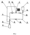
- a pressure system 1 is shown, connected to a storage vessel 2 by means of a drawing-off conduit 3 provided with a closing device 10.
- a return conduit 4 incorporating a compressor 5 is connected at its ends to the drawing-off conduit 3.
- the pressure system 1 is provided with its own closing device 8 and the storage vessel 2 with a closing device 9.
- the closing device 8 of the pressure system 1 For the elimination of the pressure difference between the pressure system 1 and the storage vessel 2 the closing device 8 of the pressure system 1, the closing device 9 of the storage vessel 2 and the closing device 10 are opened. After the pressure difference has been eliminated, the closing device 10 is closed and the compressor 5 is started which, by way of the return conduit 4, sucks-off vapours of the low-boiling medium from the storage vessel 2 and forces them back into the pressure system 1, reducing thereby simultaneously the pressure in the storage vessel 2 and increasing the pressure in the pressure system 1. After a required pressure difference has been obtained, the compressor 5 is stopped and the closing device 10 is again opened.
- the low-boiling medium flows in a liquid state by way of the drawing-off conduit 3 into the storage vessel 2 until again the pressure difference is eliminated, whereafter the compressor 5 is again started, the first closing device 10 closed and the whole cycle repeated until all low-boiling medium is drawn-off.
- the remaining vapours of the low-boiling medium from the pressure system 1 are sucked-off by exchanging the pressure system 1 for the storage vessel 2, the first closing device 10 is closed and the compressor 5 started.
- the closing device 8 of the pressure system 1 and the closing device 9 of the storage vessel 2 remain for the whole time of drawing-off opened.
- Fig.2 shows a pressure system 1 connected to a storage vessel 2 by way of the drawing-off conduit 3 and a retain conduit 4 incorporating a compressor 5 and connected at its ends to the drawing-off conduit 3.
- the pressure system 1 is provided with its own closing device 8 and the storage vessel 2 with its closing device 9.
- the conduit 3 is provided with two closing devices, namely a first closing device 10 and a second closing device 11.
- the storage vessel 2 is by way of a separate conduit 6 incorporating a condenser 7 and a third closing device 12 connected to the pressure outlet of the compressor 5.
- the return conduit 4 is provided with a fourth closing device 13.
- the arrangement according to Fig.2 operates so that for the establishment of the pressure equilibrium between the pressure system 1 and the storage vessel 2 the first closing device 10 and the second closing device 11 are opened. After the pressure difference has been eliminated, the first closing device is closed and the fourth closing device 13 is opened, while the second closing device 11 remains opened.
- the compressor 5 is started which sucks-off over the return conduit 4 vapours of the low-boiling medium from the storage vessel 2 and forces them back into the pressure system 1, creating simultaneously a pressure reduction in the storage vessel 2 and a pressure increase in the pressure system 1.
- the compressor 5 is stopped and the first closing device 10 is again opened; the fourth closing device 13 can either be closed or reamin opened.
- the low-boiling medium flows in liquid state through the drawing-off conduit 3 until again the pressure difference is eliminated, whereafter the compressor 5 is again started, the first closing device 10 is closed, the fourth closing device 13 (if it did not remain opened) is opened and the whole cycle is repeated until all low-boiling medium is drawn off.
- the remaining vapours of the low-boiling medium are sucked-off by opening the first closing device 10, closing the closing devices 11 and 13, starting the compressor 5, opening the third closing device 12 and by way of the condenser 7 the liquefied low-boiling medium is forced into the storage vessel 2.
- Closing devices the function of which is not mentioned in the course of the individual stages, are supposed to be closed, the closing device 8 of the pressure system 1 and the closing device 9 of the storage vessel 2 are in the course of drawing-off of the low-boiling medium opened.
- the drawing-off of the low-boiling medium can also be obtained by opening the third closing device 13 by way of the condenser 7 over the separate conduit 6.
- the compressor 5 is thereby at standstill and the first closing device 10 is closed.
- the arrangement can also be used for instance for pumping off low-boiling media, particularly cooling agents from transport vessels to pressure transport vessels, for pumping over from one vessel to another, for instance in order to regenerate cooling agents where, if needed, the liquid cooling agent is pumped over by way of a regenerating filter either directly, in which case the vessel with the contaminated cooling agent connection to the suction part of the arrangement according to this invention is turned over with its closing device downwards, thus realizing a direct pumping-over of the liquid medium while the arrangement operates as has been described, or in case a distillation of the cooling agent is required, the arrangement is operated at conditions of sucking-off vapours and the vessels with the contaminated cooling agent serves in this case as an improper evaporator, being in its fundamental position, i.e. with the valve upwards.
- the whole arrangement can be very easily be automated by using electrically controlled closing elements, pressure pick-ups and pick-ups of the passage of liquid.
Landscapes
- Engineering & Computer Science (AREA)
- Mechanical Engineering (AREA)
- General Engineering & Computer Science (AREA)
- Physics & Mathematics (AREA)
- Thermal Sciences (AREA)
- Filling Or Discharging Of Gas Storage Vessels (AREA)
- Liquid Developers In Electrophotography (AREA)
- General Preparation And Processing Of Foods (AREA)
- Pharmaceuticals Containing Other Organic And Inorganic Compounds (AREA)
- Pens And Brushes (AREA)
- Vehicle Body Suspensions (AREA)
- Jet Pumps And Other Pumps (AREA)
- Steroid Compounds (AREA)
- Separation By Low-Temperature Treatments (AREA)
- Cookers (AREA)
Abstract
Description
- The invention relates to a method for drawing-off low-boiling medium from a pressure system into a storage vessel, and it also relates to an arrangement for carrying out said method.
- By the term "pressure system" can be understood for instance a cooling circuit of a cooling device, a collector of a liquid cooling medium of a cooling circuit and also any vessel for a low-boiling medium, for instance a transport vessel of a liquid cooling medium, a storage vessel of a low-boiling medium for filling of fire extinguishers and the like. By the expression "low-boiling medium" can be understood fluorinated and chlorinated hydrocarbons used as cooling agents and sold under the name freon, furthermore halogenized hydrocabons used for fire extinguishers, liquefied gases and all other liquids having a low boiling point lower than 80°C at normal barometric pressure.
- In various industrial branches, in business and services, health service, agriculture and households, arrangements are used, the working agent of which consists of a low-boiling medium contained within a pressure system. In many cases said agents are objectionable for hygienic reasons and sometimes also for ecologic reasons. Said media have to be frequently drawn-off from the pressure systems. These media are in many cases discharged into the atmosphere or specially designed pumping devices are used, while residual vapours of the cooling agent which remain after pumping-off the liquid cannot be easily removed. For instance in cases where for some reason the cooling agent from condensation cooling units and cooling circuits has to be removed or pumped-off, this agent is mostly discharged into the surrounding atmosphere. It is a known fact that fluorinated and chlorinated hydrocarbons which are used as cooling agents affect the protective ozone envelope of the atmosphere, which substantially influences the global environmental conditions. Therefore ways of preventing leakage of said cooling agents into the atmosphere are looked for. In known arrangements serving for the drawing-off of cooling agents as for instance described in DE-OS No.3 001 224 this problem of drawing-off vapours of cooling agents from cooling circuits and condensation units has been tackled, however with low pumping effect and unfavourable undercooling of the cooling unit and due to a realized distillation of the cooling agent a substantial part of contaminations contained in the liquid cooling agent have remained in the circuit. This concerns particularly products from built-in electric motors which have been damaged due to short circuiting, of semi-hermetic and hermetic compressors, contaminated oil and other contaminations which have at prevailing conditions a higher boiling temperature than the used cooling agent. As practically the whole cooling agent is pumped-off by way of a suction filter and a compressor which is mostly of a hermetic design, the life time of the compressor is reduced, the consumption of electric power is increased and a frequent exchange of the suction filter is required. Known arrangements of this kind have usually an overall weight of around 50 kg, are costly, and manipulation with them is difficult and physically demanding.
- International application WO 89/02567 relates to a method for rapid emptying of refrigerants from large-scale refrigerant and heat pump units by a pressure difference generated by a compressor, in which, however, the pressure difference is kept constant until the pressure system is emptied.
- Known prior art includes also DE 3616591 which discloses the transport of a refrigerant from a cooling circuit, i.e. from a pressure system, into a storage vessel for the refrigerant. In order to prevent uncontrolled leakage of the refrigerant into the ambient atmosphere during this action, the device is so arranged that the refrigerant in the form of a vapour is drawn-off from the pressure system and liquefied refrigerant is fed into the storage vessel. The drawing-off device for carrying out this method comprises a compressor and an air-cooled condenser connected in series.
- The purpose of the device disclosed is merely the drawing-off of the refrigerant vapours and their additional liquefying. However, in the cooling circuits of the condensation type, i.e. containing a condenser, a considerable amount of the refrigerant in the form of a liquid is present. The drawing-off rate is limited by the vaporisation rate in the pressure system. It is at the same time impossible and prohibited to increase this vaporisation rate by heating this pressure system so that the total drawing-off rate is limited by the natural vaporization of the refrigerant. In addition the described device does not allow the transport of liquid refrigerant from one storage vessel into the other.
- In contrast to the last mentioned prior art a method and an arrangement according to the invention allow the transport of the liquid refrigerant and the refrigerant vapours independently of the vaporization process in the pressure system.
- The invention provides a method for drawing-off low boiling media from a pressure system into a storage vessel, comprising the following steps:
- a) periodically generating a pressure difference between the pressure system and the storage vessel by sucking-off vapours from the storage vessel, compressing the vapours and feeding the same into the pressure system, thereby reducing the pressure in the storage vessel and increasing the pressure above the liquid level in the pressure system; and
- b) drawing-off, after each pressure difference generation, the low-boiling medium from the pressure system and emptying it into the storage vessel by means reducing the pressure difference.
- The invention also provides an arrangement for carrying out the method comprising a drawing-off conduit and by a return conduit both having a first end for connection to a pressure system and a second end for connection to a storage vessel, a compressor in the return conduit having its suction side connected with the second end and its discharge side connected with the first end and a first flow control device in the drawing-off conduit, wherein the first ends of both conduits are formed in a first single duct for communication with the pressure system and the second ends of both conduits are formed in a second single duct for communication with the storage vessel.
- According to this invention, after obtaining a pressure equilibrium between the pressure system and the storage vessel from which pressure system the cooling agent has to be pumped off into the storage vessel, the pressure in the storage vessel is reduced and the pressure in the pressure system is increased. Vapours from the storage vessel are sucked-off into the pressure system and due to a now established pressure difference, the low-boiling medium is drawn-off from the pressure system into the storage vessel.
- The result of this action is that due to the obtained high pressure difference between the pressure system and the storage vessel a relatively high speed increase of the pumped-off medium is achieved. This effect is obtained by introduction of a drawing-off conduit connecting the pressure system with the storage vessel and furthermore of a return conduit, to which a compressor is connected. The major part of the low-boiling medium is pumped-off by way of the drawing-off conduit in liquid state beyond the compressor, which is therefore exposed only to a slight degree to vapours of the low-boiling medium and this prolongs the life of the compressor. In addition in the course of this process of drawing-off of the liquid no unwelcome undercooling of the pumped-off pressure system is experienced, its temperature is on the contrary increased and the storage vessel is undercooled. Another advantage is that the pumped-off low-boiling liquid takes along the major part of unwelcome materials (contaminations) which are dissolved in the liquid phase. By the introduction of a condenser into a separate conduit the drawing-off of residua of the low-boiling medium as vapours can be achieved.
- The arrangement for carrying out the method for drawing-off according to this invention achieves a speed of drawing-off the low-boiling medium five times higher than arrangements according to the present state of the art. The weight of the arrangement according to the invention is thereby less than half of the known arrangements, so that it is easily transportable and can be used directly on site, for instance at the damaged cooling unit.
- For a prototype of an arrangement operating according to this invention used for the pumping off of a liquid cooling agent known under the commercial name "freon R12" from a pressure system in the form of a collector of a condensation cooling unit of a content of 15 kg to a storage vessel of a utilizable content of 7 kg, a pumping-off rate of 70 kg of cooling agent per hour has been achieved. The weight of the arrangement was only 21 kg. Arrangements used for the same purpose which achieve a maximum pumping-off rate of 10 kg per hour have weight of about 50 kg.
- Three embodiments of an arrangement according to the invention will now be described, by way of example, with reference to the accompanying diagrammatic drawings, in which:
- Fig.1 is a circuit arrangement showing the connection of the pressure system and the storage vessel by way of a drawing-off conduit and a return conduit, and
- Fig.2 is an arrangement having a separate conduit with a condenser.
- With reference to Fig.1 a
pressure system 1 is shown, connected to astorage vessel 2 by means of a drawing-offconduit 3 provided with aclosing device 10. Areturn conduit 4 incorporating acompressor 5 is connected at its ends to the drawing-offconduit 3. Thepressure system 1 is provided with itsown closing device 8 and thestorage vessel 2 with aclosing device 9. - For the elimination of the pressure difference between the
pressure system 1 and thestorage vessel 2 theclosing device 8 of thepressure system 1, theclosing device 9 of thestorage vessel 2 and theclosing device 10 are opened. After the pressure difference has been eliminated, theclosing device 10 is closed and thecompressor 5 is started which, by way of thereturn conduit 4, sucks-off vapours of the low-boiling medium from thestorage vessel 2 and forces them back into thepressure system 1, reducing thereby simultaneously the pressure in thestorage vessel 2 and increasing the pressure in thepressure system 1. After a required pressure difference has been obtained, thecompressor 5 is stopped and theclosing device 10 is again opened. Due to the established pressure difference the low-boiling medium flows in a liquid state by way of the drawing-off conduit 3 into thestorage vessel 2 until again the pressure difference is eliminated, whereafter thecompressor 5 is again started, thefirst closing device 10 closed and the whole cycle repeated until all low-boiling medium is drawn-off. The remaining vapours of the low-boiling medium from thepressure system 1 are sucked-off by exchanging thepressure system 1 for thestorage vessel 2, thefirst closing device 10 is closed and thecompressor 5 started. Theclosing device 8 of thepressure system 1 and theclosing device 9 of thestorage vessel 2 remain for the whole time of drawing-off opened. - Fig.2 shows a
pressure system 1 connected to astorage vessel 2 by way of the drawing-offconduit 3 and aretain conduit 4 incorporating acompressor 5 and connected at its ends to the drawing-off conduit 3. Thepressure system 1 is provided with itsown closing device 8 and thestorage vessel 2 with itsclosing device 9. In this embodiment theconduit 3 is provided with two closing devices, namely afirst closing device 10 and asecond closing device 11. Thestorage vessel 2 is by way of aseparate conduit 6 incorporating acondenser 7 and athird closing device 12 connected to the pressure outlet of thecompressor 5. Thereturn conduit 4 is provided with afourth closing device 13. - The arrangement according to Fig.2 operates so that for the establishment of the pressure equilibrium between the
pressure system 1 and thestorage vessel 2 thefirst closing device 10 and thesecond closing device 11 are opened. After the pressure difference has been eliminated, the first closing device is closed and thefourth closing device 13 is opened, while thesecond closing device 11 remains opened. Thecompressor 5 is started which sucks-off over thereturn conduit 4 vapours of the low-boiling medium from thestorage vessel 2 and forces them back into thepressure system 1, creating simultaneously a pressure reduction in thestorage vessel 2 and a pressure increase in thepressure system 1. After the required pressure difference has been obtained, thecompressor 5 is stopped and thefirst closing device 10 is again opened; thefourth closing device 13 can either be closed or reamin opened. Due to the established pressure difference the low-boiling medium flows in liquid state through the drawing-offconduit 3 until again the pressure difference is eliminated, whereafter thecompressor 5 is again started, thefirst closing device 10 is closed, the fourth closing device 13 (if it did not remain opened) is opened and the whole cycle is repeated until all low-boiling medium is drawn off. The remaining vapours of the low-boiling medium are sucked-off by opening thefirst closing device 10, closing theclosing devices compressor 5, opening thethird closing device 12 and by way of thecondenser 7 the liquefied low-boiling medium is forced into thestorage vessel 2. Closing devices, the function of which is not mentioned in the course of the individual stages, are supposed to be closed, theclosing device 8 of thepressure system 1 and theclosing device 9 of thestorage vessel 2 are in the course of drawing-off of the low-boiling medium opened. The drawing-off of the low-boiling medium can also be obtained by opening thethird closing device 13 by way of thecondenser 7 over theseparate conduit 6. Thecompressor 5 is thereby at standstill and thefirst closing device 10 is closed. - The arrangement can also be used for instance for pumping off low-boiling media, particularly cooling agents from transport vessels to pressure transport vessels, for pumping over from one vessel to another, for instance in order to regenerate cooling agents where, if needed, the liquid cooling agent is pumped over by way of a regenerating filter either directly, in which case the vessel with the contaminated cooling agent connection to the suction part of the arrangement according to this invention is turned over with its closing device downwards, thus realizing a direct pumping-over of the liquid medium while the arrangement operates as has been described, or in case a distillation of the cooling agent is required, the arrangement is operated at conditions of sucking-off vapours and the vessels with the contaminated cooling agent serves in this case as an improper evaporator, being in its fundamental position, i.e. with the valve upwards. The whole arrangement can be very easily be automated by using electrically controlled closing elements, pressure pick-ups and pick-ups of the passage of liquid.
Claims (4)
- Method for drawing-off low boiling media from a pressure system into a storage vessel, comprising the following steps:a) periodically generating a pressure difference between the pressure system and the storage vessel by sucking-off vapours from the storage vessel, compressing the vapours and feeding the same into the pressure system, thereby reducing the pressure in the storage vessel and increasing the pressure above the liquid level in the pressure system; andb) drawing-off, after each pressure difference generation, the low-boiling medium from the pressure system and emptying it into the storage vessel by means reducing the pressure difference.
- Arrangement for carrying out the method of Claim 1, comprising a drawing-off conduit (3) and a return conduit (4) both having a first end for connection to a pressure system (1) and a second end for connection to a storage vessel (2), a compressor (5) in the return conduit (4) having its suction side connected with the second end and its discharge side connected with the first end and a first flow control device (10) in the drawing-off conduit (3), wherein the first ends of both conduits (3,4) are formed in a first single duct for communication with the pressure system (1) and the second ends of both conduits (3,4) are formed in a second single duct for communication with the storage vessel (2).
- Arrangement according to Claim 2, wherein the pressure system (1) is provided with a closing device (8) and the storage vessel (2) is provided with a closing device (9), a second flow control device (11) is arranged between the first flow control device (10) and the closing device (9) of the storage vessel (2), and a separate conduit (6) incorporating a condenser (7) and a third flow control device (12) is branched off from the second single duct between the second flow control device (11) and the closing device (9) of the storage vessel (2) for communication with the return conduit (4) at the discharge side of the compressor (5).
- Arrangement according to Claim 3, comprising a further flow control device (13) incorporated into the return conduit (4) between the closing device (8) of the pressure system (1) and the point of communication of the separate conduit (6) with the return conduit (4).
Priority Applications (1)
| Application Number | Priority Date | Filing Date | Title |
|---|---|---|---|
| AT88308379T ATE82382T1 (en) | 1987-09-14 | 1988-09-09 | PROCESS FOR FILLING LOW-BOILING MEDIA FROM A PRESSURE SYSTEM AND PLANT FOR CARRYING OUT THIS PROCESS. |
Applications Claiming Priority (2)
| Application Number | Priority Date | Filing Date | Title |
|---|---|---|---|
| CS6658/87 | 1987-09-14 | ||
| CS876658A CS266405B1 (en) | 1987-09-14 | 1987-09-14 | Method of low-boiling medium pumping from pressure systems and device for carrying out the method |
Publications (2)
| Publication Number | Publication Date |
|---|---|
| EP0308149A1 EP0308149A1 (en) | 1989-03-22 |
| EP0308149B1 true EP0308149B1 (en) | 1992-11-11 |
Family
ID=5414156
Family Applications (1)
| Application Number | Title | Priority Date | Filing Date |
|---|---|---|---|
| EP88308379A Expired - Lifetime EP0308149B1 (en) | 1987-09-14 | 1988-09-09 | A method for drawing-off low boiling media from a pressure system and arrangement for carrying out the method |
Country Status (10)
| Country | Link |
|---|---|
| US (1) | US4898006A (en) |
| EP (1) | EP0308149B1 (en) |
| JP (1) | JPS6484063A (en) |
| AT (1) | ATE82382T1 (en) |
| AU (1) | AU2190588A (en) |
| BR (1) | BR8804715A (en) |
| CS (1) | CS266405B1 (en) |
| DE (1) | DE3875891T2 (en) |
| FI (1) | FI884198A7 (en) |
| NO (1) | NO884067L (en) |
Families Citing this family (8)
| Publication number | Priority date | Publication date | Assignee | Title |
|---|---|---|---|---|
| EP0394187B1 (en) * | 1989-04-17 | 1992-07-15 | GebràDer Sulzer Aktiengesellschaft | Method for the recovery of nlg |
| WO1992016260A1 (en) * | 1991-03-21 | 1992-10-01 | Team Aer Lingus | Halogenated hydrocarbon recycling machine |
| US5263326A (en) * | 1991-03-21 | 1993-11-23 | Team Aer Lingus | Halogenated hydrocarbon recycling machine |
| DE10201274A1 (en) * | 2002-01-15 | 2003-07-24 | Linde Ag | Method for controlling the pressure in a cryogenic liquid stored in a storage container |
| RU2641416C1 (en) * | 2017-02-10 | 2018-01-17 | Общество с ограниченной ответственностью "Газхолодтехника" | Method of production of compromised natural gas at the gas distribution station and booster compressor for the realisation of such method |
| GB2564879A (en) * | 2017-07-25 | 2019-01-30 | Linde Ag | Liquiefying a gaseous medium |
| DE102017120384B4 (en) | 2017-09-05 | 2023-03-16 | Fft Produktionssysteme Gmbh & Co. Kg | Filling device for filling air conditioning systems with CO2 |
| KR102761703B1 (en) * | 2022-10-27 | 2025-02-03 | 세메스 주식회사 | Substrate treating apparatus |
Family Cites Families (4)
| Publication number | Priority date | Publication date | Assignee | Title |
|---|---|---|---|---|
| US4249387A (en) * | 1979-06-27 | 1981-02-10 | Phillips Petroleum Company | Refrigeration of liquefied petroleum gas storage with retention of light ends |
| SE418769B (en) * | 1979-09-17 | 1981-06-22 | Langgard Sixten | DEVICE FOR DRAINING REFRIGERANT FROM REFRIGERATOR AND HEATER |
| CH644442A5 (en) * | 1980-04-29 | 1984-07-31 | Sulzer Ag | DEVICE FOR PRODUCING COLD. |
| DE3616591A1 (en) * | 1986-05-16 | 1987-11-19 | Weiss Umwelttechnik Gmbh | METHOD AND DEVICE FOR CONVERTING REFRIGERANTS FROM A REFRIGERANT CIRCUIT INTO A REFRIGERANT STORAGE |
-
1987
- 1987-09-14 CS CS876658A patent/CS266405B1/en unknown
-
1988
- 1988-09-06 AU AU21905/88A patent/AU2190588A/en not_active Abandoned
- 1988-09-06 JP JP63221500A patent/JPS6484063A/en active Pending
- 1988-09-09 AT AT88308379T patent/ATE82382T1/en active
- 1988-09-09 DE DE8888308379T patent/DE3875891T2/en not_active Expired - Fee Related
- 1988-09-09 EP EP88308379A patent/EP0308149B1/en not_active Expired - Lifetime
- 1988-09-13 FI FI884198A patent/FI884198A7/en not_active Application Discontinuation
- 1988-09-13 BR BR8804715A patent/BR8804715A/en unknown
- 1988-09-13 NO NO88884067A patent/NO884067L/en unknown
- 1988-10-12 US US07/256,833 patent/US4898006A/en not_active Expired - Fee Related
Non-Patent Citations (1)
| Title |
|---|
| WO 89/02567 * |
Also Published As
| Publication number | Publication date |
|---|---|
| EP0308149A1 (en) | 1989-03-22 |
| FI884198L (en) | 1989-03-15 |
| FI884198A7 (en) | 1989-03-15 |
| NO884067L (en) | 1989-03-15 |
| CS665887A1 (en) | 1989-02-10 |
| DE3875891T2 (en) | 1993-05-27 |
| ATE82382T1 (en) | 1992-11-15 |
| NO884067D0 (en) | 1988-09-13 |
| BR8804715A (en) | 1989-04-18 |
| DE3875891D1 (en) | 1992-12-17 |
| JPS6484063A (en) | 1989-03-29 |
| CS266405B1 (en) | 1990-01-12 |
| AU2190588A (en) | 1989-03-16 |
| US4898006A (en) | 1990-02-06 |
| FI884198A0 (en) | 1988-09-13 |
Similar Documents
| Publication | Publication Date | Title |
|---|---|---|
| US5548966A (en) | Refrigerant recovery system | |
| US4363222A (en) | Environmental protection refrigerant disposal and charging system | |
| US4261178A (en) | Environmental protection refrigeration disposal and charging system | |
| US4766733A (en) | Refrigerant reclamation and charging unit | |
| US4809515A (en) | Open cycle cooled refrigerant recovery apparatus | |
| US5875638A (en) | Refrigerant recovery system | |
| KR102944209B1 (en) | Device and method for delivering cryogenic fluid | |
| US4010779A (en) | Apparatus for recovery of vapor | |
| US5230224A (en) | Refrigerant recovery system | |
| US5291743A (en) | Refrigerant reclaim with automatic air purge | |
| ES2240248T3 (en) | FILLING DEVICE FOR INSTALLATIONS OF AIR CONDITIONING OF MOTOR VEHICLES. | |
| US6029472A (en) | Refrigerant recycle and reclaim system | |
| US4903496A (en) | Plant and method for periodic charging and discharging of a gas reservoir | |
| US4350018A (en) | Gas recovery system | |
| CA1221088A (en) | Process for the transfer of refrigeration | |
| US5189881A (en) | Refrigerant recovery apparatus and method | |
| US6029473A (en) | Process and installation for filling a reservoir under pressure | |
| EP0308149A1 (en) | A method for drawing-off low boiling media from a pressure system and arrangement for carrying out the method | |
| CA2090276C (en) | Oil purifying device for use with a refrigeration system | |
| CA1269855A (en) | Helium dilution refrigeration system | |
| US5375425A (en) | Collection method for gaseous or liquid phase materials | |
| CN2206933Y (en) | Low-pressure refrigerant retrieve purify device | |
| CN101017043A (en) | Multifunctional reclaiming machine | |
| US3123983A (en) | Means for removal of liquefied gas | |
| JP3151460B2 (en) | Gas recovery and filling equipment |
Legal Events
| Date | Code | Title | Description |
|---|---|---|---|
| PUAI | Public reference made under article 153(3) epc to a published international application that has entered the european phase |
Free format text: ORIGINAL CODE: 0009012 |
|
| AK | Designated contracting states |
Kind code of ref document: A1 Designated state(s): AT BE CH DE ES FR GB GR IT LI LU NL SE |
|
| 17P | Request for examination filed |
Effective date: 19890811 |
|
| 17Q | First examination report despatched |
Effective date: 19900409 |
|
| GRAA | (expected) grant |
Free format text: ORIGINAL CODE: 0009210 |
|
| AK | Designated contracting states |
Kind code of ref document: B1 Designated state(s): AT BE CH DE ES FR GB GR IT LI LU NL SE |
|
| PG25 | Lapsed in a contracting state [announced via postgrant information from national office to epo] |
Ref country code: IT Free format text: LAPSE BECAUSE OF FAILURE TO SUBMIT A TRANSLATION OF THE DESCRIPTION OR TO PAY THE FEE WITHIN THE PRESCRIBED TIME-LIMIT;WARNING: LAPSES OF ITALIAN PATENTS WITH EFFECTIVE DATE BEFORE 2007 MAY HAVE OCCURRED AT ANY TIME BEFORE 2007. THE CORRECT EFFECTIVE DATE MAY BE DIFFERENT FROM THE ONE RECORDED. Effective date: 19921111 Ref country code: NL Effective date: 19921111 Ref country code: LI Effective date: 19921111 Ref country code: SE Effective date: 19921111 Ref country code: GR Free format text: LAPSE BECAUSE OF FAILURE TO SUBMIT A TRANSLATION OF THE DESCRIPTION OR TO PAY THE FEE WITHIN THE PRESCRIBED TIME-LIMIT Effective date: 19921111 Ref country code: BE Effective date: 19921111 Ref country code: CH Effective date: 19921111 Ref country code: ES Free format text: THE PATENT HAS BEEN ANNULLED BY A DECISION OF A NATIONAL AUTHORITY Effective date: 19921111 Ref country code: FR Effective date: 19921111 Ref country code: AT Effective date: 19921111 |
|
| REF | Corresponds to: |
Ref document number: 82382 Country of ref document: AT Date of ref document: 19921115 Kind code of ref document: T |
|
| REF | Corresponds to: |
Ref document number: 3875891 Country of ref document: DE Date of ref document: 19921217 |
|
| REG | Reference to a national code |
Ref country code: CH Ref legal event code: PL |
|
| EN | Fr: translation not filed | ||
| NLV1 | Nl: lapsed or annulled due to failure to fulfill the requirements of art. 29p and 29m of the patents act | ||
| PG25 | Lapsed in a contracting state [announced via postgrant information from national office to epo] |
Ref country code: GB Effective date: 19930909 |
|
| PLBE | No opposition filed within time limit |
Free format text: ORIGINAL CODE: 0009261 |
|
| STAA | Information on the status of an ep patent application or granted ep patent |
Free format text: STATUS: NO OPPOSITION FILED WITHIN TIME LIMIT |
|
| PG25 | Lapsed in a contracting state [announced via postgrant information from national office to epo] |
Ref country code: LU Free format text: LAPSE BECAUSE OF NON-PAYMENT OF DUE FEES Effective date: 19930930 |
|
| 26N | No opposition filed | ||
| GBPC | Gb: european patent ceased through non-payment of renewal fee |
Effective date: 19930909 |
|
| PGFP | Annual fee paid to national office [announced via postgrant information from national office to epo] |
Ref country code: DE Payment date: 19950918 Year of fee payment: 8 |
|
| PG25 | Lapsed in a contracting state [announced via postgrant information from national office to epo] |
Ref country code: DE Effective date: 19970603 |