EP0308006A1 - Transport device for carriers - Google Patents
Transport device for carriers Download PDFInfo
- Publication number
- EP0308006A1 EP0308006A1 EP88201917A EP88201917A EP0308006A1 EP 0308006 A1 EP0308006 A1 EP 0308006A1 EP 88201917 A EP88201917 A EP 88201917A EP 88201917 A EP88201917 A EP 88201917A EP 0308006 A1 EP0308006 A1 EP 0308006A1
- Authority
- EP
- European Patent Office
- Prior art keywords
- transport
- transport device
- parallel
- carrier
- rotation
- Prior art date
- Legal status (The legal status is an assumption and is not a legal conclusion. Google has not performed a legal analysis and makes no representation as to the accuracy of the status listed.)
- Granted
Links
- 239000000969 carrier Substances 0.000 title claims abstract description 17
- 230000008878 coupling Effects 0.000 claims description 15
- 238000010168 coupling process Methods 0.000 claims description 15
- 238000005859 coupling reaction Methods 0.000 claims description 15
- 238000006073 displacement reaction Methods 0.000 claims description 9
- 230000032258 transport Effects 0.000 description 49
- 230000007246 mechanism Effects 0.000 description 14
- 238000010276 construction Methods 0.000 description 6
- 230000005540 biological transmission Effects 0.000 description 3
- 238000004519 manufacturing process Methods 0.000 description 2
- 230000006978 adaptation Effects 0.000 description 1
- 238000007599 discharging Methods 0.000 description 1
- 230000004048 modification Effects 0.000 description 1
- 238000012986 modification Methods 0.000 description 1
- 238000004904 shortening Methods 0.000 description 1
Images


Classifications
-
- H—ELECTRICITY
- H05—ELECTRIC TECHNIQUES NOT OTHERWISE PROVIDED FOR
- H05K—PRINTED CIRCUITS; CASINGS OR CONSTRUCTIONAL DETAILS OF ELECTRIC APPARATUS; MANUFACTURE OF ASSEMBLAGES OF ELECTRICAL COMPONENTS
- H05K13/00—Apparatus or processes specially adapted for manufacturing or adjusting assemblages of electric components
- H05K13/0061—Tools for holding the circuit boards during processing; handling transport of printed circuit boards
-
- B—PERFORMING OPERATIONS; TRANSPORTING
- B65—CONVEYING; PACKING; STORING; HANDLING THIN OR FILAMENTARY MATERIAL
- B65G—TRANSPORT OR STORAGE DEVICES, e.g. CONVEYORS FOR LOADING OR TIPPING, SHOP CONVEYOR SYSTEMS OR PNEUMATIC TUBE CONVEYORS
- B65G25/00—Conveyors comprising a cyclically-moving, e.g. reciprocating, carrier or impeller which is disengaged from the load during the return part of its movement
- B65G25/04—Conveyors comprising a cyclically-moving, e.g. reciprocating, carrier or impeller which is disengaged from the load during the return part of its movement the carrier or impeller having identical forward and return paths of movement, e.g. reciprocating conveyors
- B65G25/06—Conveyors comprising a cyclically-moving, e.g. reciprocating, carrier or impeller which is disengaged from the load during the return part of its movement the carrier or impeller having identical forward and return paths of movement, e.g. reciprocating conveyors having carriers, e.g. belts
-
- Y—GENERAL TAGGING OF NEW TECHNOLOGICAL DEVELOPMENTS; GENERAL TAGGING OF CROSS-SECTIONAL TECHNOLOGIES SPANNING OVER SEVERAL SECTIONS OF THE IPC; TECHNICAL SUBJECTS COVERED BY FORMER USPC CROSS-REFERENCE ART COLLECTIONS [XRACs] AND DIGESTS
- Y10—TECHNICAL SUBJECTS COVERED BY FORMER USPC
- Y10T—TECHNICAL SUBJECTS COVERED BY FORMER US CLASSIFICATION
- Y10T29/00—Metal working
- Y10T29/53—Means to assemble or disassemble
- Y10T29/5313—Means to assemble electrical device
- Y10T29/53174—Means to fasten electrical component to wiring board, base, or substrate
- Y10T29/53183—Multilead component
-
- Y—GENERAL TAGGING OF NEW TECHNOLOGICAL DEVELOPMENTS; GENERAL TAGGING OF CROSS-SECTIONAL TECHNOLOGIES SPANNING OVER SEVERAL SECTIONS OF THE IPC; TECHNICAL SUBJECTS COVERED BY FORMER USPC CROSS-REFERENCE ART COLLECTIONS [XRACs] AND DIGESTS
- Y10—TECHNICAL SUBJECTS COVERED BY FORMER USPC
- Y10T—TECHNICAL SUBJECTS COVERED BY FORMER US CLASSIFICATION
- Y10T29/00—Metal working
- Y10T29/53—Means to assemble or disassemble
- Y10T29/5313—Means to assemble electrical device
- Y10T29/53261—Means to align and advance work part
Abstract
Description
- The invention relates to a transport device for carriers comprising a follower element which is movable in a reciprocating manner in a first transport direction and can be coupled by means of centering members with a carrier, this follower element being displaceable in a second transport direction at right angles to the first transport direction, while the follower element is coupled to and decoupled from a carrier by a relative displacement of carrier and follower element in a direction at right angles to a plane passing through the first and second transport directions.
- The transport device is more particularly intended for plate-shaped carriers, such as, for example, printed circuit boards. It should be noted that the term "plate-shaped carriers" used hereinafter also includes within the scope of the invention carriers of different shapes, such as for example, a box or a frame of an apparatus having parallel and straight edges located in a flat plane.
- In a transport device mentioned in the opening paragraph and known from US-PS 4,202,092, a follower element provided with arms with centering pins is not only displaceable in a direction parallel to the first transport direction, but is also rotatable about an axis of rotation parallel to the first transport direction. A disadvantage of such a transport device is that the positioning accuracy of the centering pins is comparatively low because it is influenced to a considerable extent by inaccuracies in the guidance for the rotary movement of the follower element about the axis of rotation parallel to the first transport direction.
- The invention has for its object to provide a transport device having a comparatively high positioning accuracy of the centering members for the plate-shaped carriers.
- The transport device according to the invention is for this purpose characterized in that the transport device is provided with a guide for the carrier, which is pivotable about an axis of rotation parallel to the first transport direction, extends in the first transport direction and is displaceable, when pivoted about the said axis of rotation, together with the carrier in a direction at right angles to the plane through the first and second transport directions.
- The invention is based on the recognition of the fact that the plate-shaped carriers can be centered by means of centering members very accurately if the construction for the guidance or displacement of the follower element in the first transport direction is decoupled from the construction of another movement mechanism, i.e. more particularly the movement mechanism, by which the relative movement of carrier and centering members is obtained.
- It should be noted that US-PS 4,524,860 discloses a transport device comprising an arm mechanism for coupling and decoupling a plate-shaped carrier to and from centering members, this carrier being displaced parallel to the first transport direction by means of a separate transporter. Although that case does involve a decoupling of the translatory movement of the transporter and the centering and decentering movement of the arm mechanism, the possibility of translation of the arm mechanism parallel to the first transport direction nevertheless again leads to a comparatively low positioning accuracy.
- Further, a transport device of the indexing type is known from US-PS 2,851,145, in which at discrete areas along an assembly line transmission mechanism are arranged. The construction of these transmission mechanisms is not coupled to the construction for the translatory movement of the plate-shaped carriers. On the contrary, the centering members can be coupled and decoupled only at the locations of the transmission mechanisms so that there is a considerable limitation with respect to the choice of the place of the working stations, the choice of the kind and the size of the product, etc. A so-called freely programmable assembly line, which can be readily adapted in cases of product modification, cannot be obtained with the transport devices of the indexing type.
- A particular embodiment of the transport device according to the invention, which permits a comparatively large variation of the length of the plate-shaped carriers in the first transport direction, is further characterized in that a carrier is guided with a first edge in a first guide pivotable about the axis of rotation and is guided with a second edge parallel to the first edge in a second guide, which is pivotable together with the first guide about the axis of rotation and is parallel to the first guide.
- A further embodiment of the transport device with a large freedom of choice with respect to the centring holes in the plate-shaped carrier, is characterized in that the folllower element is provided with a row of detachably secured centering pins arranged regularly in the first transport direction.
- A further embodiment of the transport device which vacilitates the adaptation of the production capacity due to its modular construction is characterized in that the transport device comprises at least two positioning modules, one positioning module having an X carriage displaceable parallel to the first transport direction, which is displaceable together with a Y carriage in a direction parallel to the second transport direction at right angles to the first transport direction, while the X carriages and Y carriages of different positioning modules are connected to each other by a first coupling and second coupling, respectively.
- The invention will be described more fully with reference to the drawings, in which:
- Fig. 1 shows diagrammatically in plan view an assembly line with a transport device according to the invention,
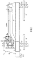
- Fig. 2 shows in side elevation a part of a first embodiment of the transport device,
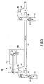
- Fig. 3 is a front elevation of a lifting mechanism used in the transport device shown in Fig.2,
- Fig. 4 shows a plan view, a side elevation and a bottom view of a centering member used in the transport device shown in Fig.2,
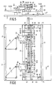
- Fig. 5 is a side elevation of a part of a second embodiment of the transport device,
- Fig. 6 is a plan view of the transport device shown in Fig. 5,
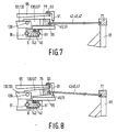
- Fig. 7 is a sectional view of the transport device shown in Fig.5 having a plate-shaped carrier in the centered position,
- Fig. 8 shows in sectional view the transport device shown in Fig.5 having a plate-shaped carrier in the pivoted position.
- The assembly line shown in Fig.1 is intended for mounting component parts on plate-shaped carriers, for example for arranging electronic components on a printed circuit board. In the assembly line shown, there are three working stations A, B and C beside a transport device 1. In a manner known per se, simple or multiple placement robots are arranged in the working stations A, B and C. The transport device 1 comprises three
positioning modules module 3 ofwhich serves at the same time as driving module. Each positioning module is provided with anX carriage 9 displaceable parallel to the X direction and aY carriage 11 displaceable parallel to the Y direction. TheX carriages 9 supported by theY carriages 11 can be displaced parallel both to the X and to the Y direction. In the latter case, the Y carriages also move parallel to the Y direction. TheX carriages 9 of thepositioning modules rod 13, while theX carriages 9 of thepositioning modules rod 15. Therods Y carriages 11 of thepositioning modules positioning modules rods rods portion 21, which is pivotably secured totriangular links rods Y carriages 11. Thelinks pivots pinion 35, which is driven by an electric motor (not visible) and is in engagement with atoothed rim 37. Thepinion 35 is situated on the output shaft of an electric motor secured on theY carriage 11 of thedriving module 3 and thetoothed rim 37 is secured on theX carriage 9 of the same module. The drive in the Y direction is obtained by means of a pinion 39, which is driven by a fixed electric motor (not shown) and is in engagement with agreat wheel 41, of which the axis of rotation coincides with the pivot shaft of thelink 23. TheX carriages 9 of thepositioning modules circuit boards X carriage 9 in the X direction is equal to the length of a printed circuit board plus the relative distance of two successive printed circuit boards, both in the same positioning module and in successive positioning modules. This so-called pitch distance between printed circuit boards is therefore constant. This means in other words that the distance in the X-direction between two successive printed circuit boards in the same positioning module is equal to the distance between the last printed circuit board in one positioning module and the first printed circuit board in the succeeding positioning module. - The distance between different modules may also be so large that the pitch distance between the printed circuit boards no longer corresponds to the overall periodical displacement the X carriages have to perform to transport a printed circuit board from one module to the other. In this case, there is always a number of printed circuit boards situated between the positioning modules.
- On an
X carriage 9 the position of a printed circuit board is determined by two centering members in the form of centeringpins X carriage 9 is constituted by a profile which is triangular in a sectional view transverse to the X direction and to which anelongate lath 53 is secured, which is provided with twopin holders 55. A centering pin is mounted in each of thepin holders 55. TheY carriage 11 comprises acylinder 57, which extends parallel to the X direction and is provided with two blocks 59 (of which only one block is shown in Fig.2). In each of the twoblocks 59 are rotatably arranged four runningrollers 61, along which theX carriage 9 is guided. To thecylinder 57 are secured two arms 63 (only one of which is shown in Fig.2) which are at right angles to the X direction and which are each provided with asupport 65. TheY carriage 11 is guided parallel to the Y direction by means of four pairs ofrunning rollers 67 along twoguides 69. Anarm 73 rotatable about an axis ofrotation 71 is journalled in each of thesupports 65. On thearms 73 are secured twoguides - The
guides axis rotation 71 of thearms 73. The mechanism for rotation of thearms 73 and hence the pivoting of theguides rotation 71 will be described more fully hereinafter with reference to Fig.3. Thepin holder 55 is provided with aflexible tongue 79, which is pressed by means of ascrew 81 against thelath 53 so that a clamping connection is formed between the arm and the lath. The centeringpins pin holder 55 is provided with aslot 83 and with two oppositely arrangedcylindrical engagement surfaces pins screw 89 in a manner known per se. Opposite to the centeringpins pin holders 55 are arrangedlocking pins 91, which are secured to anelongate support 93. Thesupport 93 is connected byrods 95 to theblocks 59. Preferably, alath 53 and asupport 93 individual for each positioning module are used. This also applies to theguides lath 53, asupport 93 and guides 75 and 77 common to all the positioning modules. In the embodiment shown in Fig.2, alternatively an X carriage common to all the positioning modules may be used. Thecouplings 13 in the form of rods are then replaced by the aforementioned profile of triangular cross-section, which extends throughout the length of the assembly line. - After termination of the operations on the printed
circuit boards circuit board 97 being in a waiting position has to be transferred to thefirst positioning module 3, while after transport over the pitch distance a printedcircuit board 99 at the end of the assembly line has to be transferred to a supply of finished products. This is possible, for example, by lengthening, thelath 53 withpin holders 55 beyond the first and the last positioning modules and by using the displacement over the pitch distance for supplying and discharging printed circuit boards to and from the said modules. Subsequently, by X-Y displacements within a positioning module essentially any part of the printed circuit board can be brought underneath, for example, a component placement mechanism of the working station. Before a new printed circuit board is transported to a working station, the combination ofX carriages 9,lath 53 andpin holder 55 acting as a follower element and coupled with the printed circuit boards must be decoupled and must be displaced over a pitch distance in the negative X direction. For this purpose, theguides arm 73 are pivoted about the axis ofrotation 71 by means of alifting mechanism 101 indicated by dotted lines in Fig. 2 and shown in detail in Fig. 3.Pivot shafts blocks 59 of Fig. 2. Thepivot shafts rod 111. Therod 111 extending parallel to the X direction may be common to thelifting mechanism 101 of all the positioning modules. Preferably, however, use is made of anindividual rod 111 for each positioning module. When therods 111 of the various modules are coupled to each other, onelifting mechanism 101 for all rods is sufficient. Arod 113 is pivotably secured to thelink 107 whichrod 113 is displaceable by means of a so-called pneumatic rotation cylinder 115 (shown diagrammatically) of a conventional type having a crank 116. Thelinks arms 73 by means ofrods joints rotation cylinder 115 is secured in ablock 59. - When the
guides rotation 71, all the printed circuit boards in the guides are pivoted about the axis ofrotation 71 so that the printed circuit boards are decoupled from the centering pins 49,51. - The pivot angle is such that the printed circuit boards are then centered again by the locking pins 91, which are arranged in a position fixed with respect to the
Y carriages 11. The now decoupled combination ofX carriages 9,lath 53 andpin holder 55 is then displaced over the pitch distance in the negative X direction. - During this displacement, the locking pins 91 prevent the printed circuit boards from being displaced parallel to the X direction in the
guides arms 73 are turned back, as a result of s which the printed circuit boards are detached from the locking pins 91 and are centered again on the centering pins 49,51. Subsequently, the combination ofX carriages 9,lath 53 andpin holder 55 acting as a follower element is displaced over the pitch distance in the positive X direction so that a new printed circuit boards is supplied to each working station and at the same time a fully machined printed circuit boards is added to the supply of finished products. - The second embodiment of the transport device according to the invention shown in Figures 5, 6, 7 and 8 is provided as far as possible with reference numerals according to Figures 1 to 4. Coresponding reference numerals are also used for non-identical parts fulfilling a comparable function.
- The most important difference between the two embodiments resides in the positioning and the nature of the axis of
rotation 71. Theguides slots 125 of U-shaped cross-section for the printed circuit boards are now no longer pivoted together about the axis ofrotation 71 because theguide 77 is fixedly connected to theY carriage 11. The size of theslots 125 in theguides slot 125 in the guide 77consequently serves as the axis ofrotation 71. As the printed circuit boards, viewed become longer in the X direction, either the clearance of theslot 125 around the edge of a printed circuit board or the straightness of the said edge must increase. For an important category of printed circuit boards of product carriers, the tolerances of board, edge and slot do not give rise to problems, however. - As can be seen from Figures 5 and 6, yokes 127 and 129 are secured to the
rods forks 131 and 133, in which links 135 and 137 are rotatably journalled. Thelinks 135 and 137, which are secured to theguide 75, are rotatable about an axis ofrotation 139 by means of alifting mechniam 101 of the kind described with reference to Fig.3. Therods guide 75. Therods 95, which carry thesupport 93 of the locking pins 91 extending along all the positioning modules, are secured to theblocks 59. - Since it must be possible for the
pin holders 55 to be arranged in an arbitrary position in the X direction, they are mounted on theX carriages 9 by means of T-shapedcouplings 141, which are slipped into the T-shapedslot 143. A clamping connection between thepin holders 55 and the X carriages can be obtained in that the T-shapedcouplings 141 are tightened from above by screws. By displacing thepin holders 55 in the X direction, the device can be reconfigured for different pitch distances of the centering holes in printed circuit boards or more generally product carriers. - It should be noted that a fully modular construction is obtained if the
X carriages 9 have such a length that they extend only over a single positioning module, as indicated in Fig.1. In the embodiments described with reference to the remaining Figures, theX carriages 9 extended over all the modules and also between the modules so that the said first couplings are dispensed with. However, it is clear that the freedom of choice between transport device with or without first couplings is important because in the event of an increase or decrease of capacity a suitable configuration can be obtained by the addition of couplings in modules and the removal of couplings from modules or by shortening the X carriages, respectively. In fact, a freely programmable flexible transport device is obtained, which can be very readily modified in the case of product changes. The supply and discharge of product carriers need not necessarily take place at the beginning and end of the assembly line. It is possible, for example, to use local supply and discharge at the working stations. This depends heavily upon the overall production system in which the transport device must be integrated.
Claims (4)
Applications Claiming Priority (2)
| Application Number | Priority Date | Filing Date | Title |
|---|---|---|---|
| NL8702181 | 1987-09-14 | ||
| NL8702181A NL8702181A (en) | 1987-09-14 | 1987-09-14 | TRANSPORTATION DEVICE FOR CARRIERS. |
Publications (2)
| Publication Number | Publication Date |
|---|---|
| EP0308006A1 true EP0308006A1 (en) | 1989-03-22 |
| EP0308006B1 EP0308006B1 (en) | 1993-02-03 |
Family
ID=19850604
Family Applications (1)
| Application Number | Title | Priority Date | Filing Date |
|---|---|---|---|
| EP88201917A Expired - Lifetime EP0308006B1 (en) | 1987-09-14 | 1988-09-06 | Transport device for carriers |
Country Status (5)
| Country | Link |
|---|---|
| US (1) | US5078253A (en) |
| EP (1) | EP0308006B1 (en) |
| JP (1) | JP2879068B2 (en) |
| DE (1) | DE3878107T2 (en) |
| NL (1) | NL8702181A (en) |
Cited By (4)
| Publication number | Priority date | Publication date | Assignee | Title |
|---|---|---|---|---|
| EP0389048A1 (en) * | 1989-03-23 | 1990-09-26 | Koninklijke Philips Electronics N.V. | Method of placing components on carriers and device for carrying out the method |
| EP0480585A2 (en) * | 1990-10-08 | 1992-04-15 | Nihon Den-Netsu Keiki Co., Ltd. | Device for conveying printed circuit board |
| EP0598492A1 (en) * | 1992-11-02 | 1994-05-25 | AT&T Corp. | Method and apparatus for mounting connectors |
| EP1009211A2 (en) * | 1994-01-10 | 2000-06-14 | Mydata Automation AB | A surface mount machine concept |
Families Citing this family (5)
| Publication number | Priority date | Publication date | Assignee | Title |
|---|---|---|---|---|
| US5363785A (en) * | 1992-08-24 | 1994-11-15 | Mim Industries, Inc. | Non-intrusive workpiece pallet locator |
| CN106553868A (en) * | 2016-12-01 | 2017-04-05 | 苏州荣凯克精密机械有限公司 | The blade guard drawing mechanism of mower blade shield automatic charging machine |
| US11045828B2 (en) | 2018-10-19 | 2021-06-29 | Abstract Engineering, Inc. | System and method for controlling and monitoring bathroom water flow |
| EP4263222A1 (en) * | 2020-12-17 | 2023-10-25 | XSYS Prepress NV | Apparatus and methods for manipulating plates |
| US20240051119A1 (en) * | 2020-12-17 | 2024-02-15 | Xsys Prepress Nv | Apparatus and methods for manipulating plates |
Citations (5)
| Publication number | Priority date | Publication date | Assignee | Title |
|---|---|---|---|---|
| US2851145A (en) * | 1956-03-26 | 1958-09-09 | Admiral Corp | Electronic component attaching machine |
| US3134167A (en) * | 1962-06-08 | 1964-05-26 | Warwick Mfg Corp | Component inserting equipment |
| FR2414012A1 (en) * | 1978-01-06 | 1979-08-03 | Medizin Labortechnik Veb K | Triangular cam with eccentric drive shaft - is rotated by crank lever to subject horizontal transfer beam to raking motion |
| US4202092A (en) * | 1976-09-17 | 1980-05-13 | Matsushita Electric Industrial Co., Ltd. | Automatic part insertion machine |
| US4524860A (en) * | 1981-02-23 | 1985-06-25 | Matsushita Electric Industrial Co., Ltd. | Automatic board transfer apparatus |
Family Cites Families (1)
| Publication number | Priority date | Publication date | Assignee | Title |
|---|---|---|---|---|
| US2857035A (en) * | 1957-01-18 | 1958-10-21 | Admiral Corp | Electronic component attaching mechanism |
-
1987
- 1987-09-14 NL NL8702181A patent/NL8702181A/en not_active Application Discontinuation
-
1988
- 1988-09-06 DE DE8888201917T patent/DE3878107T2/en not_active Expired - Fee Related
- 1988-09-06 EP EP88201917A patent/EP0308006B1/en not_active Expired - Lifetime
- 1988-09-13 JP JP63227632A patent/JP2879068B2/en not_active Expired - Lifetime
-
1989
- 1989-03-16 US US07/325,027 patent/US5078253A/en not_active Expired - Fee Related
Patent Citations (5)
| Publication number | Priority date | Publication date | Assignee | Title |
|---|---|---|---|---|
| US2851145A (en) * | 1956-03-26 | 1958-09-09 | Admiral Corp | Electronic component attaching machine |
| US3134167A (en) * | 1962-06-08 | 1964-05-26 | Warwick Mfg Corp | Component inserting equipment |
| US4202092A (en) * | 1976-09-17 | 1980-05-13 | Matsushita Electric Industrial Co., Ltd. | Automatic part insertion machine |
| FR2414012A1 (en) * | 1978-01-06 | 1979-08-03 | Medizin Labortechnik Veb K | Triangular cam with eccentric drive shaft - is rotated by crank lever to subject horizontal transfer beam to raking motion |
| US4524860A (en) * | 1981-02-23 | 1985-06-25 | Matsushita Electric Industrial Co., Ltd. | Automatic board transfer apparatus |
Cited By (6)
| Publication number | Priority date | Publication date | Assignee | Title |
|---|---|---|---|---|
| EP0389048A1 (en) * | 1989-03-23 | 1990-09-26 | Koninklijke Philips Electronics N.V. | Method of placing components on carriers and device for carrying out the method |
| EP0480585A2 (en) * | 1990-10-08 | 1992-04-15 | Nihon Den-Netsu Keiki Co., Ltd. | Device for conveying printed circuit board |
| EP0480585A3 (en) * | 1990-10-08 | 1993-09-29 | Nihon Den-Netsu Keiki Co., Ltd. | Device for conveying printed circuit board |
| EP0598492A1 (en) * | 1992-11-02 | 1994-05-25 | AT&T Corp. | Method and apparatus for mounting connectors |
| EP1009211A2 (en) * | 1994-01-10 | 2000-06-14 | Mydata Automation AB | A surface mount machine concept |
| EP1009211A3 (en) * | 1994-01-10 | 2000-07-12 | Mydata Automation AB | A surface mount machine concept |
Also Published As
| Publication number | Publication date |
|---|---|
| DE3878107T2 (en) | 1993-07-22 |
| US5078253A (en) | 1992-01-07 |
| JPH0276638A (en) | 1990-03-16 |
| JP2879068B2 (en) | 1999-04-05 |
| EP0308006B1 (en) | 1993-02-03 |
| DE3878107D1 (en) | 1993-03-18 |
| NL8702181A (en) | 1989-04-03 |
Similar Documents
| Publication | Publication Date | Title |
|---|---|---|
| KR880000711B1 (en) | Positioning apparatus | |
| EP0308006B1 (en) | Transport device for carriers | |
| CN109587957B (en) | Production line of PCB board | |
| US5170876A (en) | Installation for manufacturing and/or assembling components | |
| US4802816A (en) | Pick and place machine having improved centering jaws | |
| EP0669683B1 (en) | Connector housing supplying device | |
| EP0196560A2 (en) | Work system of type moving table | |
| EP0782377A2 (en) | Board center registration for solder paste deposition | |
| US4671722A (en) | Automatic positioning of electronic components on a walking beam | |
| US4800640A (en) | Automated assembly system and method of assembly | |
| JPH01246030A (en) | Part assembly facility of rectangular linkage | |
| EP0118629B1 (en) | Electronic component insertion apparatus | |
| CN110606342B (en) | A walk material device for arranging female processing | |
| CN209956799U (en) | Component conveying device | |
| CN215248124U (en) | Fortune material mechanism and silk screen printing equipment | |
| CN220244500U (en) | Adjustable conveying mechanism for multi-surface automatic detection device | |
| CN217991612U (en) | Power supply assembling machine | |
| CN218807163U (en) | Intelligent labeling equipment for PCB (printed circuit board) | |
| CN218244017U (en) | Special supporting jig for chip mounter | |
| CN217546627U (en) | Circuit board processing equipment | |
| JP2564243Y2 (en) | Magazine rack position adjustment device | |
| CN216848463U (en) | Full-automatic double-sided digital photoetching machine | |
| JPH0251724B2 (en) | ||
| JPS6410291B2 (en) | ||
| JPH02132895A (en) | Setup replacement method of component feeding device and electronic component automatic mounting device |
Legal Events
| Date | Code | Title | Description |
|---|---|---|---|
| PUAI | Public reference made under article 153(3) epc to a published international application that has entered the european phase |
Free format text: ORIGINAL CODE: 0009012 |
|
| AK | Designated contracting states |
Kind code of ref document: A1 Designated state(s): DE FR GB IT NL SE |
|
| 17P | Request for examination filed |
Effective date: 19890919 |
|
| 17Q | First examination report despatched |
Effective date: 19920407 |
|
| GRAA | (expected) grant |
Free format text: ORIGINAL CODE: 0009210 |
|
| AK | Designated contracting states |
Kind code of ref document: B1 Designated state(s): DE FR GB IT NL SE |
|
| ITF | It: translation for a ep patent filed |
Owner name: ING. C. GREGORJ S.P.A. |
|
| REF | Corresponds to: |
Ref document number: 3878107 Country of ref document: DE Date of ref document: 19930318 |
|
| ET | Fr: translation filed | ||
| PLBE | No opposition filed within time limit |
Free format text: ORIGINAL CODE: 0009261 |
|
| STAA | Information on the status of an ep patent application or granted ep patent |
Free format text: STATUS: NO OPPOSITION FILED WITHIN TIME LIMIT |
|
| 26N | No opposition filed | ||
| EAL | Se: european patent in force in sweden |
Ref document number: 88201917.7 |
|
| ITPR | It: changes in ownership of a european patent |
Owner name: CAMBIO RAGIONE SOCIALE;PHILIPS ELECTRONICS N.V. |
|
| REG | Reference to a national code |
Ref country code: FR Ref legal event code: CD |
|
| NLT1 | Nl: modifications of names registered in virtue of documents presented to the patent office pursuant to art. 16 a, paragraph 1 |
Owner name: PHILIPS ELECTRONICS N.V. |
|
| PGFP | Annual fee paid to national office [announced via postgrant information from national office to epo] |
Ref country code: NL Payment date: 19960924 Year of fee payment: 9 |
|
| PGFP | Annual fee paid to national office [announced via postgrant information from national office to epo] |
Ref country code: SE Payment date: 19960925 Year of fee payment: 9 |
|
| PG25 | Lapsed in a contracting state [announced via postgrant information from national office to epo] |
Ref country code: SE Free format text: LAPSE BECAUSE OF NON-PAYMENT OF DUE FEES Effective date: 19970907 |
|
| PG25 | Lapsed in a contracting state [announced via postgrant information from national office to epo] |
Ref country code: NL Free format text: LAPSE BECAUSE OF NON-PAYMENT OF DUE FEES Effective date: 19980401 |
|
| NLV4 | Nl: lapsed or anulled due to non-payment of the annual fee |
Effective date: 19980401 |
|
| EUG | Se: european patent has lapsed |
Ref document number: 88201917.7 |
|
| REG | Reference to a national code |
Ref country code: FR Ref legal event code: CD |
|
| REG | Reference to a national code |
Ref country code: GB Ref legal event code: 732E |
|
| PGFP | Annual fee paid to national office [announced via postgrant information from national office to epo] |
Ref country code: FR Payment date: 20010925 Year of fee payment: 14 |
|
| PGFP | Annual fee paid to national office [announced via postgrant information from national office to epo] |
Ref country code: GB Payment date: 20011001 Year of fee payment: 14 |
|
| REG | Reference to a national code |
Ref country code: FR Ref legal event code: TP |
|
| PGFP | Annual fee paid to national office [announced via postgrant information from national office to epo] |
Ref country code: DE Payment date: 20011121 Year of fee payment: 14 |
|
| REG | Reference to a national code |
Ref country code: GB Ref legal event code: IF02 |
|
| PG25 | Lapsed in a contracting state [announced via postgrant information from national office to epo] |
Ref country code: GB Free format text: LAPSE BECAUSE OF NON-PAYMENT OF DUE FEES Effective date: 20020906 |
|
| PG25 | Lapsed in a contracting state [announced via postgrant information from national office to epo] |
Ref country code: DE Free format text: LAPSE BECAUSE OF NON-PAYMENT OF DUE FEES Effective date: 20030401 |
|
| GBPC | Gb: european patent ceased through non-payment of renewal fee |
Effective date: 20020906 |
|
| PG25 | Lapsed in a contracting state [announced via postgrant information from national office to epo] |
Ref country code: FR Free format text: LAPSE BECAUSE OF NON-PAYMENT OF DUE FEES Effective date: 20030603 |
|
| REG | Reference to a national code |
Ref country code: FR Ref legal event code: ST |
|
| PG25 | Lapsed in a contracting state [announced via postgrant information from national office to epo] |
Ref country code: IT Free format text: LAPSE BECAUSE OF NON-PAYMENT OF DUE FEES;WARNING: LAPSES OF ITALIAN PATENTS WITH EFFECTIVE DATE BEFORE 2007 MAY HAVE OCCURRED AT ANY TIME BEFORE 2007. THE CORRECT EFFECTIVE DATE MAY BE DIFFERENT FROM THE ONE RECORDED. Effective date: 20050906 |