EP0307686A2 - Einrichtung zur Herstellung der Bestandteile eines Rauchartikels - Google Patents
Einrichtung zur Herstellung der Bestandteile eines Rauchartikels Download PDFInfo
- Publication number
- EP0307686A2 EP0307686A2 EP88113937A EP88113937A EP0307686A2 EP 0307686 A2 EP0307686 A2 EP 0307686A2 EP 88113937 A EP88113937 A EP 88113937A EP 88113937 A EP88113937 A EP 88113937A EP 0307686 A2 EP0307686 A2 EP 0307686A2
- Authority
- EP
- European Patent Office
- Prior art keywords
- support member
- edge
- curved
- section
- forming
- Prior art date
- Legal status (The legal status is an assumption and is not a legal conclusion. Google has not performed a legal analysis and makes no representation as to the accuracy of the status listed.)
- Granted
Links
Images

Classifications
-
- A—HUMAN NECESSITIES
- A24—TOBACCO; CIGARS; CIGARETTES; SIMULATED SMOKING DEVICES; SMOKERS' REQUISITES
- A24C—MACHINES FOR MAKING CIGARS OR CIGARETTES
- A24C5/00—Making cigarettes; Making tipping materials for, or attaching filters or mouthpieces to, cigars or cigarettes
- A24C5/14—Machines of the continuous-rod type
- A24C5/18—Forming the rod
-
- A—HUMAN NECESSITIES
- A24—TOBACCO; CIGARS; CIGARETTES; SIMULATED SMOKING DEVICES; SMOKERS' REQUISITES
- A24D—CIGARS; CIGARETTES; TOBACCO SMOKE FILTERS; MOUTHPIECES OF CIGARS OR CIGARETTES; MANUFACTURE OF TOBACCO SMOKE FILTERS OR MOUTHPIECES
- A24D3/00—Tobacco smoke filters, e.g. filter tips or filtering inserts; Filters specially adapted for simulated smoking devices; Mouthpieces of cigars or cigarettes
- A24D3/02—Manufacture of tobacco smoke filters
- A24D3/0229—Filter rod forming processes
- A24D3/0233—Filter rod forming processes by means of a garniture
-
- A—HUMAN NECESSITIES
- A24—TOBACCO; CIGARS; CIGARETTES; SIMULATED SMOKING DEVICES; SMOKERS' REQUISITES
- A24F—SMOKERS' REQUISITES; MATCH BOXES; SIMULATED SMOKING DEVICES
- A24F47/00—Smokers' requisites not otherwise provided for
Definitions
- an aerosol generating cartridge comprising a fuel element for generating heat for transfer to an aerosol forming material which may contain a tobacco flavoring material, (2) a sleeve or jacket circumscribing the cartridge, the sleeve preferably including an insulating material around the fuel element and a tobacco containing material around the aerosol forming material or, alternatively, an insulating material around the entire aerosol generating cartridge and, optionally, (3) a mouthend piece, which may contain a filter element.
- the aerosol generating cartridge comprises a capsule containing an aerosol generating material with a fuel element at one end.
- a jacket component comprises a removable support member, a compressible and resilient layer of material circumferentially disposed about the support member, and an outer wrapper circumferentially disposed about the layer of material to define the outer diameter of the component.
- This component may be used to circumscribe the fuel element or the aerosol generating cartridge of smoking articles such as those described in the aforesaid European patent applications.
- an apparatus in accord with the invention comprises a forming means or device that receives a length of support member and length of compressible and resilient material, preferably fibrous material in the form of a web, having a width sufficient to wrap around the support member as they pass through the forming device.
- a forming means or device that receives a length of support member and length of compressible and resilient material, preferably fibrous material in the form of a web, having a width sufficient to wrap around the support member as they pass through the forming device.
- the term "web” means a substantially flat flexible elongate material having a width that is at least five times its thickness such as, for example, a non woven fibrous felt.
- the forming device has an arcuate or curved surface structured to fold the web around the support member so that one edge of the web is contiguous to the other edge without any significant overlap.
- the device has a further tapered arcuate or curved surface encountered by the web after its folded about the support member, which surface compresses the fibrous material, at least slightly, around the support member to form a composite member having a predetermined size.
- the apparatus further comprises means for wrapping the composite member to maintain the desired size.
- the support member and web of material are supplied to the apparatus in a continuous manner for high speed production.
- preferred apparatus also comprises means for guiding the support member and web into the forming device.
- the apparatus also preferably comprises means for cutting the wrapped composite member into predetermined lengths that conveniently are multiples of the desired size of the component to be used in a smoking article.
- a preferred forming device in accord with the invention, comprises a funnel or trumpet-like device having an inner arcuate or curved surface that tapers inwardly from its proximal open end for receiving the inner support member and web of fibrous material to its distal end through which the composite member, having the web wrapped around the removable support member, exits.
- the proximal or entrance end of the device is wide enough for the web to enter without the edges curling.
- the inner surface of the device is arcuately shaped or curved and tapered inwardly toward the exit end to subsequently cause the edges of the web to curl up and fold around the support member.
- a portion of the inner surface of the device is shaped to cause one edge of the web to fold over in contact with the support member before the other edge.
- a second portion of the inner surface of the device is arcuately shaped or curved to cause the second edge of the web to fold over proximate to the first edge.
- a third portion of the inner surface of the device compresses the web, at least slightly, around the removable support member as the composite member completes its passage through the device and exits the distal end of the device having a predetermined dimension.
- the forming device can be made in two or more separate sections for ease of construction or, preferably, is formed in one piece.
- One advantage of the forming device of the invention is that the resulting composite member does not have a typical overlapping double thickness of material where the edges come together but surprisingly has a substantially uniform appearance.
- a method for forming jacket components having a removable support member comprises providing a substantially continuous web of fibrous material, such as a reel or spool of material; providing a substantially continuous length of a support member, such as tubing from a reel or spool; bringing the web and support member into contact with each other; and folding the web longitudinally around the support member to wrap the support member thereby bringing one longitudinal edge of the web contiguous to the other edge to form a composite member.
- the method also comprises wrapping the composite member with an outer wrapper to provide a predetermined finished size and cutting the wrapped composite member into predetermined lengths for use in making smoking articles.
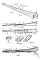
- an apparatus for the high speed production of a jacket component for a smoking article, which jacket component comprises, FIGS. 5A,5B, a removable tubular support member "A", a layer or layers “B” of compressible resilient material, preferably a fibrous material, having a preferred thickness of about 0.5 to about 2.5 mm, more preferably about 1 to 2 mm, circumferentially disposed about the support member (FIG. 5A) and an outer wrapper "C" circumferentially disposed about the layer of material to provide a predetermined final size (FIG. 5B).
- the wrapped component is preferably formed continuously from a web of fibrous material and a support member supplied from a large reel. After forming, the continuous length of the wrapped component is cut into pieces of predetermined size, usually a multiple of the size desired for the ultimate jacket component piece that is to be used for one smoking article.
- FIG. 5B An apparatus for forming the wrapped component 35 (FIG. 5B) is diagrammatically illustrated in FIG. 11.
- Support “A” is fed with layer or layers “B” of compressible resilient material into forming device 10 to form composite member 30.
- Composite member 30 is fed into a conventional wrapping device 60 where wrapper "C” is circumscribed around the composite member 30.
- the wrapped jacket component 35 is cut by a conventional cutting device 65 into desired lengths for further use in making smoking articles.
- FIGS. 1 to 3 illustrate a preferred forming device 10 for continuously forming the non-wrapped component or composite member 30 (FIG. 5A).
- Forming device 10 has a first open, funnel or trumpet-like inlet end 11 that is wide enough to receive the full width of the web of fibrous material "B" (see FIG. 7A) being used.
- the curved or arcuate inner surface of device 10 tapers inwardly from the entrance end 11 to the exit end 15 through which the composite member 30 (without an outer wrapper) leaves the device.
- the forming device defines a passageway having a generally decreasing cross-sectional area from the entrance end to the exit end.
- device 10 comprises three sections 17, 18, 19 formed in one integral piece. However, each of the sections could be formed separately and mechanically held together during use.
- the first section 17 is the entrance section. This section has an inner curved surface 27 that tapers inwardly away from opening 12 in the entrance end 11.
- the inner curved surface 27 of the entrance section 17 provides an opening 12 of sufficient width to permit the web "B" to enter without distortion (FIG. 7A).
- the second section 18 (see FIGS. 2, 7C) is the mid section of the device.
- This section 18 has an inner curved surface 28 that continues to taper inwardly away from the first section 17.
- the mid section 18 also has a arcuate or curved separate forming surface 24 (FIGS. 2, 3, 4, 7C) attached at one side to surface 28 and extending partially across the open area enclosed by surface 28 (FIGS. 4, 7C).
- the forming surface 24 folds one longitudinal edge 37 of web "B" over and in contact with support "A" while permitting the other longitudinal edge 38 of web “B” to pass by surface 24 constrained only by the curvature and taper of surface 28 (FIG. 7C).
- the forming surface may be provided by an insert 70 (FIGS. 12 - 17) having forming surface 24.
- Insert 70 is set into the mid section of the tapered funnel like device 10 as illustrated in FIG. 12.
- curved surface 75 has a radius of about 0.156 in. to fold layer "B" in contact with support "A".
- the third section 19 has a curved surface 29 that continues the inward taper from the mid section 18 to the exit end 15 where the composite member 30 (FIG. 5A) is formed to a predetermined size, preferably with web "B" compressed about tube "A".
- the other longitudinal edge 38 of the web “B” is folded over and in contact with removable support member "A” so that longitudinal edges 37, 38 are brought together to make a resulting layer having substantial uniformity. It is believed that the two edges 37, 38 are brought together in an interengaged or interlaced manner (FIG. 5A) rather than squarely abutting, edge to edge.
- web "B” is substantially uniformly wrapped around tube "A", i.e.
- the forming device 10 can be used on, for example, a Hauni KDF-2 filter making machine.
- the composite member 30, FIG. 5A is wrapped with conventional cigarette paper wrapping "C", FIG. 5B, in a conventional wrapping device on the KDF-2 immediately upon exiting the forming device 10.
- the forming device 10 is placed over a channel-shaped member 41 (FIGS. 6, 8), embodying a semi-circular surface 45 (FIG. 8) as in the Hauni KDF-2.
- the surface 45 cooperates with the forming device 10 to maintain the shape of the composite member 30.
- the outer wrapper "C", FIG. 8, usually conventional cigarette paper, is fed between the forming device 10 and the channel-shaped guide 41 (see FIGS. 6, 8).
- the diameter of the component is fixed.
- a cutter (see 65, FIG. 11) is arranged transversely of the wrapping device for cutting the wrapped composite member 30 into predetermined lengths for further handling in making smoking articles.
- the lengths are a multiple of the size desired to be used for each smoking article. For example, if a 10 mm component length is used for each smoking article, the length of the wrapped composite member may be, for example, 80 mm.
- a tube made of low density polyethylene having an outer diameter of 0.178 inches with a 0.020 inch wall thickness may be used as the removable support member.
- a glass fiber web about 0.032 inch thick having a density of about 160 to 180 g/m2 may be used to wrap the tube.
- a material thickness of about 1.5 to 1.6 mm around the tube two layers of the glass fiber material are used and wrapped simultaneously around the tubular support member "B" by the forming device 10.
- a web width of the material of about 19 mm is sufficient to wrap around the tubular support member to obtain the final composite member 30 having a circumference of about 24.1 mm.
- One layer of fibrous web can be used if provided in a suitable thickness and width.
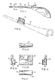
- FIGS. 9 and 10 An alternative forming device 50 made in accordance with the present invention is shown in FIGS. 9 and 10.
- the forming device 50 comprises a frusto conical shaped funnel 51 made, for example, from about 18 gauge stainless steel sheet.
- the large open inlet first end 51a through which the web and support member enter is about one inch inside diameter (I.D.).
- the funnel 51 from tapers down to about 11/32 inch I.D. at the exit end 51b and one edge 53 of the stainless sheet is spaced away from the other edge 54 leaving a gap of about 3/32 inch at the exit end.
- a bracket 52 is used to position the funnel 57 on a modified filter making apparatus.
- Forming device 50 comprises curved surfaces that perform the function of the first two sections (17, 18) of device 10 which was discussed above.
- a second tapered conical section 55 (FIG. 9) which is used in conjunction with forming device 50, performs the function of the third section (19) of device 10.
- FIG. 10 as tubular support A exits from the funnel 51, one longitudinal edge 37 of web "B” is folded over tube “A” under edge 54 of the device 50 while the second longitudinal edge 38 of web 35 extends along the inner surface of the funnel 51 toward edge 53.
- the support tube A and web “B” After exiting from the forming device 50, the support tube A and web “B” enter immediately into a tapered section 55 where the second longitudinal edge 38 of web “B” is folded proximate the first and web “B” is compressed, at least slightly, around tube “A” to a predetermined size as the composite member 30 exits the tapered part 55.
- the composite member can then be wrapped with an outer wrapper with a conventional wrapping device (FIG. 11), as discussed above.
- cross-sectional shaped support members can be wrapped with a fibrous web, in accord with the invention, by suitable modification of the cross-section of the forming device used.
- a preferred method for making jacket components in accord with the present invention comprises providing a substantially continuous length of fibrous material, for instance, in the form of a web or ribbon of predetermined width and thickness wound on a reel or spool and providing a substantially continuous support member such as tubing wound on a reel or spool.
- the web and support member are brought together longitudinally and the web is longitudinally folded around the support member to have one edge contiguous to the other edge.
- the fibrous layer is then compressed to provide a predetermined final size wherein the support member is substantially uniformly wrapped with the fibrous material.
- the sized member is then wrapped with an outer wrapper to maintain the final size.
- the wrapped composite member is preferably cut into lengths that are a multiple of the length of a jacket component used for making a smoking article.
Landscapes
- Cigarettes, Filters, And Manufacturing Of Filters (AREA)
- Manufacture Of Tobacco Products (AREA)
Applications Claiming Priority (2)
| Application Number | Priority Date | Filing Date | Title |
|---|---|---|---|
| US07/097,240 US4893637A (en) | 1987-09-15 | 1987-09-15 | Apparatus and methods for making components of a smoking article |
| US97240 | 2002-03-12 |
Publications (3)
| Publication Number | Publication Date |
|---|---|
| EP0307686A2 true EP0307686A2 (de) | 1989-03-22 |
| EP0307686A3 EP0307686A3 (en) | 1990-08-16 |
| EP0307686B1 EP0307686B1 (de) | 1994-11-23 |
Family
ID=22262392
Family Applications (1)
| Application Number | Title | Priority Date | Filing Date |
|---|---|---|---|
| EP88113937A Expired - Lifetime EP0307686B1 (de) | 1987-09-15 | 1988-08-26 | Einrichtung zur Herstellung der Bestandteile eines Rauchartikels |
Country Status (9)
| Country | Link |
|---|---|
| US (1) | US4893637A (de) |
| EP (1) | EP0307686B1 (de) |
| JP (1) | JPH01120272A (de) |
| KR (1) | KR960009180B1 (de) |
| AT (1) | ATE114219T1 (de) |
| CA (1) | CA1299049C (de) |
| DE (1) | DE3852160T2 (de) |
| ES (1) | ES2063748T3 (de) |
| GR (1) | GR3015008T3 (de) |
Cited By (5)
| Publication number | Priority date | Publication date | Assignee | Title |
|---|---|---|---|---|
| WO2008033053A1 (en) * | 2006-09-12 | 2008-03-20 | Obschestvo S Ogranichennoy Otvetstvennostyu 'darsail-Asp' | Cigarette rod former |
| US20150080198A1 (en) * | 2009-03-26 | 2015-03-19 | British American Tobacco (Investments) Limited | Rod for a Smoking Article and Method and Apparatus for Manufacture |
| WO2015011619A3 (en) * | 2013-07-22 | 2015-06-25 | International Tobacco Machinery Poland Sp. Z O.O. | Method and member for guiding a strand of filter fibers and filter rod making machine |
| WO2019158313A1 (en) * | 2018-02-15 | 2019-08-22 | Philip Morris Products S.A. | Method and apparatus for folding a web of material |
| WO2025104065A1 (en) * | 2023-11-17 | 2025-05-22 | Philip Morris Products S.A. | Web conveying guide |
Families Citing this family (40)
| Publication number | Priority date | Publication date | Assignee | Title |
|---|---|---|---|---|
| IT1183599B (it) * | 1985-05-10 | 1987-10-22 | Inphardial Spa | Dispositivo per determinare la quantita'di acqua plasmatica rimossa durante una seduta di dialisi extra - corporea |
| US5415186A (en) * | 1990-08-15 | 1995-05-16 | R. J. Reynolds Tobacco Company | Substrates material for smoking articles |
| US5396911A (en) * | 1990-08-15 | 1995-03-14 | R. J. Reynolds Tobacco Company | Substrate material for smoking articles |
| US5105837A (en) * | 1990-08-28 | 1992-04-21 | R. J. Reynolds Tobacco Company | Smoking article with improved wrapper |
| US5163452A (en) * | 1990-09-20 | 1992-11-17 | R. J. Reynolds Tobacco Company | Rod making apparatus for use in the manufacture of smoking articles |
| US5348027A (en) * | 1991-02-14 | 1994-09-20 | R. J. Reynolds Tobacco Company | Cigarette with improved substrate |
| US5203355A (en) * | 1991-02-14 | 1993-04-20 | R. J. Reynolds Tobacco Company | Cigarette with cellulosic substrate |
| US5178167A (en) * | 1991-06-28 | 1993-01-12 | R. J. Reynolds Tobacco Company | Carbonaceous composition for fuel elements of smoking articles and method of modifying the burning characteristics thereof |
| TR25593A (tr) * | 1992-01-14 | 1993-07-01 | Inter Muehendislik Danismanlik | INFRARED ELEKTROOPTIK KOMüNIKASYON CIHAZI |
| CA2466075C (en) * | 1992-03-25 | 2007-05-01 | Japan Tobacco, Inc. | Components for smoking articles and process for making same |
| US5345955A (en) * | 1992-09-17 | 1994-09-13 | R. J. Reynolds Tobacco Company | Composite fuel element for smoking articles |
| US5469871A (en) * | 1992-09-17 | 1995-11-28 | R. J. Reynolds Tobacco Company | Cigarette and method of making same |
| PH30299A (en) * | 1993-04-07 | 1997-02-20 | Reynolds Tobacco Co R | Fuel element composition |
| US5588446A (en) * | 1993-06-02 | 1996-12-31 | R. J. Reynolds Tobacco Company | Cigarette with improved cellulosic substrate |
| US5546965A (en) * | 1994-06-22 | 1996-08-20 | R. J. Reynolds Tobacco Company | Cigarette with improved fuel element insulator |
| US5533530A (en) | 1994-09-01 | 1996-07-09 | R. J. Reynolds Tobacco Company | Tobacco reconstitution process |
| US5902431A (en) * | 1997-06-04 | 1999-05-11 | R. J. Reynolds Tobacco Company | Composite web forming apparatus and method |
| US10188140B2 (en) | 2005-08-01 | 2019-01-29 | R.J. Reynolds Tobacco Company | Smoking article |
| US20070215167A1 (en) * | 2006-03-16 | 2007-09-20 | Evon Llewellyn Crooks | Smoking article |
| US9220301B2 (en) | 2006-03-16 | 2015-12-29 | R.J. Reynolds Tobacco Company | Smoking article |
| US8464726B2 (en) | 2009-08-24 | 2013-06-18 | R.J. Reynolds Tobacco Company | Segmented smoking article with insulation mat |
| US8424538B2 (en) | 2010-05-06 | 2013-04-23 | R.J. Reynolds Tobacco Company | Segmented smoking article with shaped insulator |
| US8839799B2 (en) | 2010-05-06 | 2014-09-23 | R.J. Reynolds Tobacco Company | Segmented smoking article with stitch-bonded substrate |
| US9149072B2 (en) | 2010-05-06 | 2015-10-06 | R.J. Reynolds Tobacco Company | Segmented smoking article with substrate cavity |
| EP2647300B1 (de) | 2010-05-06 | 2019-04-24 | R.J. Reynolds Tobacco Company | Segmentierter Rauchartikel |
| US9301546B2 (en) | 2010-08-19 | 2016-04-05 | R.J. Reynolds Tobacco Company | Segmented smoking article with shaped insulator |
| DE102010043350A1 (de) * | 2010-11-03 | 2012-05-03 | Hauni Maschinenbau Ag | Vorrichtung zur Herstellung von Koaxialfiltern für stabförmige Rauchartikel |
| DE102010043348A1 (de) * | 2010-11-03 | 2012-05-03 | Hauni Maschinenbau Ag | Vorrichtung zur Herstellung von Koaxilafiltern für stabförmige Rauchartikel |
| IN2014CN02160A (de) | 2011-09-20 | 2015-05-29 | Reynolds Tobacco Co R | |
| US9788571B2 (en) | 2013-09-25 | 2017-10-17 | R.J. Reynolds Tobacco Company | Heat generation apparatus for an aerosol-generation system of a smoking article, and associated smoking article |
| US10154689B2 (en) | 2015-06-30 | 2018-12-18 | R.J. Reynolds Tobacco Company | Heat generation segment for an aerosol-generation system of a smoking article |
| US20170055576A1 (en) | 2015-08-31 | 2017-03-02 | R. J. Reynolds Tobacco Company | Smoking article |
| US11744296B2 (en) | 2015-12-10 | 2023-09-05 | R. J. Reynolds Tobacco Company | Smoking article |
| US10314334B2 (en) | 2015-12-10 | 2019-06-11 | R.J. Reynolds Tobacco Company | Smoking article |
| US11717018B2 (en) | 2016-02-24 | 2023-08-08 | R.J. Reynolds Tobacco Company | Smoking article comprising aerogel |
| DE102017108789A1 (de) * | 2017-04-25 | 2018-10-25 | Hauni Maschinenbau Gmbh | Verfahren und Strangmaschine zum Herstellen von doppellagigen Röhrchen der Tabak verarbeitenden Industrie |
| US20190254335A1 (en) | 2018-02-22 | 2019-08-22 | R.J. Reynolds Tobacco Company | System for debossing a heat generation member, a smoking article including the debossed heat generation member, and a related method |
| US12478112B2 (en) | 2018-10-30 | 2025-11-25 | R.J. Reynolds Tobacco Company | Smoking article cartridge |
| CN111616407B (zh) * | 2020-04-16 | 2021-06-15 | 红云红河烟草(集团)有限责任公司 | 一种方形烟支成型机 |
| CN114983018A (zh) * | 2022-05-24 | 2022-09-02 | 云南中烟工业有限责任公司 | 一种三角形间隔的全中空滤棒及其成型方法 |
Family Cites Families (14)
| Publication number | Priority date | Publication date | Assignee | Title |
|---|---|---|---|---|
| US2164702A (en) * | 1936-02-29 | 1939-07-04 | Davidson Glenn | Method and apparatus for making cigarette mouthpieces |
| US3016945A (en) * | 1960-04-25 | 1962-01-16 | Eastman Kodak Co | Method and apparatus for forming tobacco smoke filters |
| FR1264962A (fr) * | 1960-08-11 | 1961-06-23 | Perfectionnements apportés aux cigarettes et aux procédés et machines pour leur fabrication | |
| US3396061A (en) * | 1964-06-01 | 1968-08-06 | Celanese Corp | Smoke filters |
| GB1214491A (en) * | 1967-02-21 | 1970-12-02 | Molins Machine Co Ltd | Improvements in the manufacture of composite of flexible material |
| US3774508A (en) * | 1968-05-08 | 1973-11-27 | American Filtrona Corp | Apparatus for making filter means |
| FR2033749A5 (de) * | 1970-01-23 | 1970-12-04 | Yatrides Georges | |
| US3860011A (en) * | 1973-08-27 | 1975-01-14 | Liggett & Myers Inc | Hollow filter |
| US4357950A (en) * | 1980-05-27 | 1982-11-09 | American Filtrona Corporation | Tobacco smoke filter having improved tar/carbon monoxide ratio |
| US4508525A (en) * | 1980-05-27 | 1985-04-02 | American Filtrona Corporation | Method and apparatus for producing tobacco smoke filter having improved tar/carbon monoxide ratio |
| JPS5836084B2 (ja) * | 1981-07-04 | 1983-08-06 | 蚕糸試験場長 | 繰糸機多数緒に於ける生糸生産情報計測装置 |
| US4549875A (en) * | 1983-06-02 | 1985-10-29 | R. J. Reynolds Tobacco Co. | Manufacture of tobacco smoke filters |
| US4585015A (en) * | 1984-11-16 | 1986-04-29 | Brown & Williamson Tobacco Corporation | Cigarette filter |
| GB8502651D0 (en) * | 1985-02-01 | 1985-03-06 | British American Tobacco Co | Smoking articles |
-
1987
- 1987-09-15 US US07/097,240 patent/US4893637A/en not_active Expired - Fee Related
-
1988
- 1988-08-26 DE DE3852160T patent/DE3852160T2/de not_active Expired - Lifetime
- 1988-08-26 ES ES88113937T patent/ES2063748T3/es not_active Expired - Lifetime
- 1988-08-26 AT AT88113937T patent/ATE114219T1/de not_active IP Right Cessation
- 1988-08-26 EP EP88113937A patent/EP0307686B1/de not_active Expired - Lifetime
- 1988-09-13 JP JP63227643A patent/JPH01120272A/ja active Pending
- 1988-09-14 CA CA000577346A patent/CA1299049C/en not_active Expired - Lifetime
- 1988-09-15 KR KR1019880011907A patent/KR960009180B1/ko not_active Expired - Lifetime
-
1995
- 1995-02-08 GR GR950400250T patent/GR3015008T3/el unknown
Cited By (8)
| Publication number | Priority date | Publication date | Assignee | Title |
|---|---|---|---|---|
| WO2008033053A1 (en) * | 2006-09-12 | 2008-03-20 | Obschestvo S Ogranichennoy Otvetstvennostyu 'darsail-Asp' | Cigarette rod former |
| RU2345685C2 (ru) * | 2006-09-12 | 2009-02-10 | Общество С Ограниченной Ответственностью "Дарсайл-Асп" | Формирователь сигаретного штранга |
| US20150080198A1 (en) * | 2009-03-26 | 2015-03-19 | British American Tobacco (Investments) Limited | Rod for a Smoking Article and Method and Apparatus for Manufacture |
| US10285435B2 (en) * | 2009-03-26 | 2019-05-14 | British American Tobacco (Investments) Limited | Rod for a smoking article and method and apparatus for manufacture |
| WO2015011619A3 (en) * | 2013-07-22 | 2015-06-25 | International Tobacco Machinery Poland Sp. Z O.O. | Method and member for guiding a strand of filter fibers and filter rod making machine |
| WO2019158313A1 (en) * | 2018-02-15 | 2019-08-22 | Philip Morris Products S.A. | Method and apparatus for folding a web of material |
| US12089629B2 (en) | 2018-02-15 | 2024-09-17 | Philip Morris Products S.A. | Method and apparatus for folding a web of material |
| WO2025104065A1 (en) * | 2023-11-17 | 2025-05-22 | Philip Morris Products S.A. | Web conveying guide |
Also Published As
| Publication number | Publication date |
|---|---|
| ATE114219T1 (de) | 1994-12-15 |
| KR960009180B1 (ko) | 1996-07-16 |
| KR890004646A (ko) | 1989-05-09 |
| DE3852160T2 (de) | 1995-06-01 |
| DE3852160D1 (de) | 1995-01-05 |
| EP0307686B1 (de) | 1994-11-23 |
| ES2063748T3 (es) | 1995-01-16 |
| EP0307686A3 (en) | 1990-08-16 |
| JPH01120272A (ja) | 1989-05-12 |
| US4893637A (en) | 1990-01-16 |
| CA1299049C (en) | 1992-04-21 |
| GR3015008T3 (en) | 1995-05-31 |
Similar Documents
| Publication | Publication Date | Title |
|---|---|---|
| US4893637A (en) | Apparatus and methods for making components of a smoking article | |
| JP2767445B2 (ja) | 喫煙物品製造のためのロッド製造装置 | |
| US4459998A (en) | Manufacture of cigarettes | |
| EP0246107A2 (de) | Zigarettenstränge und Filter mit Fasern, hergestellt aus blattförmigen Materialien | |
| NZ207667A (en) | Cigarette making system includes a loose plunger rod | |
| KR20210102205A (ko) | 담배 산업의 관형 세그먼트를 제조하기 위한 기계 | |
| US5203757A (en) | Method and apparatus for producing tobacco smoke filter rods | |
| JP2023134819A (ja) | エアロゾル発生材からなるストランドを搬送するためのコンベアおよび方法、エアロゾル発生材からなるロッドの製造装置および方法 | |
| JP3002173B2 (ja) | たばこフィルターの製造方法およびその装置 | |
| JPS6248369A (ja) | 巻きタバコ用フイルター・ユニツトとその製法 | |
| GB2069310A (en) | Manufacture of cigarettes | |
| DE2556332A1 (de) | Verfahren und maschine zum herstellen eines mehrwandigen papierrohres fuer rauchartikel-mundstueckhuelsen | |
| US11800889B2 (en) | Tongue with pre-folding section | |
| EP0790782A1 (de) | Verfahren und einrichtung zum einwickeln eines stranges aus rauchmaterial | |
| GB2058542A (en) | Method and apparatus for the manufacture of cigarette filters containing particulate material | |
| EP0209319B1 (de) | Tabakprodukt mit einer Filterspitze und einem spiralförmig angebrachten Deckblatt und Verfahren zur Herstellung dieses Produktes | |
| EP4417068B1 (de) | Faltvorrichtung zum falten eines in einem kontinuierlichen strang der tabakindustrie platzierten strangs aus füllmaterial | |
| CN221980049U (zh) | 用于气雾产生制品或吸烟制品的元件以及多段式产品 | |
| JPH11318417A (ja) | シース・コア型たばこフィルターの製造方法およびその装置 | |
| EP0483931B1 (de) | Zigarrenähnliches Tabakprodukt und Verfahren zur Herstellung eines solchen Produktes | |
| JPS586467B2 (ja) | シガレットフィルタ−の製造法 | |
| GB2160407A (en) | Improvements relating to smoking article mouthpieces | |
| CA2110751A1 (en) | Cigarette filter tip for a hand rolled cigarette | |
| JPH06327458A (ja) | 変流突起付ガイドパイプを有するタバコフィルタ製造装置 | |
| EP0361903A1 (de) | Vorrichtung zur Kontrolle von Filtersträngen für Zigaretten |
Legal Events
| Date | Code | Title | Description |
|---|---|---|---|
| PUAI | Public reference made under article 153(3) epc to a published international application that has entered the european phase |
Free format text: ORIGINAL CODE: 0009012 |
|
| AK | Designated contracting states |
Kind code of ref document: A2 Designated state(s): AT BE CH DE ES FR GB GR IT LI LU NL SE |
|
| PUAL | Search report despatched |
Free format text: ORIGINAL CODE: 0009013 |
|
| AK | Designated contracting states |
Kind code of ref document: A3 Designated state(s): AT BE CH DE ES FR GB GR IT LI LU NL SE |
|
| 17P | Request for examination filed |
Effective date: 19910201 |
|
| 17Q | First examination report despatched |
Effective date: 19920205 |
|
| GRAA | (expected) grant |
Free format text: ORIGINAL CODE: 0009210 |
|
| AK | Designated contracting states |
Kind code of ref document: B1 Designated state(s): AT BE CH DE ES FR GB GR IT LI LU NL SE |
|
| REF | Corresponds to: |
Ref document number: 114219 Country of ref document: AT Date of ref document: 19941215 Kind code of ref document: T |
|
| REF | Corresponds to: |
Ref document number: 3852160 Country of ref document: DE Date of ref document: 19950105 |
|
| REG | Reference to a national code |
Ref country code: ES Ref legal event code: FG2A Ref document number: 2063748 Country of ref document: ES Kind code of ref document: T3 |
|
| ITF | It: translation for a ep patent filed | ||
| EAL | Se: european patent in force in sweden |
Ref document number: 88113937.2 |
|
| ET | Fr: translation filed | ||
| REG | Reference to a national code |
Ref country code: GR Ref legal event code: FG4A Free format text: 3015008 |
|
| PLBE | No opposition filed within time limit |
Free format text: ORIGINAL CODE: 0009261 |
|
| STAA | Information on the status of an ep patent application or granted ep patent |
Free format text: STATUS: NO OPPOSITION FILED WITHIN TIME LIMIT |
|
| 26N | No opposition filed | ||
| REG | Reference to a national code |
Ref country code: GB Ref legal event code: 727 |
|
| REG | Reference to a national code |
Ref country code: GB Ref legal event code: 727A |
|
| REG | Reference to a national code |
Ref country code: GB Ref legal event code: 727B |
|
| REG | Reference to a national code |
Ref country code: GB Ref legal event code: SP |
|
| REG | Reference to a national code |
Ref country code: CH Ref legal event code: PUE Owner name: R. J. REYNOLDS TOBACCO COMPANY TRANSFER- JAPAN TOB |
|
| NLS | Nl: assignments of ep-patents |
Owner name: JAPAN TOBACCO INC. |
|
| REG | Reference to a national code |
Ref country code: GB Ref legal event code: 732E |
|
| REG | Reference to a national code |
Ref country code: FR Ref legal event code: TP |
|
| REG | Reference to a national code |
Ref country code: GB Ref legal event code: IF02 |
|
| PGFP | Annual fee paid to national office [announced via postgrant information from national office to epo] |
Ref country code: ES Payment date: 20070813 Year of fee payment: 20 |
|
| PGFP | Annual fee paid to national office [announced via postgrant information from national office to epo] |
Ref country code: LU Payment date: 20070820 Year of fee payment: 20 |
|
| PGFP | Annual fee paid to national office [announced via postgrant information from national office to epo] |
Ref country code: DE Payment date: 20070921 Year of fee payment: 20 |
|
| REG | Reference to a national code |
Ref country code: CH Ref legal event code: PCAR Free format text: ISLER & PEDRAZZINI AG;POSTFACH 1772;8027 ZUERICH (CH) |
|
| PGFP | Annual fee paid to national office [announced via postgrant information from national office to epo] |
Ref country code: CH Payment date: 20070821 Year of fee payment: 20 Ref country code: AT Payment date: 20070827 Year of fee payment: 20 |
|
| PGFP | Annual fee paid to national office [announced via postgrant information from national office to epo] |
Ref country code: GB Payment date: 20070820 Year of fee payment: 20 |
|
| PGFP | Annual fee paid to national office [announced via postgrant information from national office to epo] |
Ref country code: IT Payment date: 20070821 Year of fee payment: 20 Ref country code: NL Payment date: 20070831 Year of fee payment: 20 Ref country code: BE Payment date: 20070806 Year of fee payment: 20 Ref country code: SE Payment date: 20070817 Year of fee payment: 20 |
|
| PGFP | Annual fee paid to national office [announced via postgrant information from national office to epo] |
Ref country code: FR Payment date: 20070706 Year of fee payment: 20 |
|
| PGFP | Annual fee paid to national office [announced via postgrant information from national office to epo] |
Ref country code: GR Payment date: 20070705 Year of fee payment: 20 |
|
| BE20 | Be: patent expired |
Owner name: *JAPAN TOBACCO INC. UNE SOCIETE ORGANISEE ET EXIST Effective date: 20080826 |
|
| REG | Reference to a national code |
Ref country code: CH Ref legal event code: PL |
|
| REG | Reference to a national code |
Ref country code: GB Ref legal event code: PE20 Expiry date: 20080825 |
|
| EUG | Se: european patent has lapsed | ||
| PG25 | Lapsed in a contracting state [announced via postgrant information from national office to epo] |
Ref country code: NL Free format text: LAPSE BECAUSE OF EXPIRATION OF PROTECTION Effective date: 20080826 |
|
| NLV7 | Nl: ceased due to reaching the maximum lifetime of a patent |
Effective date: 20080826 |
|
| REG | Reference to a national code |
Ref country code: ES Ref legal event code: FD2A Effective date: 20080827 |
|
| PG25 | Lapsed in a contracting state [announced via postgrant information from national office to epo] |
Ref country code: GB Free format text: LAPSE BECAUSE OF EXPIRATION OF PROTECTION Effective date: 20080825 |
|
| PG25 | Lapsed in a contracting state [announced via postgrant information from national office to epo] |
Ref country code: ES Free format text: LAPSE BECAUSE OF EXPIRATION OF PROTECTION Effective date: 20080827 |