EP0307522A1 - Appareil pour conduire des gaz chauds d'un tuyau d'échappement - Google Patents
Appareil pour conduire des gaz chauds d'un tuyau d'échappement Download PDFInfo
- Publication number
- EP0307522A1 EP0307522A1 EP87308158A EP87308158A EP0307522A1 EP 0307522 A1 EP0307522 A1 EP 0307522A1 EP 87308158 A EP87308158 A EP 87308158A EP 87308158 A EP87308158 A EP 87308158A EP 0307522 A1 EP0307522 A1 EP 0307522A1
- Authority
- EP
- European Patent Office
- Prior art keywords
- conduit
- fitting
- outlet
- exhaust pipe
- inlet
- Prior art date
- Legal status (The legal status is an assumption and is not a legal conclusion. Google has not performed a legal analysis and makes no representation as to the accuracy of the status listed.)
- Withdrawn
Links
Images


Classifications
-
- F—MECHANICAL ENGINEERING; LIGHTING; HEATING; WEAPONS; BLASTING
- F16—ENGINEERING ELEMENTS AND UNITS; GENERAL MEASURES FOR PRODUCING AND MAINTAINING EFFECTIVE FUNCTIONING OF MACHINES OR INSTALLATIONS; THERMAL INSULATION IN GENERAL
- F16L—PIPES; JOINTS OR FITTINGS FOR PIPES; SUPPORTS FOR PIPES, CABLES OR PROTECTIVE TUBING; MEANS FOR THERMAL INSULATION IN GENERAL
- F16L3/00—Supports for pipes, cables or protective tubing, e.g. hangers, holders, clamps, cleats, clips, brackets
-
- E—FIXED CONSTRUCTIONS
- E03—WATER SUPPLY; SEWERAGE
- E03B—INSTALLATIONS OR METHODS FOR OBTAINING, COLLECTING, OR DISTRIBUTING WATER
- E03B7/00—Water main or service pipe systems
- E03B7/09—Component parts or accessories
- E03B7/10—Devices preventing bursting of pipes by freezing
- E03B7/12—Devices preventing bursting of pipes by freezing by preventing freezing
-
- F—MECHANICAL ENGINEERING; LIGHTING; HEATING; WEAPONS; BLASTING
- F16—ENGINEERING ELEMENTS AND UNITS; GENERAL MEASURES FOR PRODUCING AND MAINTAINING EFFECTIVE FUNCTIONING OF MACHINES OR INSTALLATIONS; THERMAL INSULATION IN GENERAL
- F16L—PIPES; JOINTS OR FITTINGS FOR PIPES; SUPPORTS FOR PIPES, CABLES OR PROTECTIVE TUBING; MEANS FOR THERMAL INSULATION IN GENERAL
- F16L25/00—Constructive types of pipe joints not provided for in groups F16L13/00 - F16L23/00 ; Details of pipe joints not otherwise provided for, e.g. electrically conducting or insulating means
- F16L25/14—Joints for pipes of different diameters or cross-section
Definitions
- This invention relates to an elongated conduit for conducting exhaust gases from an exhaust pipe to an object to be heated.
- Exhaust gases from automobiles and other internal combustion engine devices have been employed in the past for various heating operations.
- permanent installations on automobiles have been used to heat carburettors or the interior of the automobile by means of a heat exchanger.
- One such device is disclosed, for example, in Canadian Patent No. 144,864 to Matthews.
- Canadian Patent No. 285,104 to Huntley discloses a heater employing exhaust gases to heat the differential housing of an automobile.
- Canadian Patent No. 337,940 to Miller discloses another device using exhaust gases to heat a transmission and differential housing.
- Canadian Patent No. 1,099,680 to Prucyk discloses a device employing exhaust gases to heat paint for a pavement striper.
- the devices discussed above do not offer a portable apparatus suitable for temporary connection to various exhaust pipes and which can be easily manoeuvred and positioned to heat components of an automobile or exterior objects requiring heating.
- the conduit has a portion comprising a spirally wound conduit which is flexible when twisted in one direction and locks in a desired position when twisted in a direction opposite the one direction.
- the inlet fitting may have a seal for fitting exhaust pipes of different sizes
- the seal comprises a resilient annular member having a central aperture for receiving the exhaust pipe.
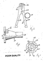
- FIG. 1 shows an apparatus 1 for conducting hot gases from an exhaust pipe 2 to an object to be heated, in this case an outdoor water faucet 4.
- the apparatus may be connected to the exhaust pipe of other equipment employing an internal combustion engine.
- the apparatus has three major components.
- the first is an elongated, flexible conduit 6 which has an inlet end 8 and an outlet end 10.
- the conduit has two portions.
- the first portion 12 is, in this preferred embodiment, a flexible cotton hose, similar to those used for fire hoses. Of course other flexible conduits capable of carrying hot exhaust gases could be substituted.
- the conduit 6 has a second portion portion 14 connected to first portion 12 at a point 16.
- the second portion 14 is made of a spirally wound conduit. This is shown in more detail in Figure 10.
- conduits are commercially available and are typically used as electrical conduits. A large diameter such conduit is required for this apparatus.
- Such conduits are made of a single length of sheet metal 18 which is shaped and interlocked in manufacture to form a spiral, flexible joint 20 extending along the length of the conduit. Because of the spiral winding, the conduit can be tightened by twisting it in one direction, for example clockwise, according to the direction of the spiral. By "untwisting" the conduit in the opposite direction, for example counter-clockwise, the conduit is loosened and becomes more flexible.
- the apparatus also includes an inlet fitting 22 which is shown in better detail in Figure 6 and 7.
- the inlet fitting is in the shape of a truncated cone with a larger end 24 which is the open end directed towards the exhaust pipe 2 as shown in Figure 1.
- the opposite end 26 is connected to portion 12 of the conduit 6.
- the inlet fitting has a seal which comprises a resilient annular member 28, shown best in figure 7, which extends outwardly from a central aperture 30 and is held between a pair of outer, rigid rings 32 and 34. This is shown best in the breakaway in Figure 6.
- the member is made of heat resistant rubber in the preferred embodiment, although alternative materials could be substituted.
- the annular member 38 has a plurality of sections 36 which are each separated by a radially extending slit 40, each of which extends from aperture 30 to rings 32 and 34.
- the aperture 30 is slightly smaller than any exhaust pipe the apparatus is adapted to fit.
- the slits and the resilient material of member 28 allow inlet fitting 22 to be forced over exhaust pipes somewhat larger than aperture 30.
- the inlet fitting is designed to fit a wide range of exhaust pipe sizes.
- outlet fitting 42 shown in Figfure 1 and in better detail in Figure 2.
- This outlet fitting may be seen to be in the shape of a truncated cone which tapers outwardly from end 43 which is connected to portion 14 of conduit 6 towards open end 46 where exhaust gases are discharged. Since end 46 has a diameter smaller than end 43 this fitting acts as a nozzle to concentrate the exhaust gases at a higher velocity on a limited area. This increases the heating effect for a relatively small area.
- FIG. 3 An alternative outlet fitting 48 is shown in Figure 3 and 4.
- This fitting has an end 50 which is connected to portion 14 of conduit 6 and an open end 52 which is an elongated slot as best shown in Figure 4. It may be seen that the fitting is flattened and fan-shaped to diffuse the exhaust gases over a relatively wide area. Thus this outlet fitting is used when the heating effect is desired over a more general area.
- a clamp 54 shown in detail in Figure 5, may be used to secure the outlet end of the apparatus in position so the exhaust gases are directed onto the object requiring heating.
- clamp 54 is used to secure portion 14 of conduit 6 to a vertical section of pipe 56 leading to faucet 4.
- the exhaust gases can be manually directed by the user holding outlet fitting 42 and directing the gases to the required spot.
- clamp 54 allows the apparatus to be clamped to some suitable point so the user can go about other activities.
- clamp 54 can be secured to some convenient part under the hood of the car, such as the radiator.
- the clamp is connected to portion 14 of conduit 6 near the end opposite fitting 42.
- clamp 54 is very similar to the type of clamp used on jumper cables for clamping to battery posts. It consists of a pair of members 58 and 60 which are pivotally connected by a pin 62. The members are resilient biased in the conventional manner so that jaws 64 and 66 are urged towards each other. The portion 14 of conduit 6 is twisted to lock portion 14 in position, as shown by way of example in Figure 1, and thus keep the exhaust gases trained on the object being heated with the aid of clamp 54.
- Figures 8 and 9 illustrate the type of connection used throughout.
- One of the members 68 which may be, for example, part of outlet fitting 42, is a straight section of pipe.
- the other member 70 is tapered and connected, for example, to portion 14 of conduit 6.
- the members are connected by holding member 68 firmly in one hand and inserting member 70 into member 68 with the other hand and then firmly pushing member 68 onto member 70 and turning them. This achieves the connection shown in Figure 9.
- the members are released by holding member 68 with one hand and with the other hand rocking member 70 back and forth once each way while pulling the members apart. Thus the members are disconnected as shown in Figure 8.
Landscapes
- Engineering & Computer Science (AREA)
- General Engineering & Computer Science (AREA)
- Mechanical Engineering (AREA)
- Health & Medical Sciences (AREA)
- Life Sciences & Earth Sciences (AREA)
- Hydrology & Water Resources (AREA)
- Public Health (AREA)
- Water Supply & Treatment (AREA)
- Exhaust Silencers (AREA)
Priority Applications (2)
| Application Number | Priority Date | Filing Date | Title |
|---|---|---|---|
| US06/851,349 US4693421A (en) | 1985-04-15 | 1986-04-14 | Apparatus for conducting hot gases from an exhaust pipe |
| EP87308158A EP0307522A1 (fr) | 1987-09-15 | 1987-09-15 | Appareil pour conduire des gaz chauds d'un tuyau d'échappement |
Applications Claiming Priority (1)
| Application Number | Priority Date | Filing Date | Title |
|---|---|---|---|
| EP87308158A EP0307522A1 (fr) | 1987-09-15 | 1987-09-15 | Appareil pour conduire des gaz chauds d'un tuyau d'échappement |
Publications (1)
| Publication Number | Publication Date |
|---|---|
| EP0307522A1 true EP0307522A1 (fr) | 1989-03-22 |
Family
ID=8198032
Family Applications (1)
| Application Number | Title | Priority Date | Filing Date |
|---|---|---|---|
| EP87308158A Withdrawn EP0307522A1 (fr) | 1985-04-15 | 1987-09-15 | Appareil pour conduire des gaz chauds d'un tuyau d'échappement |
Country Status (1)
| Country | Link |
|---|---|
| EP (1) | EP0307522A1 (fr) |
Cited By (3)
| Publication number | Priority date | Publication date | Assignee | Title |
|---|---|---|---|---|
| EP0780634A2 (fr) * | 1995-12-22 | 1997-06-25 | Betonwerke Heinrich Hess KG | Manchon d'accouplement |
| CN102667291A (zh) * | 2009-10-16 | 2012-09-12 | 蒲利美集团 | 用于废气排出系统的连接器系统 |
| US20220106961A1 (en) * | 2019-02-04 | 2022-04-07 | Edwards Japan Limited | Vacuum pump and connection port used in vacuum pump |
Citations (7)
| Publication number | Priority date | Publication date | Assignee | Title |
|---|---|---|---|---|
| US2558023A (en) * | 1948-06-22 | 1951-06-26 | William C Walsh | Exhaust attachment |
| US2789841A (en) * | 1951-11-13 | 1957-04-23 | Vance M Kramer | Flexible reducer boot |
| US3151613A (en) * | 1962-12-21 | 1964-10-06 | Howard Howard Herman | Snow and ice melting device |
| US3189021A (en) * | 1963-03-21 | 1965-06-15 | Paul T Giguere | Ice melter |
| DE1900876A1 (de) * | 1969-01-09 | 1970-08-20 | Karl Barst | Vorrichtung zum Auftauen verschneiter bzw.vereister Strassendecken durch die Abgase von Kraftfahrzeugmotoren |
| DE8402032U1 (de) * | 1984-01-25 | 1984-05-03 | Hans Huras Gmbh, 6437 Kirchheim | Kraftfahrzeug mit einer auspuffanlage |
| EP0151654A2 (fr) * | 1983-04-28 | 1985-08-21 | Horst Ludscheidt | Dispositif pour connecter une conduite de gaz à échappement, en particulier de véhicules à moteur |
-
1987
- 1987-09-15 EP EP87308158A patent/EP0307522A1/fr not_active Withdrawn
Patent Citations (7)
| Publication number | Priority date | Publication date | Assignee | Title |
|---|---|---|---|---|
| US2558023A (en) * | 1948-06-22 | 1951-06-26 | William C Walsh | Exhaust attachment |
| US2789841A (en) * | 1951-11-13 | 1957-04-23 | Vance M Kramer | Flexible reducer boot |
| US3151613A (en) * | 1962-12-21 | 1964-10-06 | Howard Howard Herman | Snow and ice melting device |
| US3189021A (en) * | 1963-03-21 | 1965-06-15 | Paul T Giguere | Ice melter |
| DE1900876A1 (de) * | 1969-01-09 | 1970-08-20 | Karl Barst | Vorrichtung zum Auftauen verschneiter bzw.vereister Strassendecken durch die Abgase von Kraftfahrzeugmotoren |
| EP0151654A2 (fr) * | 1983-04-28 | 1985-08-21 | Horst Ludscheidt | Dispositif pour connecter une conduite de gaz à échappement, en particulier de véhicules à moteur |
| DE8402032U1 (de) * | 1984-01-25 | 1984-05-03 | Hans Huras Gmbh, 6437 Kirchheim | Kraftfahrzeug mit einer auspuffanlage |
Cited By (5)
| Publication number | Priority date | Publication date | Assignee | Title |
|---|---|---|---|---|
| EP0780634A2 (fr) * | 1995-12-22 | 1997-06-25 | Betonwerke Heinrich Hess KG | Manchon d'accouplement |
| EP0780634A3 (fr) * | 1995-12-22 | 1999-01-20 | Betonwerke Heinrich Hess KG | Manchon d'accouplement |
| CN102667291A (zh) * | 2009-10-16 | 2012-09-12 | 蒲利美集团 | 用于废气排出系统的连接器系统 |
| CN102667291B (zh) * | 2009-10-16 | 2016-05-04 | 蒲利美集团 | 用于废气排出系统的连接器系统 |
| US20220106961A1 (en) * | 2019-02-04 | 2022-04-07 | Edwards Japan Limited | Vacuum pump and connection port used in vacuum pump |
Similar Documents
| Publication | Publication Date | Title |
|---|---|---|
| US4647072A (en) | Repair sleeve for piping | |
| US6231085B1 (en) | Tubing coupling and hose end combination, and related method | |
| US6837787B2 (en) | Flexible duct sleeve | |
| US4688833A (en) | Recreational vehicle discharge pipe adapter | |
| US4693421A (en) | Apparatus for conducting hot gases from an exhaust pipe | |
| US7104881B1 (en) | Locator ring insert with baffles | |
| JPS61502273A (ja) | パイプのたわみ継手 | |
| US4906032A (en) | Tail pipe coupling device | |
| US5511288A (en) | Adjustable loop clamp | |
| EP0307522A1 (fr) | Appareil pour conduire des gaz chauds d'un tuyau d'échappement | |
| US6702338B2 (en) | Flue gas conduit joining connection | |
| EP0255982A3 (en) | Non-return ball valve | |
| CA1256813A (fr) | Dispositif pour conduire des gaz chaud d'un tuyau d'echappement | |
| US3989282A (en) | Plug-type device for interconnecting conduits | |
| US2789841A (en) | Flexible reducer boot | |
| US11728635B2 (en) | Apparatus for joining extended lengths of conduit | |
| US7644956B2 (en) | Flexible duct sleeve | |
| US5741029A (en) | Piping adapter | |
| US4180286A (en) | Exhaust pipe safety clamp assembly and combination | |
| AU691922B2 (en) | A pipe coupling | |
| US3591142A (en) | Tools for split pipe collars | |
| AU598824B2 (en) | Burner unit | |
| US4946124A (en) | Spring clamp and kit to supply hot air to carburetor | |
| US4941690A (en) | Tubing clamp assembly | |
| EP0310177B1 (fr) | Connexion détachable |
Legal Events
| Date | Code | Title | Description |
|---|---|---|---|
| PUAI | Public reference made under article 153(3) epc to a published international application that has entered the european phase |
Free format text: ORIGINAL CODE: 0009012 |
|
| 17P | Request for examination filed |
Effective date: 19881118 |
|
| AK | Designated contracting states |
Kind code of ref document: A1 Designated state(s): AT BE CH DE ES FR GB GR IT LI LU NL SE |
|
| RBV | Designated contracting states (corrected) |
Designated state(s): CH DE FR GB IT LI SE |
|
| 17Q | First examination report despatched |
Effective date: 19900521 |
|
| STAA | Information on the status of an ep patent application or granted ep patent |
Free format text: STATUS: THE APPLICATION IS DEEMED TO BE WITHDRAWN |
|
| 18D | Application deemed to be withdrawn |
Effective date: 19910702 |