EP0307471B1 - Video effects system with recirculation video combine and output combine - Google Patents
Video effects system with recirculation video combine and output combine Download PDFInfo
- Publication number
- EP0307471B1 EP0307471B1 EP88904755A EP88904755A EP0307471B1 EP 0307471 B1 EP0307471 B1 EP 0307471B1 EP 88904755 A EP88904755 A EP 88904755A EP 88904755 A EP88904755 A EP 88904755A EP 0307471 B1 EP0307471 B1 EP 0307471B1
- Authority
- EP
- European Patent Office
- Prior art keywords
- video
- key
- signal
- output
- input
- Prior art date
- Legal status (The legal status is an assumption and is not a legal conclusion. Google has not performed a legal analysis and makes no representation as to the accuracy of the status listed.)
- Expired - Lifetime
Links
Images


Classifications
-
- H—ELECTRICITY
- H04—ELECTRIC COMMUNICATION TECHNIQUE
- H04N—PICTORIAL COMMUNICATION, e.g. TELEVISION
- H04N9/00—Details of colour television systems
- H04N9/77—Circuits for processing the brightness signal and the chrominance signal relative to each other, e.g. adjusting the phase of the brightness signal relative to the colour signal, correcting differential gain or differential phase
-
- H—ELECTRICITY
- H04—ELECTRIC COMMUNICATION TECHNIQUE
- H04N—PICTORIAL COMMUNICATION, e.g. TELEVISION
- H04N5/00—Details of television systems
- H04N5/222—Studio circuitry; Studio devices; Studio equipment
- H04N5/262—Studio circuits, e.g. for mixing, switching-over, change of character of image, other special effects ; Cameras specially adapted for the electronic generation of special effects
- H04N5/265—Mixing
Definitions
- This invention relates generally to video systems for the creation of a variety of special effects and, more particularly, to a video system in which separately calculated key signals are employed to adjust the gain of input video signals, recirculating video signals and output video signals presented to an output combiner so that a composite video signal can be formed therefrom.
- a common function of a digital video effects system is to compress a full field of video to a size smaller than the raster area occupied by a full size field of a television signal. The smaller raster is then displayed at a predetermined location within the larger raster of video.
- Framestores recently have been developed for use in the video industry to store video information for the creation of special effects. Such devices typically include a memory device capable of holding at least one complete raster of video information, i.e., either a field or a complete frame of video information.
- a memory device capable of holding at least one complete raster of video information, i.e., either a field or a complete frame of video information.
- One such framestore system is described in EP-A-0221926 (published as WO 86/06233), which discloses features corresponding to the precharacterising parts of each of the independent claims of the present application.
- digital video signals are typically combined through the use of key signals.
- Two unprocessed video signals cannot be directly combined because the combined signal gain would be the sum of the initial gains of each unprocessed video signal and could exceed the maximum gain resource of the system, i.e., the combined video signal can have a maximum gain no larger than the maximum gain of any of the component video signals.
- the maximum gain excursion of a composite video signal consisting of a combination of two or more component video signals can be no more than from 0 to 1 volt.
- the key signals are used according to the teachings of the invention to cut the gain of component video signals according to calculations relating to the transparency factor of each signal, the maximum available gain for the composite signal and the priority of the various signals.
- the key signals can be independently processed to control the gains of the component video signals in such a manner that the final composite video signal uses all the available gain resource without the injection of spurious noise. That is, prior to combining video signals, each individual video signal is gain adjusted by its respective key signal in such a manner that the composite video signal does not exceed an overall reference gain which is the maximum allowable gain resource available to any video signal in the system.
- a combiner which is a device to do a "combine" of two or more video signals.
- a “combine” is effected by combining two or more channels of video information in such a way as to make the scenes or images appear in a desired relationship with each other, e.g., one in front of the other, a transparent image, one image flying over another, one image moving and leaving a trail, etc.
- One such combiner is illustrated, by way of example in EP-A-0160549.
- video information is held in a memory sometimes hereafter referred to as a framestore or store and is recirculated.
- This recirculated video is combined with new or input video information in a combiner during recirculation.
- the recirculated video is processed or "cut" by a key signal in a controllable manner during each recirculation to reduce the gain of the signal. This cut allows combining the recirculated video signal with other videos having a known gain to produce desired video effects in the form of an output video signal having a gain which does not exceed the system's maximum allowable gain.
- the invention provides a video effects system comprising a video recirculation loop including a storage means for storing a video signal received at an input of the storage means from an output of an input combiner and for providing the stored video signal at an output of the storage means as a recirculated video signal at a later time, the input combiner being arranged for combining the recirculated video signal with a first input video signal from a video source, into a combined input signal for the input of the storage means, the input combiner including means for adjusting the gains of the first input video signal and the recirculated video signal within the combined input signal in accordance with a first video key signal and a recirculation key signal respectively; characterised in that the system further comprises an output combiner for combining the recirculated video signal with another video signal, in proportions represented by an output key signal and a second video key signal respectively, into an output video signal, the output combiner including means for adjusting the gains of the recirculated video signal and the said another video signal within
- the invention provides a method of combining video signals, comprising applying to a video input of a storage means a combined input signal comprising an input video signal and a video signal recirculated after a delay from the output of the storage means and adjusting the gains of the input video signal and the recirculated video signal within the said combined input signal in accordance with corresponding key signals; characterised by combining the recirculated video signal with another video signal into an output video signal; adjusting the gains of the said recirculated video signal and the said another video signal within the said output video signal in accordance with respective key signals; and generating the key signals for the said recirculated video signal such that the gain of the recirculated video signal within the combined input signal and the gain of the recirculated video signal within the output video signal can be separately adjusted.
- the video effects system provides a video system with enhanced special effect capabilities through the use of two combiners, one at the input of the recirculation loop and one at the output of the recirculation loop.
- the strategic placement of five different "cutters” throughout the system including one between the output of the recirculation loop and the output cutter and the use of separate key signals calculated for each combine function allow great flexibility in the types of special effects that may be achieved.
- a "cutter” is a gain modifying device such as a multiplier which can reduce the gain of a digital pixel of video information by multiplying the digital value representing the gain by a digital number multiplier representing a key signal corresponding to that pixel.
- Two key processors in the preferred embodiment provide independent control of certain key signals as a function of certain other key signals to prevent the maximum gain resource of the system from being exceeded and to provide optical correctness.
- the key processors calculate the keys or multipliers so that the composite video signals have a maximum gain which is not more than the maximum allowable gain of any component video signal which is equal to the maximum allowable gain of the system in accordance with certain rules of priority and in accordance with the desired gain or transparency value desired for each signal component of the composite video.
- a recirculation loop is provided to store and recirculate video.
- This recirculated video information is processed by a memory key signal during each recirculation prior to being combined in a video combiner coupled to the input of the recirculation loop.
- the recirculation video so processed is then combined with new input video information to be written into the framestore which itself may be cut by a key signal.
- the video information output by the framestore is processed by an output key signal and is combined with input video at an additional output video combiner.
- the two key signals i.e., the memory key signal and the output key signal are separately processed so that the output video may be different from the recirculated video held in the framestore. Accordingly, it is possible to process or cut the output video from the framestore to fade the video image from the recirculation video and then make it reappear. Further, is it possible to cause the recirculation video to have a variable amount of apparent transparency by controlling the output key signal while maintaining the video in the framestore uncut.
- the output key and the memory key are processed by separate key processors which are coupled to the appropriate cutters through a multiplexer.
- Each key processor generates the appropriate key signal as a function of another key signal indicating the key space available.
- Key space available is the amount 1- K where K is the key taken previously on the signal with which the signal being processed is to be combined and 1 is the reference gain representing the maximum gain permissible in the system.
- K is the key taken previously on the signal with which the signal being processed is to be combined
- 1 is the reference gain representing the maximum gain permissible in the system.
- the memory key is processed as a function of the key taken on the new input video being supplied to the memory combine at the input of the recirculation loop so that the output video from this combine does not exceed the reference gain.
- the output key is generated as a function of the key taken on the main video input to the output combine so that the recirculation video being output from the recirculation loop to the output combine has its gain cut to an appropriate value to prevent the output video from the output combine from exceeding the maximum system gain.
- an external key mode it is possible to present a video signal at the output of the output combiner which, at all times, utilizes the maximum available resource in conjunction with an output key signal representing the amount by which the video signal is to be cut by subsequent circuits.
- the video signal and key signal can then be transmitted to an external processing device, such as a video production switcher, to process the video information in accordance with the key signal.
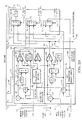
- FIG. 1 is a representation in block diagram form of one embodiment of a video effects system according to the present invention.
- FIG. 2A and FIG. 2B are a representation in block diagram form of another embodiment of the video effects system according to the present invention.
- FIG. 3 is a drawing of a typical frame of special effect processed video to illustrate some of the teachings of the invention.
- An input video signal V ′ 1 is received at an input 10 and is coupled through a video channel 12 which includes a gain adjusting device, such as multiplier 14, to a first summer 16 sometimes also referred to herein as the output combiner.
- the output combiner is the combination of the gain adjusting devices 14, 32 and 40 (sometimes hereafter referred to as cutters) and the summer 16.
- a composite video signal V" is coupled out of the video system via an output 11.
- the multiplier 14 adjusts the gain of the video signal V ′ 1 according to the value of an input key signal K A presented on line 18 to the control terminal of the multiplier 14.
- the video data on bus 12 comprises, in the preferred embodiment, a stream of digital data that defines the pixel color and intensity of all the pixels on each raster line of each field and frame of picture information.
- Each frame of picture information is comprised of two fields of raster lines one of which has 262 lines and the other of which has 263 lines (NTSC only; PAL format video is different).
- the multiplier 14 receives a key signal K A for each pixel, i.e., the value of K A is updated for each pixel.
- the value of K A is multiplied in multiplier 14 by the pixel data to which it applies arriving from terminal 10 and the resulting data is output on bus 12.
- the gain adjusting device 14 would be some analog circuit which could perform the analog version of a multiply operation in digital processing.
- the system of Figure 1 basically provides three video sources to an output summer 16 where the three streams of video data are combined in various proportions established by the various key signals to form the output video signal V" on bus 11.
- image 1 data main video which may sometimes hereafter be referred to as image 1 data
- image 2 data a source of recirculation video data on bus 13 coupled to the output of a gain modifying device 32 which may sometimes hereafter be referred to as image 2 data.
- the third source of video data is background video which may sometimes hereafter be referred to as image 3 data.
- the gain modifying device 32 may be a multiplier.
- the recirculation video data is generated in a recirculation loop 15 which has the capability of receiving video data, storing it in a framestore 28 for one field or one frame and then recirculating it for reinput to the framestore either alone or combined with new video data.
- the recirculation loop 15 is structured as follows.
- the input video signal V′ is coupled through a second video channel 20 to another control device, such as multiplier 22, which adjusts the level of the video signal V′ in accordance with a key signal K B presented on a line 24 to the control terminal of a gain modifying device 22.
- the device 22 may be a multiplier.
- This gain adjusted video information is then presented to the recirculation loop 15 consisting of a second combiner, sometimes hereafter referred to as a recirculation combiner and consisting of the cutters 22 and 30 and the summer 26, and a storage device 28, sometimes hereafter referred to as a framestore.
- the framestore 28 is of sufficient size to retain a full frame of video information including both fields.
- the recirculation loop includes a gain modifying device 30.
- the latter is connected between the output of the framestore 28 and one input of the summer 26.
- the other input of the summer 26 is coupled to the output of the gain modifying device 22.
- the video data on line 29 can have a gain anywhere from 0 to the maximum available resource.
- the multiplier 30 adjusts the gain of the recirculating video information presented to the second summer 26 in accordance with a key signal K C presented via the line 31 to its control terminal.
- Video information is coupled out of the recirculation loop via a control device, such as multiplier 32. This device adjusts the gain of the video information presented to the output summer 16 in accordance with a key signal K D presented via the line 34 to its control terminal.
- One or more additional video channels such as represented by a video channel 36 may be provided and will include an input 38 for such additional video information.
- this video information will be background video and may sometimes hereafter be referred to as image 3 data.
- This video information is then coupled via a control device such as a multiplier 40 to an input of the output summer 16.
- the level of the video information coupled therethrough is adjusted in accordance with a key signal K E presented to the control terminal of the multiplier 40 on the line 42.
- a video signal is preferably composed of discrete digitally encoded video samples related to separate pixels that collectively define the video image.
- each pixel may be comprised of a plurality of different components, such as a single luminance and a pair of chrominance components, each having an independent level but each having the same gain.
- each video pixel will have a corresponding key signal, and each key signal may have a value of between zero and one for each pixel of video information. That pixel key signal is applicable to all signal components corresponding to that pixel.
- the control devices are multipliers
- a video signal is processed by multiplying its input value with that of its corresponding key signal to produce a resultant instantaneous value at the output summer 16.
- a key processor 44 calculates a key signal for each multiplier in the video channels. For example, one set of conditions for a key signal is a value of either zero or one. If a video signal is multiplied with a key signal having a value of zero, the resulting video signal would have a gain of zero, which is the absence of a video image. If a video signal is multiplied by a key signal that has a value of one, the value of the resultant video signal is unchanged and would be viewed on a monitor as unchanged.
- the video signal can be multiplied by a key signal having a value of between zero and one.
- the effect of multiplying the video information with a number reducing from one to zero is to give the resulting raster of video an increasingly transparent appearance, because video from another source can then be added to the raster such that the other video appears to be increasingly visible through the video which has been so processed.
- the key signal value is reduced to zero, the processed video will no longer be visible.
- the key processor 44 it is necessary for the key processor 44 to adjust the value of the key signals in the system to assure that the sum of the key signals is not greater than one.
- the system of Figure 1 is capable of operation in either a field mode where both fields of data are updated during every field or a frame mode where each field is updated as it arrives where each field arrives separately and sequentially,
- the field mode the assumption is that the pixels of field B will be set equal to the corresponding pixels in field A as the field A pixels arrive. Further, the field A pixels will be set equal to the corresponding field B pixels as the field B pixels arrive.
- the addressing circuitry 17 and the store 28 combine to provide one field delay. This delay is between the arrival of pixel data from one field and output of the same pixel data as the recirculation video pixel data for the next field which is simultaneously arriving at input 10.
- the addressing circuitry 17 and the store 28 combine to provide a one frame delay.
- the video pixel data for both fields A and B arriving at input 10 is stored in store 28 as it arrives.
- the video pixel data from the previous frame (e.g., frame 1) stored in the store 28 is output on bus 23 as the recirculation video pixel data for the current frame (e.g., frame 2). That is, for example, as pixel 1 of line 1 of frame 2 arrives at input 10, store 28 and addressing circuitry 17 combine to output pixel 1 from line 1 of the previous frame, frame 1 on bus 23.
- Addressing circuitry 17 provides the necessary address signals on the bus 19 to implement either mode in accordance with a mode control signal on a line 21.
- the basic purpose of the recirculation video store 28 is to provide a delay of either one field or one frame between the storage of video information from bus 29 and outputting of the same video on bus 23 either one field or one frame later.
- the addressing circuitry makes this possible by generating the proper address signals and control signals on the bus 19 to make the proper delay happen in accordance with a mode control signal on the line 21.
- the addressing circuit 17 generates addresses continuously and sequentially by counting in synchronization with the pixel data as it arrives.
- the addressing circuitry presents the address where the data defining each pixel is to be stored in the framestore 28 as that pixel data arrives.
- the addressing circuitry counts up to the end pixel address on raster line 262 for field 1, and then resets to 0 (NTSC only). For the next field, the counter counts up to the last pixel address on line 263 and resets to 0 (NTSC only). In the frame mode, the counters in the addressing circuitry count up to the last pixel in line 525 (NTSC only) before resetting to 0 and starting to count up again.
- the addressing and storage of data in the framestore results in a delay between the input of the video data and the readdressing of that data and presentation of that data at the output 23 of the framestore. It is this delay which allows certain special effects such as trails to be performed. The delay can be altered by changing the mode signal.
- the field interpolation algorithm used in the system just described worked as follows. Assume the first field in a frame is called A and is comprised of raster lines A1 through A262 and the second field in the frame is comprised of raster lines B1 through B263.
- the field interpolation circuit interpolates the first pixel in line B1 by adding 1/2 of the value of the first pixel in line A1 to 1/2 of the value of the first pixel in line A2. This process is repeated for each pixel using the values of the pixels directly adjacent to it in the opposite interlaced field.
- the output of the framestore 28 will be the pixel data of field B of the previous frame as the pixel data of the current field B is arriving.
- the old data is output on the bus 23 and the new data of the current field B is written into the framestore. This provides continuous updating of the video data in the frame store. Since the video data coming out of the frame store has been delayed by either one frame or one field depending upon the operation mode, special effects such as trails may be performed by mixing the framestore output on bus 23 with the current video on bus 12.
- a trail is a series of images shown simultaneously with the image showing a moving object's current position.
- the series of images show the previous positions of the object.
- Cutter 14 has its key signal K A manipulated on a pixel by pixel basis to be 1 at every pixel defining the baseball's current position and 0 at every other pixel.
- the key signal K A arrives on line 18 from some external circuitry which is not part of the invention.
- the key K A may itself be cut by an input transparency key supplied on line 25 by circuitry which is not part of the invention.
- the trail images are supplied by continuously updating the contents of the framestore 28 with new video via the bus 20 and the cutter 22.
- the key signal K B is manipulated on a pixel by pixel basis to allow the video data defining the current position of the baseball to be supplied at the input 25 of the summer 26.
- This video data is combined with the recirculated video on bus 27 which defines the former positions of the baseball by virtue of the delay imposed by the framestore.
- Each new update of the framestore 28 adds a new image to it.
- the images in the framestore of the baseball's former positions may be made to decay at any desired rate by manipulating the key K C such that the recirculation video pixel data is multiplied by a factor between 0 and 1 on each recirculation.
- a key processor 44 generates the key K C as a function of the key K B so that the combination of the recirculation video on bus 27 and the update video on bus 25 does not result in a combined video signal on bus 29 which has a gain greater than 1 or the maximum allowable system gain. How the key processor does this will be described in more detail below.
- the output of the framestore 28 on line 23 is video data which describes the former positions of the baseball.
- This video data is applied to the output summer 16 via the cutter 32 and bus 13.
- the key K D is manipulated on a pixel by pixel basis to allow the recirculation video data defining image 2 of the former positions of the baseball to be combined with the image 1 data on bus 12 defining the current position of the baseball so that the composite output video at terminal 17 does not exceed the maximum allowable gain at any pixel location.
- a background image 3 such as an image of homeplate may also be combined with the image 1 and 2 data via the background video bus 38 and the cutter 40.
- This background video is cut by a key K E which is manipulated as a function of the other keys K A and K B so that the composite video output at terminal 17 does not exceed the maximum allowable gain at any pixel location.
- the trail images can be made to disappear and reappear simply by proper manipulation of the key K D .
- the trail images can be made to disappear by reducing the key K D to 0. Since doing this does not destroy the video data in the framestore 28, the trail can be made to reappear by causing the key K D to assume any non zero value between 0 and 1.
- the key processor 44 in Figure 1 can be any circuitry or software/hardware combination that manipulates the key signals described above in the manner described above to perform the special effects described herein or any other special effects which the system is capable of performing.
- FIG. 2 there is seen a second embodiment of a video effects system according to the teachings of the present invention.
- This second embodiment is similar to the first embodiment shown in FIG. 1 except that the key processor 44, shown in phantom in Figure 2, comprises a memory key processor 50, an output key processor 52, and a multiplexer 54.
- the memory key processor 50 and the output key processor 52 have structures which are similar to the channel A and B key processors described in patent application "A Recirculating Special Effects Video Framestore", EP-A-0 221 926. More details on the structure and operation of the key processors will be given below.
- An input key signal K I representing the requested key for the image 1 video arriving at the input 10 is presented at an input 18 and is coupled to the inputs of gain adjusting devices (multipliers or cutters) 60 and 62 in the memory key processor 50 and the output key processor 52 respectively.
- Each of the cutters 60 and 62 receives a transparency factor signal on lines 64 and 66, respectively.
- the cutter 60 receives a memory transparency factor signal on the line 64 which acts to cut the K I key to whatever level of transparency is desired for the image 2 data being written into the recirculation video framestore 28.
- the result of the operation of the cutter 60 is output as the K B key on line 24 to the cutter 22 to reduce the gain of the video on line 20 to some new level on line 25.
- the cutter 62 receives an input video transparency factor signal on the line 66 and cuts the key K I appropriately and outputs the result as the K A key on line 18 to the cutter 14.
- This cutter alters the gain of the incoming video of image 1 at the terminal 10 to the desired gain level of the image 1 video on line 12 coupled to a first input of the output summer 16.
- the image 1 video has the highest priority and other key in the system are processed to have the appropriate levels so that the image 1 video will have the highest priority and the other video sources will have their gain levels adjusted accordingly to make best use of the maximum allowable gain in the system.
- Inputs 46 and 48 are provided for the memory key processor 50 and output key processor 52, respectively, to receive input signals F(x) and F(y), respectively, to control the key processors to produce decay of the video in the framestore 28 or decay of the image 2 video on line 13 respectively.
- This allows "trail”, “reveal” or “layer” (flying image 1 over image 2 without destroying the portions of image 2 over which image 1 passes) special effects to be performed with the image 2 video decaying at any desired rate.
- This decaying can take place either in the recirculation loop 15 by virtue of decay of the video being written into the store 28 or by the action of the cutter 32 with a decaying key K D .
- the signal F(x) controls the rate of decay of the key signals in the internal key recirculation loop of the memory key processor 50
- the signal F(y) controls the rate of decay of the key signals in the internal key recirculation loop in the output key processor 52 as will be described in more detail below.
- Each of the key processors 50 and 52 contain key framestores which store the keys for all the pixels for the last field or frame depending upon whether the system is operating in the field mode or the frame mode. More specifically, memory key processor 50 contains a key framestore 68 with one key storage location for every video pixel data storage location in the recirculation video framestore 28. The key for each video pixel in the framestore 28 is stored in a corresponding memory location in the key framestore 68 in the memory key processor 50. The key for each pixel in the last field or frame of image 1 video is stored in a corresponding key storage location in a key framestore 70 in the output key processor 52.
- Each of the recirculation video framestore 28, the key framestore 68 and the key framestore 70 have the proper number of storage locations to store video pixel data or the key for same in a one to one correspondence with the image 1 pixel data on each raster scan line for the current field of video pixel data being input at input 10.
- Each of the recirculation video framestore 28, the key framestore 68 and the key framestore 70 are sequentially addressed by addressing circuitry to address the storage locations corresponding the current pixel and the current raster line of the image 1 video.
- the addressing circuitry for the key framestore 68 and the key framestore 70 is not shown in order to not unduly clutter the drawings, but it is similar to the addressing circuitry 17 of the recirculating video framestore 28.
- a signal RECIRC. REQ. representing the value of the "requested" key for the currently addressed pixel in the recirculation video framestore 28 is coupled from the memory key processor 50 via the line 53 to the output key processor 52.
- the RECIRC. REQ. signal is taken from the output bus 72 of the key framestore 68 since the output data there always represents the key of the corresponding pixel stored in the recirculation video framestore 28 which is currently being read on the bus 23. This data is used in a normalization process which will be described more fully below.
- the multiplexer 54 receives the processed key signals from the memory key processor 50 and the output key processor 52.
- the multiplexer 54 includes 3 separate 2 input/1 output multiplexers 74, 76 and 78 which each receive switching control signals that define certain modes of operation for the embodiment shown in Figure 2.
- Key signals for the cutters 32 and 40 as well as an output key signal at the output 56 for use by an external processing device, such as a video production switcher are taken from the outputs of the three multiplexers.
- a key signal generated by a ratio calculation circuit 80 in the memory key processor 50 preferably is always connected to provide key signal K C to control processing of the recirculated video by the multiplier 30.
- the key K C is coupled to one input of the multiplexer 76 so that it can be used, for example, as key signal K D to control the multiplier 32 during "external key” modes of operation as will be explained more fully below.
- a key signal generated by a ratio calculation circuit 82 in the output key processor 52 is coupled to one input of the multiplexer 76, from which it may be transmitted over line 34 to control the multiplier 32 as the key K D during normal modes of operation.
- the multiplexer 74 and a summer 84 in the memory key processor provide the necessary processing to produce key signal K E to control the multiplier 40.
- This multiplier 40 permits background video to be input on bus 37 to the output summer 16 if desired when the sum of K D and K A is less than one.
- the structure and operation of the output key processor are as follows.
- the function of the output key processor will be explained in the context of performance of the "reveal" special effect.
- image 2 video is trapped in the framestore 28, and the image 1 data is blocked by the K B key from updating the framestore 28 so no image 1 data is written over any image 2 data in the framestore 28.
- the reveal effect is the appearance of image 2 data in the path of a moving image 1 object. For example, assume image 1 is a baseball moving across the screen from left to right, and image 2 is a stationary picture of a white home plate sitting in brown dirt. The reveal effect will be display of the image 2 video in the path of the moving baseball.
- the path of the baseball will show brown dirt until the baseball passes over the plate at which time the path of the baseball will be filled with the white pixels of the picture of homeplate. If the pitch only catches a corner of the plate, some of the pixels in the baseball path will be white and some will be brown.
- the output key processor to manipulate the key K D such that for all pixels in the path of the baseball but not including the pixels defining the current position of the baseball, the key K D is non zero thereby revealing the contents of the framestore 28 at those pixel locations.
- the image 2 video must be written into the framestore 28 and frozen there.
- the picture of homeplate is supplied as video data to terminal 10.
- the MEMORY TRANSPARENCY FACTOR signal on line 64 is held at 1 and the key K I on line 18 is driven in accordance with the image 2 video data.
- the input key K I then passes through the cutter 60 and becomes the key K B on line 24 during the process of trapping the image 2 video in the framestore 28.
- the MEMORY TRANSPARENCY FACTOR signal on line 64 is set to zero until the reveal effect is completed. This prevents further updating of the framestore by cutting the K B key to 0.
- the key for each pixel of image 2 is simultaneously written into the key framestore 68. This occurs because the K B key on line 24 is added by a summer circuit 88 and output on line 90 to the data input of the key framestore 68.
- the summer 88 adds the key on line 24 to a key signal on line 92 which is derived as follows.
- a key space available circuit 94 calculates the quantity (1 - K B ) and outputs same on line 96. This quantity is coupled to one input of a minimum calculating circuit 98. Another input of the minimum calculating circuit is coupled to a key signal on line 100. This key signal is the output of an F(x) calculating circuit 102 which is a gain modifying device such as a multiplier.
- This circuit functions to receive the F(x) signal on line 46 and use it as a key to control how much gain reduction is applied to a key signal on the line 72 before outputting same as the key signal on the line 100.
- the key signal on the line 72 is the key signal stream for the pixels currently stored in the recirculating video framestore 28.
- the minimum calculating circuit 98 calculates which of the key signals on the line 96 and 100 is the smaller and outputs the smaller key signal on the line 92.
- the key on the line 92 is added to the key on line 24, and the sum is written into the key framestore 68.
- the key on the line 92 is also input to one input of the ratio calculating circuit 80. The other input of this circuit is coupled to receive the key signal on the line 72.
- the ratio calculating circuit 80 calculates the ratio of the key signal on line 92 as the numerator to the key on the line 72 as the denominator. This ratio is used as the key signal K C on line 31 to control the cutting action of the cutter 30 controlling the gain of the recirculated video on line 27.
- the image 1 or input video key KI is cut by a transparency cutter 62 which receives a signal INPUT VIDEO TRANSPARENCY FACTOR on line 66 that controls the transparency factor of the image 1 video on bus 12.
- the output of the cutter 62 is the K A key signal on line 18.
- This key signal is also coupled to one input of a summer 106 which has its output coupled as the external key output 56.
- This external key signal output is also coupled to one input of the multiplexer 74 and to one input of the multiplexer 78.
- the output of the multiplexer 78 on line 108 is coupled back into the data input of the key framestore 70 for the image 1 video.
- the data output of the key framestore 70 on line 110 is coupled to the input of a cutter 112 designated the F(y) circuit.
- This circuit receives the F(y) signal which controls the rate of decay of the recirculating keys for the image 1 video that are stored in the key framestore 70. If the signal F(y) is less than 1, the stream of key signals on line 114 will have the gain of each key cut by the amount set by the signal F(y). The resulting key signals are output on line 114 and are coupled to one input of a minimum calculating circuit 116.
- the line 114 is also coupled to one input of the multiplexer 78 so that the layer effect may be implemented as will be explained in more detail below. In this effect image 1 is "flown" over image 2 without destroying image 2.
- the only other circuits in the output key processor are the key space availability calculation circuit 118 and the ratio calculation circuit 82. The operation of these circuits will be explained next in the description of how the memory key processor 50 and the output key processor 52 function to allow various special effects to be performed
- the purpose of the memory key processor 50 is to generate the key signal K C as a function of the key signal K B to insure the the output of the summer 26 does not have a gain greater than the maximum available resource.
- the relationship between the maximum available resource and gain is such that a signal that is a composite of two or more video signals that can have gains between x volts and y volts also has a gain, i.e., a maximum signal excursion from x volts to y volts.
- the combined video signal will not have a gain of 0.8 at that pixel location. Instead, the gain of the combined pixel will depend upon the relative transparency factor of each pixel and which pixel has priority. This will become more clear in connection with the discussion of the functioning of the ratio calculation circuits 80 and 82. Also, recall that the overall purpose of the output key processor 52 is to generate the key signal K D as a function of the key signal K A so that the final composite video at the output 17 of the summer 16 does not have a gain greater than the maximum available resource.
- FIG. 3 shows the path of a moving baseball during two successive frames of image 1 video on line 12.
- the baseball at location 126 in frame 1 has a stream of key signals K A which are 1 (or less than 1 if the signal INPUT VIDEO TRANSPARENCY FACTOR is less than 1) for the pixels in the circular area of the frame within the perimeter of the baseball at location 126. All pixels outside this have a key signal of 0.
- K A key signals
- All pixels outside this have a key signal of 0.
- the baseball has moved to the location shown at 122.
- the pixels inside the circular area bounded by the perimeter of the baseball at location 122 have key signals K A of 1 and all pixels outside this area have key signals K A of 0. Again these key signals K A from frame 2 are written into the key framestore 70 via lines 107 and 108.
- the key signals K A from frame 2 inside the perimeter of the baseball at location 122 overwrite the key signals K A from frame 1 inside the perimeter of the baseball at the location 120 in the key store 70.
- the key signals in the key storage memory locations corresponding to the pixels in the overlapping cross hatched area 125 will be whatever the key signals K A were for the baseball at location 122.
- the 0 keys K A corresponding to the pixels located outside the baseball location at 122 in frame 2 do not overwrite the key signals K A having a value of 1 inside the baseball at the location 120 in frame 1 because of the operation of the circuitry of the output key processor.
- the key signal K A for a pixel shown at 126 has a value of 0 during frame 2 in Figure 3 and is arriving during frame 2 on line 18 of the output key processor.
- the key space availability calculation circuit 118 outputs a 1 on line 128 coupled to the minimum circuit 116. This minimum circuit also receives a key signal on line 114 from the F(y) cutter 112 which represents the "key requested" and which is actually the key value for pixel 126 during frame 1.
- this key value is written into the storage location for pixel 126 in the key framestore 70 via the multiplexer 78 and the line 108 during the normal mode of operation.
- the key framestore 70 collects the key values for all the pixels locations where the baseball has been as it moves across the screen. It is in these pixel locations that the video from image 2 stored in the framestore 28 must be displayed.
- the system works the same when the F(y) function cuts the key signal on the line 110 except that there is a decay in the value of the key signals stored in the key framestore 70 so that the trail fades away.
- the minimum determining circuit 116 does not receive two 1's on lines 116 and 114. Assume that the key requested has been cut from 1 on line 110 to 0.8 on line 114. The minimum calculation circuit 116 then outputs a "key received" signal on line 130 of 0.8. This key signal is added to the 0 key on line 18 and output on line 107 for reinput to the key framestore 70.
- the key signal on line 107 does not go to the cutter 32 as the K D key signal because the recirculation video stored in the framestore 28 has already been previously cut by other key signals such as K C and K B .
- the key signal on line 107 cannot be used directly as the key signal K D since the image 2 video coming out of the framestore 28 may have already been cut to the desired value on line 107 or some value less than 1 but greater than the cut required by the key signal on line 107.
- the ratio calculation circuit 82 is used. This circuit receives the key signal on line 53 which indicates the amount any particular pixel stored in the framestore 28 has already been cut.
- the other input on line 130 is the desired gain level in the form of the "key received”.
- the ratio of these two signals i.e., "key received” on line 130/"key of recirculation framestore pixel" on line 53, is used as the K D key signal to cut the recirculation video on the line 23 to the correct gain level on line 13.
- the key signal on line 130 would be 0.5 (this key always represents the calculated gain for the video on line 13 to insure that the sum of the gains of the video on lines 12 and 13 is always 1 or less). Therefore, no further cutting would be required by the cutter 32 since the gain of the recirculation video emerging on line 23 is already at the desired gain level for the video on line 13.
- the output of the ratio calculation circuit 82 would be 0.5/0.5 or 1 for the K D signal thereby allowing the video on line 23 to pass uncut through the cutter 32 so that the video on line 13 would have the desired gain of 0.5.
- the key K D would have to be 0.5 to cut the 0.5 gain video on line 23 to a gain of 0.25.
- the key signal on line 53 would be 0.5 corresponding to the gain of the pixel on line 23, and the signal on line 130 would be 0.25.
- the ratio of the two would be 0.5 for the signal K D .
- the memory key processor does the same type of operation as described above when new video is being written into the framestore 28.
- the key signal on line 96 will be the key space available for the video on line 27 based upon the gain taken by the higher priority new video pixels arriving on line 25. That is, the key signal on line 96 represents the most gain available to the signal on line 27, and therefore the maximum key signal K C available based upon the value of the K B signal.
- the key signal on line 100 represents the recirculation video gain requested, i.e., the present gain of the image 2 pixel then present on line 23 at the input of the cutter 30.
- the minimum calculation circuit 98 determines the minimum of the two key signals on lines 96 and 100 and outputs same on line 132.
- the key signal on line 132 represents the percentage of the total available resource at the output combine which is available to the image 2 pixel in the framestore.
- the key signals on lines 132 and 24 are then added by summer 88 to determine the key signal to be stored in the key framestore 68 for the current frame.
- the ratio calculating circuit 80 is present to insure that in the case the key of the image 2 pixel coming out of the framestore 28 at line 23 is already at the desired gain level specified by the key signal on line 132 or at some gain level between the desired gain and 1, that only the appropriate level of cutting is performed at cutter 30 via the K C key to obtain the desired gain level for the recirculation video at line 27.
- the ratio calculating circuit calculates the ratio of the key on line 132 to the key on line 72 representing the key of the video on line 23 to determine the correct value for K C .
- the gain of the video on line 23 is 0.7 and the key K B is 0.4
- the key space available on line 96 is 0.6
- the key signal on line 100 is 0.7.
- the minimum calculation circuit determines that the maximum gain available for the video on line 27 is 0.6 which is less than the current gain of the video on line 23 at 0.7 so a cut at cutter 30 must be made.
- the ratio calculating circuit then outputs a key signal K C of 0.6/0.7 which when multiplied by the video on line 23 having a gain of 0.7 results on a gain on line 27 of 0.6 which is the desired gain there to have a gain for the video on line 29 of 1 or the maximum available resource.
- the resulting key written into the key framestore 68 for this pixel is 1 on line 90 by the action of the summer 88 adding the 0.6 key on line 132 to the 0.4 KB key on line 24 thereby accurately representing the key for the corresponding video pixel stored in the framestore 28.
- the multiplexers in the switching matrix 54 serve to control the mode of operation of the system.
- the composite video at the output 11 is often coupled to a video switcher. It is an assumption in the design of most present video switchers that the video coming into the switcher is always at gain equal to 1 and the switcher will then multiply the video down to the appropriate gain using a key supplied to the switcher for the incoming video. This external key function is the reason for the output 56.
- the multiplexer select line 107 for coupling to a key space available calculation circuit 134 during normal mode operations.
- the key signal on line 107 is always equal to the gain of the video on the recirculation video input path 13 plus the gain of the video on the image 1 video path 12 to the output summer 16.
- the key signal K E on line 42 is always equal to 1 - (K A + K D ).
- the external key on line 56 to the switcher is only the sum of the key signals K A and K B , i.e., the key signal on line 107.
- the switcher design is based upon an assumption that only the gain of the image 1 and image 2 recirculation video is in the external key signal and no background gain is included.
- the multiplexer 76 receives a switching control signal on line 138 which causes the line 140 to be selected and coupled to the line 34 as the key signal K D . This causes the images in the image 2 video, i.e., the trail images to slowly fade away.
- the switching control signal in the line 138 causes the multiplexer 76 to choose the line 142 for coupling to line 34 as the K D key.
- This coupling causes the non decaying key signal on line 142 to be applied to the cutter 32 as the key K D .
- the video on line 13 is not decaying but the external key on line 56 is decaying so that the switcher coupled to line 11 may properly decay the combined video on line 11 according to the key on line 56.
- the key K E must also be altered so that the background video does not get out of proportion.
- the multiplexer 74 selects the key signal on the line 144 for coupling to line 42 as the K E signal.
- the key signal on the line 144 is the sum of the "key received" on line 132 calculated by the memory key processor and the key K A .
- the "layer" effect where image 1 flies over a frozen image 2 stored in the framestore without destroying image 2 involves the operation of the multiplexer 78.
- the multiplexer 78 selects line 114 for coupling to the line 108.
- the memory key processor is operated to freeze the video trapped in the framestore 28 without updating it with new video from line 20. This is done by setting the MEMORY TRANSPARENCY FACTOR signal on line 64 to 0 to cause the cutter 22 to block any video from line 20 from entering the summer 28.
- Causing the multiplexer 78 to select the key signal on the line 114 causes the key requested signal on line 110 at the output of the key framestore 70 to be recycled back into the input of the key framestore 70 after passing through the F(y) cutter 112.
- the F(y) cutter 112 passes the key signals on line 110 through to the line 114 uncut.
- This looping connection holds the keys in the key framestore 70 steady so that there is no updating. This prevents the swath of non zero key signals representing pixels where a moving object in image 1 on line 12 has been from being stored and maintained in the key framestore as it was done on reveal.
- the K D key is calculated based only upon the key signals K A for the current position of the moving object in image 1. This means that the recirculation video of image 2 will be visible at all places on the screen except where the moving object is currently located. The image 2 video will even show through the image 1 video if the INPUT VIDEO TRANSPARENCY FACTOR signal on line 66 is set to make the image 1 video transparent.
- video can be stored in store 28 by setting K B and K C to one until the desired video is stored and then setting K B to zero while maintaining K C at one. In this manner, the same video information will be circulated uncut. However, if K D is set at zero, this video information will not be passed to the summer 16. Instead, K E can be set at one, whereupon background video input at 38 will be transmitted in the absence of video input V I ′, because, in the preferred embodiment, the key processor is controlled to give first priority in setting key signal values to input video V I ′, then to recirculated video and then to background video.
- K D can be no greater than 1-K A and K E can be no greater than 1-(K D + K A ).
- the current algorithm implemented by the key processors is to calculate the key received, i.e., the key signals on lines 130 and 132, as the minimum of either the key requested (the key signals on lines 110 and 72, respectively) or the key available (the key signals on line 128 and 96, respectively).
- the key received for each image 2 video pixel could be calculated by multiplying the key requested for each image 2 video pixel times the key available, i.e., the quantity 1 - K A , where K A is the image 1 video pixel key for the same pixel.
- the embodiments described above may be implemented in software on a general purpose computer. Both real time and non real time embodiments in pure software may be implemented.
- the cutter 22 may be deleted and a simple switch substituted. When the switch is open, no updating of the video in the framestore 28 occurs which is the state the system must be in to perform reveal and layer effects. When the switch is closed, the framestore is updated with video from line 20 and effects such as trails may be performed.
- timing of addressing and performing the read and write cycles for the various framestores and key framestores in the embodiments described herein must be matched to the pixel data rate of the raster scan.
- One way this can be done is by using shift registers and reading and writing a plurality of pixels at a time in parallel load and unload operations while shifting pixel data into or out of the shift registers at the video pixel scanning rate.
- account must be taken in the key processors for the delays involved in processing in the key recirculation loops described herein.
- One way of doing this is reading and writing addresses in the key framestores non sequentially. In other words, because of timing considerations related to circuit delays, it is desirable to read blocks of data at particular times and write blocks of data to these same addresses at later times to accommodate circuit delays. Those skilled in the art will appreciate how these timing considerations can be accommodated.
Landscapes
- Engineering & Computer Science (AREA)
- Multimedia (AREA)
- Signal Processing (AREA)
- Studio Circuits (AREA)
- Closed-Circuit Television Systems (AREA)
Abstract
Description
- This invention relates generally to video systems for the creation of a variety of special effects and, more particularly, to a video system in which separately calculated key signals are employed to adjust the gain of input video signals, recirculating video signals and output video signals presented to an output combiner so that a composite video signal can be formed therefrom.
- In the television industry there is an ongoing desire to combine video signals in a variety of ways to create various special effects. For example, a common function of a digital video effects system is to compress a full field of video to a size smaller than the raster area occupied by a full size field of a television signal. The smaller raster is then displayed at a predetermined location within the larger raster of video.
- Framestores recently have been developed for use in the video industry to store video information for the creation of special effects. Such devices typically include a memory device capable of holding at least one complete raster of video information, i.e., either a field or a complete frame of video information. One such framestore system is described in EP-A-0221926 (published as WO 86/06233), which discloses features corresponding to the precharacterising parts of each of the independent claims of the present application.
- In creating special effects, digital video signals are typically combined through the use of key signals. Two unprocessed video signals cannot be directly combined because the combined signal gain would be the sum of the initial gains of each unprocessed video signal and could exceed the maximum gain resource of the system, i.e., the combined video signal can have a maximum gain no larger than the maximum gain of any of the component video signals. Thus, if all component video signals in the system are allowed to vary in gain anywhere from 0 to 1 volt, the maximum gain excursion of a composite video signal consisting of a combination of two or more component video signals can be no more than from 0 to 1 volt. The key signals are used according to the teachings of the invention to cut the gain of component video signals according to calculations relating to the transparency factor of each signal, the maximum available gain for the composite signal and the priority of the various signals. By using separate key signals for each video signal, the key signals can be independently processed to control the gains of the component video signals in such a manner that the final composite video signal uses all the available gain resource without the injection of spurious noise. That is, prior to combining video signals, each individual video signal is gain adjusted by its respective key signal in such a manner that the composite video signal does not exceed an overall reference gain which is the maximum allowable gain resource available to any video signal in the system. A more complete understanding of key signals in video signal processing can be obtained from European Patent No. EP-A-0217938 (published as WO-86/06234).
- Another device used in video effects systems is a combiner which is a device to do a "combine" of two or more video signals. A "combine" is effected by combining two or more channels of video information in such a way as to make the scenes or images appear in a desired relationship with each other, e.g., one in front of the other, a transparent image, one image flying over another, one image moving and leaving a trail, etc. One such combiner is illustrated, by way of example in EP-A-0160549.
- In the video effects system described in the above identified EP-A-0221926 video information is held in a memory sometimes hereafter referred to as a framestore or store and is recirculated. This recirculated video is combined with new or input video information in a combiner during recirculation. The recirculated video is processed or "cut" by a key signal in a controllable manner during each recirculation to reduce the gain of the signal. This cut allows combining the recirculated video signal with other videos having a known gain to produce desired video effects in the form of an output video signal having a gain which does not exceed the system's maximum allowable gain. It is a limitation of such a system that once video information in the store has been processed or cut by the key signal during recirculation, the lost gain cannot be restored since to increase the gain of a video signal by multiplying it by a value greater than 1 only adds noise since there is no new video information in the multiplication operation. Thus, the cut video information is recirculated back into the frame store and overwrites the video information stored therein. The video information that existed before the cut is therefore forever lost. This is disadvantageous since it is desirable for certain special video effects to be able to make the recirculated video information from the framestore appear at various gain levels, disappear and then reappear at any gain level compatible with the maximum allowable system gain.
- In one aspect the invention provides a video effects system comprising a video recirculation loop including a storage means for storing a video signal received at an input of the storage means from an output of an input combiner and for providing the stored video signal at an output of the storage means as a recirculated video signal at a later time, the input combiner being arranged for combining the recirculated video signal with a first input video signal from a video source, into a combined input signal for the input of the storage means, the input combiner including means for adjusting the gains of the first input video signal and the recirculated video signal within the combined input signal in accordance with a first video key signal and a recirculation key signal respectively; characterised in that the system further comprises an output combiner for combining the recirculated video signal with another video signal, in proportions represented by an output key signal and a second video key signal respectively, into an output video signal, the output combiner including means for adjusting the gains of the recirculated video signal and the said another video signal within the output video signal in accordance with the output key signal and the second video key signal respectively; and key signal processing means for generating the recirculation key signal and the output key signal such that the gain of the recirculated video signal within the combined input signal and the gain of the recirculated video signal within the output video signal respectively can be separately adjusted in the input combiner and in the output combiner respectively.
- In another aspect the invention provides a method of combining video signals, comprising applying to a video input of a storage means a combined input signal comprising an input video signal and a video signal recirculated after a delay from the output of the storage means and adjusting the gains of the input video signal and the recirculated video signal within the said combined input signal in accordance with corresponding key signals; characterised by combining the recirculated video signal with another video signal into an output video signal; adjusting the gains of the said recirculated video signal and the said another video signal within the said output video signal in accordance with respective key signals; and generating the key signals for the said recirculated video signal such that the gain of the recirculated video signal within the combined input signal and the gain of the recirculated video signal within the output video signal can be separately adjusted.
- The video effects system according to the present invention provides a video system with enhanced special effect capabilities through the use of two combiners, one at the input of the recirculation loop and one at the output of the recirculation loop. The strategic placement of five different "cutters" throughout the system including one between the output of the recirculation loop and the output cutter and the use of separate key signals calculated for each combine function allow great flexibility in the types of special effects that may be achieved. A "cutter" is a gain modifying device such as a multiplier which can reduce the gain of a digital pixel of video information by multiplying the digital value representing the gain by a digital number multiplier representing a key signal corresponding to that pixel.
- Some of the special effects which may be achieved according to the teachings of the invention cannot be performed by prior art systems. Two key processors in the preferred embodiment provide independent control of certain key signals as a function of certain other key signals to prevent the maximum gain resource of the system from being exceeded and to provide optical correctness. The key processors calculate the keys or multipliers so that the composite video signals have a maximum gain which is not more than the maximum allowable gain of any component video signal which is equal to the maximum allowable gain of the system in accordance with certain rules of priority and in accordance with the desired gain or transparency value desired for each signal component of the composite video.
- In accordance with this invention, a recirculation loop is provided to store and recirculate video. This recirculated video information is processed by a memory key signal during each recirculation prior to being combined in a video combiner coupled to the input of the recirculation loop. The recirculation video so processed is then combined with new input video information to be written into the framestore which itself may be cut by a key signal. In addition, the video information output by the framestore is processed by an output key signal and is combined with input video at an additional output video combiner. The use of a separate output key signal and memory key signal allows the recirculation video to disappear and reappear in the output video from the output combiner. The two key signals, i.e., the memory key signal and the output key signal are separately processed so that the output video may be different from the recirculated video held in the framestore. Accordingly, it is possible to process or cut the output video from the framestore to fade the video image from the recirculation video and then make it reappear. Further, is it possible to cause the recirculation video to have a variable amount of apparent transparency by controlling the output key signal while maintaining the video in the framestore uncut.
- In one embodiment, the output key and the memory key are processed by separate key processors which are coupled to the appropriate cutters through a multiplexer. Each key processor generates the appropriate key signal as a function of another key signal indicating the key space available. Key space available is the amount 1- K where K is the key taken previously on the signal with which the signal being processed is to be combined and 1 is the reference gain representing the maximum gain permissible in the system. This enables each key processor to adjust the key being generated by the key processor to compensate for processing already performed by the controlling key signal. For example, the memory key is processed as a function of the key taken on the new input video being supplied to the memory combine at the input of the recirculation loop so that the output video from this combine does not exceed the reference gain. Also, the output key is generated as a function of the key taken on the main video input to the output combine so that the recirculation video being output from the recirculation loop to the output combine has its gain cut to an appropriate value to prevent the output video from the output combine from exceeding the maximum system gain.
- In addition, in an external key mode, it is possible to present a video signal at the output of the output combiner which, at all times, utilizes the maximum available resource in conjunction with an output key signal representing the amount by which the video signal is to be cut by subsequent circuits. The video signal and key signal can then be transmitted to an external processing device, such as a video production switcher, to process the video information in accordance with the key signal.
- Various of the above-mentioned further features and advantages of the video effects system according to the present invention will be apparent from the detailed description appearing hereinafter of one exemplary apparatus and method.
- FIG. 1 is a representation in block diagram form of one embodiment of a video effects system according to the present invention.
- FIG. 2A and FIG. 2B are a representation in block diagram form of another embodiment of the video effects system according to the present invention.
- FIG. 3 is a drawing of a typical frame of special effect processed video to illustrate some of the teachings of the invention.
- Referring initially to FIG. 1, there is seen one embodiment of a video effects system according to the present invention. An input video signal V

input 10 and is coupled through avideo channel 12 which includes a gain adjusting device, such asmultiplier 14, to afirst summer 16 sometimes also referred to herein as the output combiner. Actually, the output combiner is the combination of the gain adjustingdevices summer 16. A composite video signal V" is coupled out of the video system via anoutput 11. Themultiplier 14 adjusts the gain of the video signal V
line 18 to the control terminal of themultiplier 14. The video data onbus 12 comprises, in the preferred embodiment, a stream of digital data that defines the pixel color and intensity of all the pixels on each raster line of each field and frame of picture information. Each frame of picture information is comprised of two fields of raster lines one of which has 262 lines and the other of which has 263 lines (NTSC only; PAL format video is different). Themultiplier 14 receives a key signal KA for each pixel, i.e., the value of KA is updated for each pixel. The value of KA is multiplied inmultiplier 14 by the pixel data to which it applies arriving fromterminal 10 and the resulting data is output onbus 12. In analog embodiments, thegain adjusting device 14 would be some analog circuit which could perform the analog version of a multiply operation in digital processing. - The system of Figure 1 basically provides three video sources to an
output summer 16 where the three streams of video data are combined in various proportions established by the various key signals to form the output video signal V" onbus 11. Besides the main video which may sometimes hereafter be referred to asimage 1 data, there is also a source of recirculation video data onbus 13 coupled to the output of again modifying device 32 which may sometimes hereafter be referred to asimage 2 data. The third source of video data is background video which may sometimes hereafter be referred to asimage 3 data. - In digital embodiments, the
gain modifying device 32 may be a multiplier. The recirculation video data is generated in arecirculation loop 15 which has the capability of receiving video data, storing it in aframestore 28 for one field or one frame and then recirculating it for reinput to the framestore either alone or combined with new video data. - The
recirculation loop 15 is structured as follows. The input video signal V′ is coupled through asecond video channel 20 to another control device, such asmultiplier 22, which adjusts the level of the video signal V′ in accordance with a key signal KB presented on aline 24 to the control terminal of again modifying device 22. As is the case for all the gain modifying devices, in digital embodiments, thedevice 22 may be a multiplier. This gain adjusted video information is then presented to therecirculation loop 15 consisting of a second combiner, sometimes hereafter referred to as a recirculation combiner and consisting of thecutters storage device 28, sometimes hereafter referred to as a framestore. Preferably, theframestore 28 is of sufficient size to retain a full frame of video information including both fields. - The recirculation loop includes a
gain modifying device 30. The latter is connected between the output of theframestore 28 and one input of the summer 26. The other input of the summer 26 is coupled to the output of thegain modifying device 22. The video data online 29 can have a gain anywhere from 0 to the maximum available resource. Themultiplier 30 adjusts the gain of the recirculating video information presented to the second summer 26 in accordance with a key signal KC presented via theline 31 to its control terminal. Video information is coupled out of the recirculation loop via a control device, such asmultiplier 32. This device adjusts the gain of the video information presented to theoutput summer 16 in accordance with a key signal KD presented via theline 34 to its control terminal. - One or more additional video channels, such as represented by a
video channel 36 may be provided and will include aninput 38 for such additional video information. Typically, this video information will be background video and may sometimes hereafter be referred to asimage 3 data. This video information is then coupled via a control device such as amultiplier 40 to an input of theoutput summer 16. The level of the video information coupled therethrough is adjusted in accordance with a key signal KE presented to the control terminal of themultiplier 40 on theline 42. - The
multiplier 14, themultiplier 22, themultiplier 30, themultiplier 32, and themultiplier 40 adjust the gain of the video signals passing therethrough in response to respective key signals. A video signal is preferably composed of discrete digitally encoded video samples related to separate pixels that collectively define the video image. In turn, each pixel may be comprised of a plurality of different components, such as a single luminance and a pair of chrominance components, each having an independent level but each having the same gain. In such systems, each video pixel will have a corresponding key signal, and each key signal may have a value of between zero and one for each pixel of video information. That pixel key signal is applicable to all signal components corresponding to that pixel. As in the present embodiment where the control devices are multipliers, a video signal is processed by multiplying its input value with that of its corresponding key signal to produce a resultant instantaneous value at theoutput summer 16. - A
key processor 44 calculates a key signal for each multiplier in the video channels. For example, one set of conditions for a key signal is a value of either zero or one. If a video signal is multiplied with a key signal having a value of zero, the resulting video signal would have a gain of zero, which is the absence of a video image. If a video signal is multiplied by a key signal that has a value of one, the value of the resultant video signal is unchanged and would be viewed on a monitor as unchanged. - Of course, the video signal can be multiplied by a key signal having a value of between zero and one. The effect of multiplying the video information with a number reducing from one to zero is to give the resulting raster of video an increasingly transparent appearance, because video from another source can then be added to the raster such that the other video appears to be increasingly visible through the video which has been so processed. Thus when the key signal value is reduced to zero, the processed video will no longer be visible. Additionally, because video information from more than one source is being combined in the
first summer 16, it is necessary for thekey processor 44 to adjust the value of the key signals in the system to assure that the sum of the key signals is not greater than one. - The system of Figure 1 is capable of operation in either a field mode where both fields of data are updated during every field or a frame mode where each field is updated as it arrives where each field arrives separately and sequentially, In the field mode, the assumption is that the pixels of field B will be set equal to the corresponding pixels in field A as the field A pixels arrive. Further, the field A pixels will be set equal to the corresponding field B pixels as the field B pixels arrive. In field mode, the addressing
circuitry 17 and thestore 28 combine to provide one field delay. This delay is between the arrival of pixel data from one field and output of the same pixel data as the recirculation video pixel data for the next field which is simultaneously arriving atinput 10. In the frame mode, the addressingcircuitry 17 and thestore 28 combine to provide a one frame delay. That is, the video pixel data for both fields A and B arriving atinput 10 is stored instore 28 as it arrives. The video pixel data from the previous frame (e.g., frame 1) stored in thestore 28 is output onbus 23 as the recirculation video pixel data for the current frame (e.g., frame 2). That is, for example, aspixel 1 ofline 1 offrame 2 arrives atinput 10,store 28 and addressingcircuitry 17 combine tooutput pixel 1 fromline 1 of the previous frame,frame 1 onbus 23. - Addressing
circuitry 17 provides the necessary address signals on thebus 19 to implement either mode in accordance with a mode control signal on aline 21. The basic purpose of therecirculation video store 28 is to provide a delay of either one field or one frame between the storage of video information frombus 29 and outputting of the same video onbus 23 either one field or one frame later. The addressing circuitry makes this possible by generating the proper address signals and control signals on thebus 19 to make the proper delay happen in accordance with a mode control signal on theline 21. Basically, the addressingcircuit 17 generates addresses continuously and sequentially by counting in synchronization with the pixel data as it arrives. The addressing circuitry presents the address where the data defining each pixel is to be stored in theframestore 28 as that pixel data arrives. If the system is operating in the field mode, the addressing circuitry counts up to the end pixel address on raster line 262 forfield 1, and then resets to 0 (NTSC only). For the next field, the counter counts up to the last pixel address on line 263 and resets to 0 (NTSC only). In the frame mode, the counters in the addressing circuitry count up to the last pixel in line 525 (NTSC only) before resetting to 0 and starting to count up again. Essentially, the addressing and storage of data in the framestore results in a delay between the input of the video data and the readdressing of that data and presentation of that data at theoutput 23 of the framestore. It is this delay which allows certain special effects such as trails to be performed. The delay can be altered by changing the mode signal. - In the prior art, specifically EP-A-0 221 926 cited above, two separate recirculation loops and a field interpolation circuit were used. One recirculation loop was used to store video data from the first field of a frame and the other recirculation loop was used to store interpolated video data for the other field of the frame. The field interpolation circuit interpolated the pixels of the other field as the actual pixel data for the current field was arriving. In other words, as the actual pixel data for
field 1 arrived, the pixel data forfield 2 of the same frame was simultaneously derived by the field interpolation circuit. The reverse happened as the actual pixel data forfield 2 arrived. The field interpolation circuit was used in that system to prevent annoying flicker which would otherwise result without the interpolation. The field interpolation algorithm used in the system just described worked as follows. Assume the first field in a frame is called A and is comprised of raster lines A₁ through A₂₆₂ and the second field in the frame is comprised of raster lines B₁ through B₂₆₃. The field interpolation circuit interpolates the first pixel in line B₁ by adding 1/2 of the value of the first pixel in line A₁ to 1/2 of the value of the first pixel in line A₂. This process is repeated for each pixel using the values of the pixels directly adjacent to it in the opposite interlaced field. - It was realized that if the interpolation algorithm was changed such that the pixels in the interpolated field were made equal to the pixels in the current field, i.e.,
pixel 1 of line B₁ was made equal topixel 1 of line A₁, that a savings in circuitry could be made with only a slight loss in vertical resolution. Accordingly, only one recirculation loop is shown in the embodiments disclosed herein. However, those skilled in the art will appreciate that either the field mode or the frame mode of operation can be achieved with the embodiments shown. That is, if field A is stored in theframestore 28, by the time the addressingcircuitry 17readdresses line 1 of field A, field B will be arriving atterminal 10. Since field B is equal to field A, the output of theframestore 28 will be the pixel data of field B of the previous frame as the pixel data of the current field B is arriving. As the addressing circuitry progresses through the pixel locations of the framestore, the old data is output on thebus 23 and the new data of the current field B is written into the framestore. This provides continuous updating of the video data in the frame store. Since the video data coming out of the frame store has been delayed by either one frame or one field depending upon the operation mode, special effects such as trails may be performed by mixing the framestore output onbus 23 with the current video onbus 12. - A trail is a series of images shown simultaneously with the image showing a moving object's current position. The series of images show the previous positions of the object. As an example of how to use the embodiment of Figure 1 to do a trail effect, imagine the video data defining the current position of a moving baseball as currently arriving at
terminal 10.Cutter 14 has its key signal KA manipulated on a pixel by pixel basis to be 1 at every pixel defining the baseball's current position and 0 at every other pixel. The key signal KA arrives online 18 from some external circuitry which is not part of the invention. If the image of the baseball's position was to be made "transparent" such that other images behind it may be seen through the baseball, the key KA may itself be cut by an input transparency key supplied online 25 by circuitry which is not part of the invention. The trail images are supplied by continuously updating the contents of theframestore 28 with new video via thebus 20 and thecutter 22. As each new field of video data arrives atterminal 10, it is written into theframestore 28 by the action of summer 26. The key signal KB is manipulated on a pixel by pixel basis to allow the video data defining the current position of the baseball to be supplied at theinput 25 of the summer 26. This video data is combined with the recirculated video onbus 27 which defines the former positions of the baseball by virtue of the delay imposed by the framestore. Each new update of theframestore 28 adds a new image to it. The images in the framestore of the baseball's former positions may be made to decay at any desired rate by manipulating the key KC such that the recirculation video pixel data is multiplied by a factor between 0 and 1 on each recirculation. Akey processor 44 generates the key KC as a function of the key KB so that the combination of the recirculation video onbus 27 and the update video onbus 25 does not result in a combined video signal onbus 29 which has a gain greater than 1 or the maximum allowable system gain. How the key processor does this will be described in more detail below. The output of theframestore 28 online 23 is video data which describes the former positions of the baseball. This video data is applied to theoutput summer 16 via thecutter 32 andbus 13. The key KD is manipulated on a pixel by pixel basis to allow the recirculation videodata defining image 2 of the former positions of the baseball to be combined with theimage 1 data onbus 12 defining the current position of the baseball so that the composite output video atterminal 17 does not exceed the maximum allowable gain at any pixel location. Abackground image 3 such as an image of homeplate may also be combined with theimage background video bus 38 and thecutter 40. This background video is cut by a key KE which is manipulated as a function of the other keys KA and KB so that the composite video output atterminal 17 does not exceed the maximum allowable gain at any pixel location. From this structure, it can be seen that the trail images can be made to disappear and reappear simply by proper manipulation of the key KD. The trail images can be made to disappear by reducing the key KD to 0. Since doing this does not destroy the video data in theframestore 28, the trail can be made to reappear by causing the key KD to assume any non zero value between 0 and 1. - Another special effect is possible by virtue of the structure of the embodiment shown in Figure 1 which is not possible in the prior art. That effect is the "flying" of
image 1 overimage 2 without destroyingimage 2. This is done by manipulating the keys such that the key KB blocks any new video data onbus 20 from being written into theframestore 28 which would overwrite video image data stored therein. In such a case, thekey processor 44 holds the key KB at 0 so that no updating of theframestore 28 occurs after the desiredimage 2 data is written into the framestore. Theimage 2 data is maintained in theframestore 28 by holding the key KC at a value of 1 so that no decay occurs therein. The key KD is then manipulated as a function of the key KA so that theimage 1 andimage 2 data are combined in theoutput summer 16 without causing the composite output video to exceed a gain of 1 at any pixel location. - The
key processor 44 in Figure 1 can be any circuitry or software/hardware combination that manipulates the key signals described above in the manner described above to perform the special effects described herein or any other special effects which the system is capable of performing. - Referring next to FIG. 2, there is seen a second embodiment of a video effects system according to the teachings of the present invention. This second embodiment is similar to the first embodiment shown in FIG. 1 except that the
key processor 44, shown in phantom in Figure 2, comprises a memorykey processor 50, anoutput key processor 52, and amultiplexer 54. The memorykey processor 50 and theoutput key processor 52 have structures which are similar to the channel A and B key processors described in patent application "A Recirculating Special Effects Video Framestore", EP-A-0 221 926. More details on the structure and operation of the key processors will be given below. - An input key signal KI representing the requested key for the
image 1 video arriving at theinput 10 is presented at aninput 18 and is coupled to the inputs of gain adjusting devices (multipliers or cutters) 60 and 62 in the memorykey processor 50 and theoutput key processor 52 respectively. Each of thecutters lines cutter 60 receives a memory transparency factor signal on theline 64 which acts to cut the KI key to whatever level of transparency is desired for theimage 2 data being written into therecirculation video framestore 28. The result of the operation of thecutter 60 is output as the KB key online 24 to thecutter 22 to reduce the gain of the video online 20 to some new level online 25. Thecutter 62 receives an input video transparency factor signal on theline 66 and cuts the key KI appropriately and outputs the result as the KA key online 18 to thecutter 14. This cutter alters the gain of the incoming video ofimage 1 at the terminal 10 to the desired gain level of theimage 1 video online 12 coupled to a first input of theoutput summer 16. By an arbitrary assumption, theimage 1 video has the highest priority and other key in the system are processed to have the appropriate levels so that theimage 1 video will have the highest priority and the other video sources will have their gain levels adjusted accordingly to make best use of the maximum allowable gain in the system. -
Inputs key processor 50 and outputkey processor 52, respectively, to receive input signals F(x) and F(y), respectively, to control the key processors to produce decay of the video in theframestore 28 or decay of theimage 2 video online 13 respectively. This allows "trail", "reveal" or "layer" (flyingimage 1 overimage 2 without destroying the portions ofimage 2 over whichimage 1 passes) special effects to be performed with theimage 2 video decaying at any desired rate. This decaying can take place either in therecirculation loop 15 by virtue of decay of the video being written into thestore 28 or by the action of thecutter 32 with a decaying key KD. More specifically, the signal F(x) controls the rate of decay of the key signals in the internal key recirculation loop of the memorykey processor 50, and the signal F(y) controls the rate of decay of the key signals in the internal key recirculation loop in theoutput key processor 52 as will be described in more detail below. - Each of the
key processors key processor 50 contains akey framestore 68 with one key storage location for every video pixel data storage location in therecirculation video framestore 28. The key for each video pixel in theframestore 28 is stored in a corresponding memory location in thekey framestore 68 in the memorykey processor 50. The key for each pixel in the last field or frame ofimage 1 video is stored in a corresponding key storage location in akey framestore 70 in theoutput key processor 52. Each of therecirculation video framestore 28, thekey framestore 68 and thekey framestore 70 have the proper number of storage locations to store video pixel data or the key for same in a one to one correspondence with theimage 1 pixel data on each raster scan line for the current field of video pixel data being input atinput 10. Each of therecirculation video framestore 28, thekey framestore 68 and thekey framestore 70 are sequentially addressed by addressing circuitry to address the storage locations corresponding the current pixel and the current raster line of theimage 1 video. The addressing circuitry for thekey framestore 68 and thekey framestore 70 is not shown in order to not unduly clutter the drawings, but it is similar to the addressingcircuitry 17 of therecirculating video framestore 28. - A signal RECIRC. REQ. representing the value of the "requested" key for the currently addressed pixel in the
recirculation video framestore 28 is coupled from the memorykey processor 50 via theline 53 to theoutput key processor 52. The RECIRC. REQ. signal is taken from theoutput bus 72 of thekey framestore 68 since the output data there always represents the key of the corresponding pixel stored in therecirculation video framestore 28 which is currently being read on thebus 23. This data is used in a normalization process which will be described more fully below. - The
multiplexer 54 receives the processed key signals from the memorykey processor 50 and theoutput key processor 52. Themultiplexer 54 includes 3 separate 2 input/1output multiplexers cutters output 56 for use by an external processing device, such as a video production switcher are taken from the outputs of the three multiplexers. - In operation, a key signal generated by a
ratio calculation circuit 80 in the memorykey processor 50 preferably is always connected to provide key signal KC to control processing of the recirculated video by themultiplier 30. In addition, the key KC is coupled to one input of themultiplexer 76 so that it can be used, for example, as key signal KD to control themultiplier 32 during "external key" modes of operation as will be explained more fully below. A key signal generated by aratio calculation circuit 82 in theoutput key processor 52 is coupled to one input of themultiplexer 76, from which it may be transmitted overline 34 to control themultiplier 32 as the key KD during normal modes of operation. Themultiplexer 74 and asummer 84 in the memory key processor provide the necessary processing to produce key signal KE to control themultiplier 40. Thismultiplier 40 permits background video to be input onbus 37 to theoutput summer 16 if desired when the sum of KD and KA is less than one. - The structure and operation of the output key processor are as follows. The function of the output key processor will be explained in the context of performance of the "reveal" special effect. In this effect,
image 2 video is trapped in theframestore 28, and theimage 1 data is blocked by the KB key from updating theframestore 28 so noimage 1 data is written over anyimage 2 data in theframestore 28. The reveal effect is the appearance ofimage 2 data in the path of a movingimage 1 object. For example, assumeimage 1 is a baseball moving across the screen from left to right, andimage 2 is a stationary picture of a white home plate sitting in brown dirt. The reveal effect will be display of theimage 2 video in the path of the moving baseball. Thus, if the pitch is a strike, the path of the baseball will show brown dirt until the baseball passes over the plate at which time the path of the baseball will be filled with the white pixels of the picture of homeplate. If the pitch only catches a corner of the plate, some of the pixels in the baseball path will be white and some will be brown. - To do such an effect, it is necessary for the output key processor to manipulate the key KD such that for all pixels in the path of the baseball but not including the pixels defining the current position of the baseball, the key KD is non zero thereby revealing the contents of the
framestore 28 at those pixel locations. - To start the reveal effect, the
image 2 video must be written into theframestore 28 and frozen there. To do this, the picture of homeplate is supplied as video data toterminal 10. During this time, the MEMORY TRANSPARENCY FACTOR signal online 64 is held at 1 and the key KI online 18 is driven in accordance with theimage 2 video data. The input key KI then passes through thecutter 60 and becomes the key KB online 24 during the process of trapping theimage 2 video in theframestore 28. After theimage 2 video is written into theframestore 28, the MEMORY TRANSPARENCY FACTOR signal online 64 is set to zero until the reveal effect is completed. This prevents further updating of the framestore by cutting the KB key to 0. As theimage 2 video is written into theframestore 28, the key for each pixel ofimage 2 is simultaneously written into thekey framestore 68. This occurs because the KB key online 24 is added by asummer circuit 88 and output online 90 to the data input of thekey framestore 68. Thesummer 88 adds the key online 24 to a key signal online 92 which is derived as follows. A key spaceavailable circuit 94 calculates the quantity (1 - KB) and outputs same online 96. This quantity is coupled to one input of aminimum calculating circuit 98. Another input of the minimum calculating circuit is coupled to a key signal online 100. This key signal is the output of an F(x) calculatingcircuit 102 which is a gain modifying device such as a multiplier. This circuit functions to receive the F(x) signal online 46 and use it as a key to control how much gain reduction is applied to a key signal on theline 72 before outputting same as the key signal on theline 100. As noted earlier, the key signal on theline 72 is the key signal stream for the pixels currently stored in therecirculating video framestore 28. Theminimum calculating circuit 98 calculates which of the key signals on theline line 92. The key on theline 92 is added to the key online 24, and the sum is written into thekey framestore 68. The key on theline 92 is also input to one input of theratio calculating circuit 80. The other input of this circuit is coupled to receive the key signal on theline 72. Theratio calculating circuit 80 calculates the ratio of the key signal online 92 as the numerator to the key on theline 72 as the denominator. This ratio is used as the key signal KC online 31 to control the cutting action of thecutter 30 controlling the gain of the recirculated video online 27. - A similar structure exists for the
output key processor 52 as previously described for the memory key processor. Theimage 1 or input video key KI is cut by atransparency cutter 62 which receives a signal INPUT VIDEO TRANSPARENCY FACTOR online 66 that controls the transparency factor of theimage 1 video onbus 12. The output of thecutter 62 is the KA key signal online 18. This key signal is also coupled to one input of asummer 106 which has its output coupled as the externalkey output 56. This external key signal output is also coupled to one input of themultiplexer 74 and to one input of themultiplexer 78. The output of themultiplexer 78 online 108 is coupled back into the data input of thekey framestore 70 for theimage 1 video. The data output of thekey framestore 70 online 110 is coupled to the input of acutter 112 designated the F(y) circuit. This circuit receives the F(y) signal which controls the rate of decay of the recirculating keys for theimage 1 video that are stored in thekey framestore 70. If the signal F(y) is less than 1, the stream of key signals online 114 will have the gain of each key cut by the amount set by the signal F(y). The resulting key signals are output online 114 and are coupled to one input of a minimumcalculating circuit 116. Theline 114 is also coupled to one input of themultiplexer 78 so that the layer effect may be implemented as will be explained in more detail below. In thiseffect image 1 is "flown" overimage 2 without destroyingimage 2. The only other circuits in the output key processor are the key spaceavailability calculation circuit 118 and theratio calculation circuit 82. The operation of these circuits will be explained next in the description of how the memorykey processor 50 and theoutput key processor 52 function to allow various special effects to be performed. - To understand the functioning of the circuitry just described, recall that the purpose of the memory
key processor 50 is to generate the key signal KC as a function of the key signal KB to insure the the output of the summer 26 does not have a gain greater than the maximum available resource. The relationship between the maximum available resource and gain is such that a signal that is a composite of two or more video signals that can have gains between x volts and y volts also has a gain, i.e., a maximum signal excursion from x volts to y volts. Thus if two signals each have maximum excursions from 0 to 1 volt and one has a gain of 0.5 volts at a particular pixel and the other has a gain of 0.3 volts at the corresponding pixel, the combined video signal will not have a gain of 0.8 at that pixel location. Instead, the gain of the combined pixel will depend upon the relative transparency factor of each pixel and which pixel has priority. This will become more clear in connection with the discussion of the functioning of theratio calculation circuits output key processor 52 is to generate the key signal KD as a function of the key signal KA so that the final composite video at theoutput 17 of thesummer 16 does not have a gain greater than the maximum available resource. - To best understand the operation of the output key processor in the performance of the reveal effect, refer to Figure 3 which shows the path of a moving baseball during two successive frames of
image 1 video online 12. The baseball atlocation 126 inframe 1 has a stream of key signals KA which are 1 (or less than 1 if the signal INPUT VIDEO TRANSPARENCY FACTOR is less than 1) for the pixels in the circular area of the frame within the perimeter of the baseball atlocation 126. All pixels outside this have a key signal of 0. These key signals are written into thekey framestore 70 during the first frame via theline 107 and theline 108 since themultiplexer 78 is caused by a switching control signal online 124 to select the normal mode of operation. This mode connects the 0 input,line 107, to theoutput 108. - In
frame 2, the baseball has moved to the location shown at 122. Inframe 2, the pixels inside the circular area bounded by the perimeter of the baseball atlocation 122 have key signals KA of 1 and all pixels outside this area have key signals KA of 0. Again these key signals KA fromframe 2 are written into thekey framestore 70 vialines frame 2 inside the perimeter of the baseball atlocation 122 overwrite the key signals KA fromframe 1 inside the perimeter of the baseball at the location 120 in thekey store 70. Thus, the key signals in the key storage memory locations corresponding to the pixels in the overlapping cross hatchedarea 125 will be whatever the key signals KA were for the baseball atlocation 122. However, the 0 keys KA corresponding to the pixels located outside the baseball location at 122 inframe 2 do not overwrite the key signals KA having a value of 1 inside the baseball at the location 120 inframe 1 because of the operation of the circuitry of the output key processor. To understand this, assume that the key signal KA for a pixel shown at 126 has a value of 0 duringframe 2 in Figure 3 and is arriving duringframe 2 online 18 of the output key processor. The key spaceavailability calculation circuit 118 outputs a 1 online 128 coupled to theminimum circuit 116. This minimum circuit also receives a key signal online 114 from the F(y)cutter 112 which represents the "key requested" and which is actually the key value forpixel 126 duringframe 1. Assume that F(y) does not cut the key signal online 110 and that the key signal for thepixel 126 duringframe 1 was a 1. Since theminimum circuit 116 receives 2 key values of 1, it outputs a 1 online 130. The key value online 130 represents the "key resource received" of the key resource requested. This key value of 1 online 130 is summed with the key value of 0 online 18 by thesummer circuit 106 and a key value of 1 is output online 107 as the new key value forpixel 126 inframe 2. This represents the amount of key received for the recirculation video to be put in theoutput summer 16 vialine 13. However, theline 107 is not coupled to thecutter 32 for the reasons stated in the next paragraph. Instead, this key value is written into the storage location forpixel 126 in thekey framestore 70 via themultiplexer 78 and theline 108 during the normal mode of operation. Thus, thekey framestore 70 collects the key values for all the pixels locations where the baseball has been as it moves across the screen. It is in these pixel locations that the video fromimage 2 stored in theframestore 28 must be displayed. - The system works the same when the F(y) function cuts the key signal on the
line 110 except that there is a decay in the value of the key signals stored in thekey framestore 70 so that the trail fades away. In the case where F(y) cuts the "key requested" signal online 110 to some smaller value online 114, theminimum determining circuit 116 does not receive two 1's onlines line 110 to 0.8 online 114. Theminimum calculation circuit 116 then outputs a "key received" signal online 130 of 0.8. This key signal is added to the 0 key online 18 and output online 107 for reinput to thekey framestore 70. As long as F(y) remains at a value to cut the key signals online 110, the keys being recirculated will be continually be made smaller. This causes a decay in the displayed trail because of the operation of theratio calculation circuit 82 as will be explained next. The operation of the F(x)cutter 102 is the same and causes a decay of the video pixel data itself as it is stored in therecirculation video store 28. - The key signal on
line 107 does not go to thecutter 32 as the KD key signal because the recirculation video stored in theframestore 28 has already been previously cut by other key signals such as KC and KB. Thus, the key signal online 107 cannot be used directly as the key signal KD since theimage 2 video coming out of theframestore 28 may have already been cut to the desired value online 107 or some value less than 1 but greater than the cut required by the key signal online 107. To prevent the further cutting that would occur if the key signal online 107 were used as the key signal KD, theratio calculation circuit 82 is used. This circuit receives the key signal online 53 which indicates the amount any particular pixel stored in theframestore 28 has already been cut. The other input online 130 is the desired gain level in the form of the "key received". The ratio of these two signals, i.e., "key received" online 130/"key of recirculation framestore pixel" online 53, is used as the KD key signal to cut the recirculation video on theline 23 to the correct gain level online 13. For example, if the pixel online 23 coming out of therecirculation video store 28 had already had its gain cut to 0.5, and the desired gain for the recirculation video online 13 was 0.5 based upon the gain of the higher priority pixel online 12 as known from the value of the KA key signal online 18 and the operation of theminimum detecting circuit 116, then the key signal online 130 would be 0.5 (this key always represents the calculated gain for the video online 13 to insure that the sum of the gains of the video onlines cutter 32 since the gain of the recirculation video emerging online 23 is already at the desired gain level for the video online 13. Thus, the output of theratio calculation circuit 82 would be 0.5/0.5 or 1 for the KD signal thereby allowing the video online 23 to pass uncut through thecutter 32 so that the video online 13 would have the desired gain of 0.5. Likewise, if the recirculation video pixel online 23 already had a gain of 0.5, but the "key received" signal online 130 indicated that the gain needed online 13 was only 0.25, then the key KD would have to be 0.5 to cut the 0.5 gain video online 23 to a gain of 0.25. In this situation, the key signal online 53 would be 0.5 corresponding to the gain of the pixel online 23, and the signal online 130 would be 0.25. The ratio of the two would be 0.5 for the signal KD. - The memory key processor does the same type of operation as described above when new video is being written into the
framestore 28. In this circuit, the key signal online 96 will be the key space available for the video online 27 based upon the gain taken by the higher priority new video pixels arriving online 25. That is, the key signal online 96 represents the most gain available to the signal online 27, and therefore the maximum key signal KC available based upon the value of the KB signal. The key signal online 100 represents the recirculation video gain requested, i.e., the present gain of theimage 2 pixel then present online 23 at the input of thecutter 30. Theminimum calculation circuit 98 determines the minimum of the two key signals onlines line 132. The key signal online 132 represents the percentage of the total available resource at the output combine which is available to theimage 2 pixel in the framestore. The key signals onlines summer 88 to determine the key signal to be stored in thekey framestore 68 for the current frame. Theratio calculating circuit 80 is present to insure that in the case the key of theimage 2 pixel coming out of theframestore 28 atline 23 is already at the desired gain level specified by the key signal online 132 or at some gain level between the desired gain and 1, that only the appropriate level of cutting is performed atcutter 30 via the KC key to obtain the desired gain level for the recirculation video atline 27. Accordingly, the ratio calculating circuit calculates the ratio of the key online 132 to the key online 72 representing the key of the video online 23 to determine the correct value for KC. Thus if the gain of the video online 23 is 0.7 and the key KB is 0.4, the key space available online 96 is 0.6 and the key signal online 100 is 0.7. The minimum calculation circuit determines that the maximum gain available for the video online 27 is 0.6 which is less than the current gain of the video online 23 at 0.7 so a cut atcutter 30 must be made. The ratio calculating circuit then outputs a key signal KC of 0.6/0.7 which when multiplied by the video online 23 having a gain of 0.7 results on a gain online 27 of 0.6 which is the desired gain there to have a gain for the video online 29 of 1 or the maximum available resource. The resulting key written into thekey framestore 68 for this pixel is 1 online 90 by the action of thesummer 88 adding the 0.6 key online 132 to the 0.4 KB key online 24 thereby accurately representing the key for the corresponding video pixel stored in theframestore 28. - The multiplexers in the switching
matrix 54 serve to control the mode of operation of the system. The composite video at theoutput 11 is often coupled to a video switcher. It is an assumption in the design of most present video switchers that the video coming into the switcher is always at gain equal to 1 and the switcher will then multiply the video down to the appropriate gain using a key supplied to the switcher for the incoming video. This external key function is the reason for theoutput 56. In order to insure that the video online 17 always has a gain of 1, thebackground video path 37 and the key KE is provided. To fulfill the assumption made by most switchers that the gain of the incoming video is always 1, the key processors and the switchingmatrix 54 combine to generate the key KE such that the sum KE + KD + KA = 1 at all times. The way this is done is to cause the multiplexerselect line 107 for coupling to a key spaceavailable calculation circuit 134 during normal mode operations. As noted above, the key signal online 107 is always equal to the gain of the video on the recirculationvideo input path 13 plus the gain of the video on theimage 1video path 12 to theoutput summer 16. Thus, the key signal KE online 42 is always equal to 1 - (KA + KD). Note that the external key online 56 to the switcher is only the sum of the key signals KA and KB, i.e., the key signal online 107. The reason for this is that the switcher design is based upon an assumption that only the gain of theimage 1 andimage 2 recirculation video is in the external key signal and no background gain is included. - To understand the functioning of the
multiplexer 76, assume that there is a decaying key KD coming out of theratio calculating circuit 82. In the normal mode of operation, the multiplexer receives a switching control signal online 138 which causes theline 140 to be selected and coupled to theline 34 as the key signal KD. This causes the images in theimage 2 video, i.e., the trail images to slowly fade away. - In certain circumstances such as when a video switcher of the type described above is used (a switcher which assumes that the incoming video has a gain of 1 but which must be cut to a lesser gain in accordance with the key on line 56), it is desirable to have the video on
line 11 to the switcher not decreasing in gain while the key onoutput line 56 is decreasing. In such a circumstance, the switcher cuts the gain of the video online 17 using the key online 56, and this is called the external key mode. This mode requires that the KD key be held constant while the operation of the output key processor goes on normally to decay or otherwise alter the value of the key signal online 107. In this mode, the switching control signal in theline 138 causes themultiplexer 76 to choose theline 142 for coupling to line 34 as the KD key. This coupling causes the non decaying key signal online 142 to be applied to thecutter 32 as the key KD. Thus, the video online 13 is not decaying but the external key online 56 is decaying so that the switcher coupled toline 11 may properly decay the combined video online 11 according to the key online 56. Because the key KD is altered in this mode, the key KE must also be altered so that the background video does not get out of proportion. This is the purpose of themultiplexer 74. In the external key mode, the multiplexer selects the key signal on theline 144 for coupling to line 42 as the KE signal. The key signal on theline 144 is the sum of the "key received" online 132 calculated by the memory key processor and the key KA. - The "layer" effect where
image 1 flies over afrozen image 2 stored in the framestore without destroyingimage 2 involves the operation of themultiplexer 78. When operating in layer mode, themultiplexer 78 selectsline 114 for coupling to theline 108. Also, the memory key processor is operated to freeze the video trapped in theframestore 28 without updating it with new video fromline 20. This is done by setting the MEMORY TRANSPARENCY FACTOR signal online 64 to 0 to cause thecutter 22 to block any video fromline 20 from entering thesummer 28. Causing themultiplexer 78 to select the key signal on theline 114 causes the key requested signal online 110 at the output of thekey framestore 70 to be recycled back into the input of thekey framestore 70 after passing through the F(y)cutter 112. The F(y)cutter 112 passes the key signals online 110 through to theline 114 uncut. This looping connection holds the keys in thekey framestore 70 steady so that there is no updating. This prevents the swath of non zero key signals representing pixels where a moving object inimage 1 online 12 has been from being stored and maintained in the key framestore as it was done on reveal. Thus, the KD key is calculated based only upon the key signals KA for the current position of the moving object inimage 1. This means that the recirculation video ofimage 2 will be visible at all places on the screen except where the moving object is currently located. Theimage 2 video will even show through theimage 1 video if the INPUT VIDEO TRANSPARENCY FACTOR signal online 66 is set to make theimage 1 video transparent. - By providing separate control of the processing of keys by the memory
key processor 50 and theoutput key processor 52 it is possible to achieve a wide variety of video effects. For example, by inputting video into theframestore 28 and recirculating it through themultiplier 30 and summer 26, wherein it is combined with new input video, effects similar to previous special effects systems can be achieved, wherein the video in thestore 28 is cut in accordance with the value of the key signal KC. The output of thestore 28 is transmitted to theoutput summer 16 through themultiplier 32 which, in this example, is controlled with a key signal KD which has the same value as the key signal KC. This occurs because thematrix 54 passes the key signal from the memorykey processor 50 to theline 34. Thus the system is capable of performing substantially all effects provided by previous systems. - In addition, other effects are possible. For example, video can be stored in
store 28 by setting KB and KC to one until the desired video is stored and then setting KB to zero while maintaining KC at one. In this manner, the same video information will be circulated uncut. However, if KD is set at zero, this video information will not be passed to thesummer 16. Instead, KE can be set at one, whereupon background video input at 38 will be transmitted in the absence of video input VI′, because, in the preferred embodiment, the key processor is controlled to give first priority in setting key signal values to input video VI′, then to recirculated video and then to background video. Thus KD can be no greater than 1-KA and KE can be no greater than 1-(KD+ KA). - There are other algorithms that may be implemented by the key processors. The current algorithm implemented by the key processors is to calculate the key received, i.e., the key signals on
lines lines line image 2 video pixel could be calculated by multiplying the key requested for eachimage 2 video pixel times the key available, i.e., the quantity 1 - KA, where KA is theimage 1 video pixel key for the same pixel. - The embodiments described above may be implemented in software on a general purpose computer. Both real time and non real time embodiments in pure software may be implemented. In addition, in some alternative embodiments, the
cutter 22 may be deleted and a simple switch substituted. When the switch is open, no updating of the video in theframestore 28 occurs which is the state the system must be in to perform reveal and layer effects. When the switch is closed, the framestore is updated with video fromline 20 and effects such as trails may be performed. - By variety in the control of the
key processor 54 in producing the various key signals used in the video effects system of this invention, a wide variety of video effects may be provided. - It will be understood by those skilled in the art that the timing of addressing and performing the read and write cycles for the various framestores and key framestores in the embodiments described herein must be matched to the pixel data rate of the raster scan. One way this can be done is by using shift registers and reading and writing a plurality of pixels at a time in parallel load and unload operations while shifting pixel data into or out of the shift registers at the video pixel scanning rate. Further, account must be taken in the key processors for the delays involved in processing in the key recirculation loops described herein. One way of doing this is reading and writing addresses in the key framestores non sequentially. In other words, because of timing considerations related to circuit delays, it is desirable to read blocks of data at particular times and write blocks of data to these same addresses at later times to accommodate circuit delays. Those skilled in the art will appreciate how these timing considerations can be accommodated.
- It will be appreciated that the embodiments herein are but one example for practicing the invention, and there are various alternatives, modifications, variations and improvements thereon which may be made by those skilled in the art from this teaching, which are intended to be encompassed by the following claims.
Claims (16)
- A video effects system comprising a video recirculation loop (15) including a storage means (28) for storing a video signal received at an input of the storage means from an output of an input combiner (26) and for providing the stored video signal at an output of the storage means as a recirculated video signal at a later time, the input combiner being arranged for combining the recirculated video signal with a first input video signal from a video source (10) into a combined input signal for the input of the storage means, the input combiner including means (22,30) for adjusting the gains of the first input video signal and the recirculated video signal within the combined input signal in accordance with a first video key signal (KB) and a recirculation key signal (KC) respectively; characterised in that the system further comprises an output combiner (16) for combining the recirculated video signal with another video signal, in proportions represented by an output key signal (KD) and a second video key signal (KA) respectively, into an output video signal, the output combiner including means (32,14) for adjusting the gains of the recirculated video signal and the said another video signal within the output video signal in accordance with the output key signal (KD) and the second video key signal (KA) respectively; and key signal processing means (44) for generating the recirculation key signal (KC) and the output key signal (KD) such that the gain of the recirculated video signal within the combined input signal and the gain of the recirculated video signal within the output video signal respectively can be separately adjusted in the input combiner and in the output combiner respectively.
- A system according to claim 1 wherein the key signal processing means (44) generates the key signals such that neither the said output video signal nor the recirculated video signal has a gain in excess of an available maximum gain.
- A system according to claim 2 wherein the key signal processing means (44) comprises a first key signal processor (52) which generates the output key signal (KD) and the second video key signal (KA) such that one is a function of the other.
- A system according to claim 2 or claim 3 wherein the key signal processing means (44) comprises a second key signal processor (50) which generates the said recirculation key signal (KC) and the first video key signal (KB) such that one is a function of the other.
- A system according to claims 3 and 4 wherein the said first key signal processor (52) is arranged for receiving an input video transparency control signal (25) and an image key signal (KI) and comprises means (62) for generating said second video key signal (KA) from said image key signal in accordance with said input video transparency control signal and wherein said second key signal processor (50) is arranged to derive the said first video key signal (KB) from the image key signal and a memory transparency control signal (64).
- A system according to claim 4 or 5 wherein the second processor (50) includes a recirculation means (68) for storing and recirculating after a delay the values of key signals related to the said recirculation gain key signal and means (80) for deriving the value of the recirculation key signal (KC) from the value of a respective recirculated key signal and from the value of said first video key signal.
- A system according to any of claims 3 to 6 wherein the first processor means (52) includes a recirculation means (70) for storing and recirculating after a delay the values of key signals related to said output key signal and including means (82) for deriving the value of the output key signal (KD) from the value of a respective recirculated key signal and from the value of said second video key signal (KA).
- A system according to claims 6 and 7 wherein the video and key signals are digital data and wherein the various storage and recirculation means (28, 68, 70) comprise respective digital memories capable of storing a frame of digital data, each such digital memory including addressing means operable to cause recirculation of the respective data after one field delay when operating in a field mode and to cause recirculation of the respective data after one frame delay when operating in a frame mode.
- A system according to any foregoing claim in which the output combiner has a further video input and means (40) for coupling a source of input video data to the further input and for modifying the gain of this video data in accordance with a respective key signal (KE).
- A system according to any of claims 1 to 9 wherein the storage means (28) includes a selectable delay of either one field or one frame of video data forming a raster scanning video picture.
- A system according to claim 10 in which the delay comprises a memory and addressing means for causing the memory to store incoming video data from said input combiner and to read out data stored therein for recirculation in either (i) a frame mode or (ii) a field mode wherein the memory stores each new field of incoming video data in substantially the same locations and outputs first field data from a current frame as recirculation data of the second field of a previous frame during receipt of the second field of the current frame and stores the second field video data during receipt of said second field in the current frame and outputs said second field video data as the recirculation data of the first field of the current frame during the interval during which the first field of the next frame is being received and so on thereby delaying the output of each field of data as recirculation data by one field time from the time of beginning the storage of each said field of data.
- A system according to any foregoing claim in which at least one of the said gains can be set to zero.
- A method of combining video signals, comprising applying to a video input of a storage means (15) a combined input signal (29) comprising an input video signal and a video signal recirculated after a delay from the output of the storage means and adjusting the gains of the input video signal and the recirculated video signal within the said combined input signal in accordance with corresponding key signals (KB,KC), characterised by combining the recirculated video signal with another video signal into an output video signal (11); adjusting the gains of the said recirculated video signal and the said another video signal within the said combined output signal in accordance with respective key signals (KD,KA); and generating the key signals (KC,KD) for the said recirculated video signal such that the gain of the recirculated video signal within the combined input signal and the gain of the recirculated video signal within the output video signal can be separately adjusted.
- A method according to claim 13 wherein the gains of the video signals are controlled such that the recirculated video signal has a variable effect in the output video signal while the recirculated video signal is preserved.
- A method according to claim 13 or 14, wherein the key signals (KD,KC) for the recirculated video signal are each generated as a function of the key signal (KA,KB) corresponding to the said another video signal and the said input video signal respectively.
- A method according to any of claims 13 to 15 wherein the said another video signal corresponds to the said input video signal.
Applications Claiming Priority (3)
| Application Number | Priority Date | Filing Date | Title |
|---|---|---|---|
| US3215587A | 1987-03-27 | 1987-03-27 | |
| US32155 | 1987-03-27 | ||
| PCT/US1988/001031 WO1988007801A1 (en) | 1987-03-27 | 1988-03-25 | Video effects system with recirculation video combine and output combine |
Publications (3)
| Publication Number | Publication Date |
|---|---|
| EP0307471A1 EP0307471A1 (en) | 1989-03-22 |
| EP0307471A4 EP0307471A4 (en) | 1989-07-24 |
| EP0307471B1 true EP0307471B1 (en) | 1995-05-24 |
Family
ID=21863403
Family Applications (1)
| Application Number | Title | Priority Date | Filing Date |
|---|---|---|---|
| EP88904755A Expired - Lifetime EP0307471B1 (en) | 1987-03-27 | 1988-03-25 | Video effects system with recirculation video combine and output combine |
Country Status (8)
| Country | Link |
|---|---|
| US (1) | US5010407A (en) |
| EP (1) | EP0307471B1 (en) |
| JP (1) | JP2950423B2 (en) |
| KR (1) | KR970002146B1 (en) |
| AU (1) | AU606711B2 (en) |
| CA (1) | CA1323418C (en) |
| DE (1) | DE3853859T2 (en) |
| WO (1) | WO1988007801A1 (en) |
Families Citing this family (14)
| Publication number | Priority date | Publication date | Assignee | Title |
|---|---|---|---|---|
| DE3842977C2 (en) * | 1988-12-21 | 1996-03-28 | Broadcast Television Syst | Mixing device for video signals |
| GB8919836D0 (en) * | 1989-09-01 | 1989-10-18 | Spaceward Ltd | Improvements in digital video systems |
| US5115314A (en) * | 1990-04-26 | 1992-05-19 | Ross Video Limited | Video keying circuitry incorporating time division multiplexing |
| GB9019164D0 (en) * | 1990-09-03 | 1990-10-17 | Questech Ltd | Improvements in and relating to the processing of video image signals |
| US5231499A (en) * | 1991-02-11 | 1993-07-27 | Ampex Systems Corporation | Keyed, true-transparency image information combine |
| US5157494A (en) * | 1991-03-29 | 1992-10-20 | The Grass Valley Group, Inc. | Apparatus and method for combining video signals to provide an output signal with full field coverage |
| GB2255466B (en) * | 1991-04-30 | 1995-01-25 | Sony Broadcast & Communication | Digital video effects system for producing moving effects |
| US5153711A (en) * | 1991-09-16 | 1992-10-06 | The Grass Valley Group, Inc. | Recursive video hue rotations to obtain a rainbow-like decaying after-image |
| JP2738274B2 (en) * | 1993-08-13 | 1998-04-08 | 日本電気株式会社 | Video signal synthesizer for generating trail effect |
| US5535137A (en) * | 1994-02-14 | 1996-07-09 | Sony Corporation Of Japan | Random access audio/video processor with compressed video resampling to allow higher bandwidth throughput |
| US6005638A (en) * | 1996-03-04 | 1999-12-21 | Axcess, Inc. | Frame averaging for use in processing video data |
| JP4900990B2 (en) * | 2000-04-27 | 2012-03-21 | ソニー株式会社 | Special effect image creation device |
| JP4151962B2 (en) * | 2003-08-25 | 2008-09-17 | インターナショナル・ビジネス・マシーンズ・コーポレーション | Telop image transmission device, telop image reception device, telop image transmission / reception system, encoding device, and decoding device |
| JP4462036B2 (en) * | 2005-01-06 | 2010-05-12 | 株式会社デンソー | Liquid crystal display |
Family Cites Families (28)
| Publication number | Priority date | Publication date | Assignee | Title |
|---|---|---|---|---|
| US3499982A (en) * | 1966-08-15 | 1970-03-10 | Bell Telephone Labor Inc | Television receiver to produce a sequentially displayed picture from a conventional interlaced video signal |
| US3673324A (en) * | 1969-12-23 | 1972-06-27 | Tokyo Broadcasting Syst | Video mixing/special effects amplifiers |
| US3728479A (en) * | 1971-10-01 | 1973-04-17 | Gen Electric | Logic control for video processing in program switchers |
| JPS5118423A (en) * | 1974-08-07 | 1976-02-14 | Nippon Electric Co | |
| NL7511784A (en) * | 1975-03-24 | 1977-04-13 | Philips Nv | METHOD AND DEVICE FOR MAKING A VIDEO DISC. |
| GB1594341A (en) * | 1976-10-14 | 1981-07-30 | Micro Consultants Ltd | Picture information processing system for television |
| GB1595964A (en) * | 1977-03-17 | 1981-08-19 | Micro Consultants Ltd Tv | Special effects generator |
| NL7706512A (en) * | 1977-06-14 | 1978-12-18 | Philips Nv | LINE CONVERSION SWITCH. |
| US4168510A (en) * | 1978-01-16 | 1979-09-18 | Cbs Inc. | Television system for displaying and recording paths of motion |
| US4266242A (en) * | 1978-03-21 | 1981-05-05 | Vital Industries, Inc. | Television special effects arrangement |
| US4207596A (en) * | 1978-05-15 | 1980-06-10 | Crosspoint Latch Corp. | Video special effects with cascaded control logic |
| JPS54151322A (en) * | 1978-05-19 | 1979-11-28 | Tokyo Hoso:Kk | Storoboscopic effect generator for television |
| US4233631A (en) * | 1978-10-04 | 1980-11-11 | Cbs Inc. | Television system for displaying and recording paths of motion |
| US4322750A (en) * | 1979-05-08 | 1982-03-30 | British Broadcasting Corporation | Television display system |
| GB2063616B (en) * | 1979-11-16 | 1984-06-20 | Quantel Ltd | Multiple picture image manipulation |
| CA1187166A (en) * | 1981-07-09 | 1985-05-14 | Kaichi Yamamoto | Digital chromakey apparatus |
| US4400719A (en) * | 1981-09-08 | 1983-08-23 | Rca Corporation | Television display system with reduced line-scan artifacts |
| US4602286A (en) * | 1982-01-15 | 1986-07-22 | Quantel Limited | Video processing for composite images |
| US4420770A (en) * | 1982-04-05 | 1983-12-13 | Thomson-Csf Broadcast, Inc. | Video background generation system |
| JPS58221578A (en) * | 1982-06-18 | 1983-12-23 | Toshiba Corp | Display controller of picture information |
| GB8310239D0 (en) * | 1983-04-15 | 1983-05-18 | Micro Consultants Ltd | Image processing system |
| JPS60194696A (en) * | 1984-03-15 | 1985-10-03 | Toshiba Corp | Digital chromakey device |
| US4758892A (en) * | 1984-04-27 | 1988-07-19 | Ampex Corporation | System for producing a video combine from multiple video images |
| US4623915A (en) * | 1984-09-21 | 1986-11-18 | Rca Corporation | Apparatus for processing multiple time division multiplexed asynchronous composite video signals |
| JPS61161875A (en) * | 1985-01-11 | 1986-07-22 | Nec Corp | Miller effect generating system |
| US4684990A (en) * | 1985-04-12 | 1987-08-04 | Ampex Corporation | Method and apparatus for combining multiple video images in three dimensions |
| WO1986006233A1 (en) * | 1985-04-12 | 1986-10-23 | Ampex Corporation | A recirculating special effects video framestore |
| US4700232A (en) * | 1986-10-24 | 1987-10-13 | Grass Valley Group, Inc. | Interpolator for television special effects system |
-
1988
- 1988-03-25 KR KR1019880701545A patent/KR970002146B1/en not_active IP Right Cessation
- 1988-03-25 DE DE3853859T patent/DE3853859T2/en not_active Expired - Fee Related
- 1988-03-25 EP EP88904755A patent/EP0307471B1/en not_active Expired - Lifetime
- 1988-03-25 AU AU17964/88A patent/AU606711B2/en not_active Ceased
- 1988-03-25 WO PCT/US1988/001031 patent/WO1988007801A1/en active IP Right Grant
- 1988-03-25 JP JP63504545A patent/JP2950423B2/en not_active Expired - Lifetime
- 1988-03-25 CA CA000562544A patent/CA1323418C/en not_active Expired - Fee Related
- 1988-03-25 US US07/333,201 patent/US5010407A/en not_active Expired - Lifetime
Also Published As
| Publication number | Publication date |
|---|---|
| JP2950423B2 (en) | 1999-09-20 |
| DE3853859T2 (en) | 1996-02-15 |
| KR890700991A (en) | 1989-04-28 |
| WO1988007801A1 (en) | 1988-10-06 |
| EP0307471A1 (en) | 1989-03-22 |
| EP0307471A4 (en) | 1989-07-24 |
| AU606711B2 (en) | 1991-02-14 |
| CA1323418C (en) | 1993-10-19 |
| JPH01503193A (en) | 1989-10-26 |
| KR970002146B1 (en) | 1997-02-24 |
| DE3853859D1 (en) | 1995-06-29 |
| AU1796488A (en) | 1988-11-02 |
| US5010407A (en) | 1991-04-23 |
Similar Documents
| Publication | Publication Date | Title |
|---|---|---|
| EP0307471B1 (en) | Video effects system with recirculation video combine and output combine | |
| US4853784A (en) | Video switcher with independent processing of selected video signals | |
| US5053760A (en) | Graphics path prediction display | |
| CA1123508A (en) | Television system for displaying and recording paths of motion | |
| EP0264727B1 (en) | Intra-field recursive interpolator | |
| JPS63198485A (en) | Key signal generator | |
| US5305108A (en) | Switcher mixer priority architecture | |
| US6362854B1 (en) | Effecting video transitions between video streams with a border | |
| US4879597A (en) | Processing of video image signals | |
| EP0215107A1 (en) | Apparatus and method for producing a variety of video wipe borders. | |
| EP0221926B1 (en) | A recirculating special effects video framestore | |
| US4974083A (en) | Recirculating special effects video framestore | |
| EP0486468B1 (en) | Processing circuit for video signals | |
| EP0268360B1 (en) | System for processing video image signals | |
| JP3091052B2 (en) | Video signal processing device | |
| US5280337A (en) | Depth-based video combining | |
| JP4626114B2 (en) | Image special effect device and image special effect method | |
| GB2245795A (en) | Generating convoluted digital video signals | |
| JPH06303506A (en) | Picture special effect circuit | |
| JPH0759001A (en) | Video signal composite device generating trail effect | |
| JPH057360A (en) | Television receiver of aspect ratio variable |
Legal Events
| Date | Code | Title | Description |
|---|---|---|---|
| PUAI | Public reference made under article 153(3) epc to a published international application that has entered the european phase |
Free format text: ORIGINAL CODE: 0009012 |
|
| 17P | Request for examination filed |
Effective date: 19881122 |
|
| AK | Designated contracting states |
Kind code of ref document: A1 Designated state(s): DE FR GB NL |
|
| A4 | Supplementary search report drawn up and despatched |
Effective date: 19890724 |
|
| 17Q | First examination report despatched |
Effective date: 19910724 |
|
| RAP1 | Party data changed (applicant data changed or rights of an application transferred) |
Owner name: AMPEX SYSTEMS CORPORATION |
|
| GRAA | (expected) grant |
Free format text: ORIGINAL CODE: 0009210 |
|
| AK | Designated contracting states |
Kind code of ref document: B1 Designated state(s): DE FR GB NL |
|
| PG25 | Lapsed in a contracting state [announced via postgrant information from national office to epo] |
Ref country code: NL Free format text: LAPSE BECAUSE OF FAILURE TO SUBMIT A TRANSLATION OF THE DESCRIPTION OR TO PAY THE FEE WITHIN THE PRESCRIBED TIME-LIMIT Effective date: 19950524 Ref country code: FR Effective date: 19950524 |
|
| REF | Corresponds to: |
Ref document number: 3853859 Country of ref document: DE Date of ref document: 19950629 |
|
| EN | Fr: translation not filed | ||
| NLV1 | Nl: lapsed or annulled due to failure to fulfill the requirements of art. 29p and 29m of the patents act | ||
| PLBE | No opposition filed within time limit |
Free format text: ORIGINAL CODE: 0009261 |
|
| STAA | Information on the status of an ep patent application or granted ep patent |
Free format text: STATUS: NO OPPOSITION FILED WITHIN TIME LIMIT |
|
| 26N | No opposition filed | ||
| REG | Reference to a national code |
Ref country code: GB Ref legal event code: 732E |
|
| REG | Reference to a national code |
Ref country code: GB Ref legal event code: IF02 |
|
| PGFP | Annual fee paid to national office [announced via postgrant information from national office to epo] |
Ref country code: DE Payment date: 20060323 Year of fee payment: 19 |
|
| PGFP | Annual fee paid to national office [announced via postgrant information from national office to epo] |
Ref country code: GB Payment date: 20070321 Year of fee payment: 20 |
|
| PG25 | Lapsed in a contracting state [announced via postgrant information from national office to epo] |
Ref country code: DE Free format text: LAPSE BECAUSE OF NON-PAYMENT OF DUE FEES Effective date: 20071002 |
|
| PG25 | Lapsed in a contracting state [announced via postgrant information from national office to epo] |
Ref country code: GB Free format text: LAPSE BECAUSE OF EXPIRATION OF PROTECTION Effective date: 20080324 |