EP0307384A1 - Vorrichtung zur Modulierung eines Laserstrahls - Google Patents
Vorrichtung zur Modulierung eines Laserstrahls Download PDFInfo
- Publication number
- EP0307384A1 EP0307384A1 EP88870145A EP88870145A EP0307384A1 EP 0307384 A1 EP0307384 A1 EP 0307384A1 EP 88870145 A EP88870145 A EP 88870145A EP 88870145 A EP88870145 A EP 88870145A EP 0307384 A1 EP0307384 A1 EP 0307384A1
- Authority
- EP
- European Patent Office
- Prior art keywords
- laser beam
- axis
- inclination
- difference
- orifices
- Prior art date
- Legal status (The legal status is an assumption and is not a legal conclusion. Google has not performed a legal analysis and makes no representation as to the accuracy of the status listed.)
- Granted
Links
Images


Classifications
-
- B—PERFORMING OPERATIONS; TRANSPORTING
- B23—MACHINE TOOLS; METAL-WORKING NOT OTHERWISE PROVIDED FOR
- B23K—SOLDERING OR UNSOLDERING; WELDING; CLADDING OR PLATING BY SOLDERING OR WELDING; CUTTING BY APPLYING HEAT LOCALLY, e.g. FLAME CUTTING; WORKING BY LASER BEAM
- B23K26/00—Working by laser beam, e.g. welding, cutting or boring
- B23K26/02—Positioning or observing the workpiece, e.g. with respect to the point of impact; Aligning, aiming or focusing the laser beam
- B23K26/06—Shaping the laser beam, e.g. by masks or multi-focusing
- B23K26/064—Shaping the laser beam, e.g. by masks or multi-focusing by means of optical elements, e.g. lenses, mirrors or prisms
- B23K26/0643—Shaping the laser beam, e.g. by masks or multi-focusing by means of optical elements, e.g. lenses, mirrors or prisms comprising mirrors
-
- B—PERFORMING OPERATIONS; TRANSPORTING
- B23—MACHINE TOOLS; METAL-WORKING NOT OTHERWISE PROVIDED FOR
- B23K—SOLDERING OR UNSOLDERING; WELDING; CLADDING OR PLATING BY SOLDERING OR WELDING; CUTTING BY APPLYING HEAT LOCALLY, e.g. FLAME CUTTING; WORKING BY LASER BEAM
- B23K26/00—Working by laser beam, e.g. welding, cutting or boring
- B23K26/02—Positioning or observing the workpiece, e.g. with respect to the point of impact; Aligning, aiming or focusing the laser beam
- B23K26/06—Shaping the laser beam, e.g. by masks or multi-focusing
- B23K26/0665—Shaping the laser beam, e.g. by masks or multi-focusing by beam condensation on the workpiece, e.g. for focusing
Definitions
- the present invention relates to a device for modulating a laser beam.
- the orifices for passage of the laser beam through the perforated member are provided with radial lateral faces inclined relative to the axis of the laser beam; at least a portion of the beam is thus deflected, during the phase of interruption of the latter, to another zone of the surface which is thus subjected to preheating or tempering, depending on the direction of rotation of the perforated rotary member.
- this other area of the surface does not generally coincide with the first aforementioned area which receives the direct beam. As a result, this preheating has little or no effect on the marking operation performed by the direct beam.
- the object of the present invention is to propose a device for modulating a laser beam of the type which has just been mentioned.
- the device of the invention is designed in such a way that the energy of the reflected beam is used optimally to contribute to the formation of the desired roughness.
- a device for modulating a laser beam focused on a moving surface which comprises a rotary member provided with a plurality of passage openings and rotating in said beam so as to allow intermittent passage of at least one part of said laser beam through said through holes and wherein the radial side faces of said through holes are inclined relative to the axis of said laser beam, is characterized in that the angles of inclination of the opposite radial side faces of at least one of said passage openings is different from each other and in that this difference in inclination is such that the laser beam deflected by one of said radial lateral faces is then returned by the opposite radial lateral face towards the area of said surface which is reached by the laser beam passing without being deflected through said orifice passage.
- the above-mentioned difference in inclination naturally depends on a certain number of geometric and kinematic parameters of the treatment installation.
- beam focused on the surface used in the present application, it should be understood that the beam is focused on the immediate surroundings of this surface, and preferably slightly below the surface so as to form, on this surface, an area impact having a non-zero extent.
- the axis of rotation of said rotary member can be oriented in any way relative to the axis of said laser beam.
- the laser beam can have any angle of incidence relative to its zone of impact on the surface.
- At least one of said lateral faces is coated with a material promoting the reflection of said laser beam.
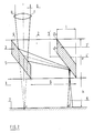
- FIG. 1 represents an openwork rotary member, constituted by a disc 1 in which are formed passage orifices 2, separated by solid parts or teeth 3. These orifices 2, of which only part is shown, are arranged in a neighboring crown from the edge of the disc 1; they may moreover, without prejudice to the invention, be constituted by slots cut in the periphery of the disc 1.
- the orifices 2 preferably have a regular section having two opposite sides oriented radially, to which correspond two opposite faces, called faces lateral radials, through holes.
- a passage orifice 2 is delimited by lateral faces 4, 5 ′ radial parallel to one another.
- These faces 4, 5 ′ are inclined at an angle ⁇ with respect to the direction of the axis 6 of the incident laser beam, which is perpendicular to the plane of the surface 7 of the cylinder to be treated.
- the axis of rotation of the disc 1 is parallel to the axis 6 of the laser beam.
- the laser beam is focused on the surface 7 by means of a lens 8.
- the parallel faces 4, 5 ′ ensure a double reflection of the laser beam and restore an outgoing beam whose axis 9 is parallel to the axis 6 of the incident beam.
- the beam impact area is moved from 0 to 0 ′, where preheating occurs.
- tooth 3 stops intercepting the axis beam 6 the impact zone returns to 0 in insufficient time for zone 0 ′ to have been able to arrive at 0.
- This delay is due to the enormous but inevitable difference speed between disk 1 and surface 7; this difference is such that the surface 7 can practically be considered as immobile between interruptions of the beam by two successive teeth such as 3 and 3 ′. Consequently, the preheating carried out at 0 ′ will only have an influence when the zone 0 ′ has reached 0, that is to say after a time such that the zone 0 ′ will have already cooled considerably. This time will also be longer as the aforementioned speed difference is greater.
- the face 4 is still inclined at an angle ⁇ relative to the axis 6 of the laser beam and it therefore deflects this beam towards the face 5 ′, exactly as in FIG. 2.
- the face 5 ′ is here inclined at an angle ⁇ relative to the axis 6 of the incident beam, and this angle ⁇ is such that the face 5 ′ returns the laser beam 9 towards the area of the surface 7 which the incident beam would reach if the tooth 3 did not exist.
- the 0 ′ beam impact area deflected 9 coincides with the direct beam impact zone 0 6. Still due to the speed difference between disc 1 and surface 7, zone 0 has practically not moved during the time required for the 'interruption of the beam 6 by the tooth 3.
- the deflected beam 9 therefore ensures effective preheating of the zone 0.
- the displacement of the zone 0 during this time is all the smaller the greater the aforementioned difference in speeds.
- the efficiency of preheating therefore increases with the speed difference between the disc 1 and the surface 7 of the cylinder to be treated.
- the present invention also relates to a rolling cylinder treated by means of the device which has just been described.
- a such a cylinder not only has an isotropic and homogeneous roughness, but also an increased lifetime, because the microcraters and their beads have been formed under optimal conditions. As a result, the wear of the rolls is greatly slowed down and the sheets rolled with such rolls have an extremely regular surface quality.
Landscapes
- Physics & Mathematics (AREA)
- Optics & Photonics (AREA)
- Engineering & Computer Science (AREA)
- Plasma & Fusion (AREA)
- Mechanical Engineering (AREA)
- Laser Beam Processing (AREA)
- Laser Surgery Devices (AREA)
- Mechanical Optical Scanning Systems (AREA)
- Semiconductor Lasers (AREA)
- Mechanical Light Control Or Optical Switches (AREA)
Priority Applications (1)
| Application Number | Priority Date | Filing Date | Title |
|---|---|---|---|
| AT88870145T ATE58319T1 (de) | 1987-09-11 | 1988-09-02 | Vorrichtung zur modulierung eines laserstrahls. |
Applications Claiming Priority (2)
| Application Number | Priority Date | Filing Date | Title |
|---|---|---|---|
| BE8701027A BE1000908A6 (fr) | 1987-09-11 | 1987-09-11 | Dispositif pour moduler un faisceau laser. |
| BE8701027 | 1987-09-11 |
Publications (2)
| Publication Number | Publication Date |
|---|---|
| EP0307384A1 true EP0307384A1 (de) | 1989-03-15 |
| EP0307384B1 EP0307384B1 (de) | 1990-11-14 |
Family
ID=3882853
Family Applications (1)
| Application Number | Title | Priority Date | Filing Date |
|---|---|---|---|
| EP88870145A Expired - Lifetime EP0307384B1 (de) | 1987-09-11 | 1988-09-02 | Vorrichtung zur Modulierung eines Laserstrahls |
Country Status (7)
| Country | Link |
|---|---|
| US (1) | US4885751A (de) |
| EP (1) | EP0307384B1 (de) |
| JP (1) | JPH01114816A (de) |
| AT (1) | ATE58319T1 (de) |
| BE (1) | BE1000908A6 (de) |
| DE (1) | DE3861083D1 (de) |
| ES (1) | ES2019706B3 (de) |
Families Citing this family (5)
| Publication number | Priority date | Publication date | Assignee | Title |
|---|---|---|---|---|
| US5886320A (en) * | 1996-09-03 | 1999-03-23 | International Business Machines Corporation | Laser ablation with transmission matching for promoting energy coupling to a film stack |
| US6002102A (en) * | 1997-02-25 | 1999-12-14 | Lsp Technologies, Inc. | Hidden surface laser shock processing |
| FI118301B (fi) * | 2005-05-25 | 2007-09-28 | St1 Biofuels Oy | Menetelmä etanoli-vesiseoksen valmistamiseksi |
| CN100491048C (zh) * | 2007-05-24 | 2009-05-27 | 上海交通大学 | 分光式激光毛化调制装置 |
| RU2654828C2 (ru) * | 2017-03-15 | 2018-05-22 | Общество с ограниченной ответственностью "МОЭМС-МОДУЛЬ" | Оптический модулятор (варианты) |
Citations (4)
| Publication number | Priority date | Publication date | Assignee | Title |
|---|---|---|---|---|
| US3942878A (en) * | 1974-08-05 | 1976-03-09 | Caterpillar Tractor Co. | Apparatus for modulating a high energy beam |
| DE3226811A1 (de) * | 1981-08-06 | 1983-03-24 | Centre de Recherches Métallurgiques-Centrum voor Research in de Metallurgie-Association sans but lucratif-Vereniging zonder winstoogmerk, Bruxelles | Verfahren zur modulation eines laserstrahlenbuendels |
| EP0119182A1 (de) * | 1983-03-11 | 1984-09-19 | CENTRE DE RECHERCHES METALLURGIQUES CENTRUM VOOR RESEARCH IN DE METALLURGIE Association sans but lucratif | Verfahren zur Verbesserung der Oberflächeneigenschaften von Walzen |
| US4519680A (en) * | 1982-11-05 | 1985-05-28 | Philip Morris Incorporated | Beam chopper for producing multiple beams |
Family Cites Families (5)
| Publication number | Priority date | Publication date | Assignee | Title |
|---|---|---|---|---|
| DE2840702A1 (de) * | 1977-09-22 | 1979-04-05 | Centre Rech Metallurgique | Verfahren und vorrichtung zur qualitaetsverbesserung von stahlfeinblechen |
| US4736095A (en) * | 1982-01-25 | 1988-04-05 | Symbol Technologies, Inc. | Narrow-bodied, single- and twin-windowed portable laser scanning head for reading bar code symbols |
| JPS61285780A (ja) * | 1985-06-12 | 1986-12-16 | Asahi Optical Co Ltd | レ−ザ発振装置 |
| US4703228A (en) * | 1985-08-28 | 1987-10-27 | Ga Technologies Inc. | Apparatus and method for providing a modulated electron beam |
| US4751706A (en) * | 1986-12-31 | 1988-06-14 | The United States Of America As Represented By The Secretary Of The Army | Laser for providing rapid sequence of different wavelengths |
-
1987
- 1987-09-11 BE BE8701027A patent/BE1000908A6/fr not_active IP Right Cessation
-
1988
- 1988-09-02 ES ES88870145T patent/ES2019706B3/es not_active Expired - Lifetime
- 1988-09-02 EP EP88870145A patent/EP0307384B1/de not_active Expired - Lifetime
- 1988-09-02 AT AT88870145T patent/ATE58319T1/de not_active IP Right Cessation
- 1988-09-02 DE DE8888870145T patent/DE3861083D1/de not_active Expired - Lifetime
- 1988-09-08 JP JP63225511A patent/JPH01114816A/ja active Granted
- 1988-09-12 US US07/242,974 patent/US4885751A/en not_active Expired - Fee Related
Patent Citations (4)
| Publication number | Priority date | Publication date | Assignee | Title |
|---|---|---|---|---|
| US3942878A (en) * | 1974-08-05 | 1976-03-09 | Caterpillar Tractor Co. | Apparatus for modulating a high energy beam |
| DE3226811A1 (de) * | 1981-08-06 | 1983-03-24 | Centre de Recherches Métallurgiques-Centrum voor Research in de Metallurgie-Association sans but lucratif-Vereniging zonder winstoogmerk, Bruxelles | Verfahren zur modulation eines laserstrahlenbuendels |
| US4519680A (en) * | 1982-11-05 | 1985-05-28 | Philip Morris Incorporated | Beam chopper for producing multiple beams |
| EP0119182A1 (de) * | 1983-03-11 | 1984-09-19 | CENTRE DE RECHERCHES METALLURGIQUES CENTRUM VOOR RESEARCH IN DE METALLURGIE Association sans but lucratif | Verfahren zur Verbesserung der Oberflächeneigenschaften von Walzen |
Also Published As
| Publication number | Publication date |
|---|---|
| BE1000908A6 (fr) | 1989-05-16 |
| ATE58319T1 (de) | 1990-11-15 |
| EP0307384B1 (de) | 1990-11-14 |
| ES2019706B3 (es) | 1991-07-01 |
| DE3861083D1 (de) | 1990-12-20 |
| JPH059766B2 (de) | 1993-02-05 |
| JPH01114816A (ja) | 1989-05-08 |
| US4885751A (en) | 1989-12-05 |
Similar Documents
| Publication | Publication Date | Title |
|---|---|---|
| EP0131487B1 (de) | Verfahren und Einrichtung zum Laserstrahlpunktschweissen | |
| EP2833054A2 (de) | Beleuchtungssystem mit perfektionierten Scanmitteln | |
| FR2789449A1 (fr) | Ventilateur a flux axial | |
| EP1551215A1 (de) | Verbesserter ausgerichteter schneiddraht für ein pflanzenschneidgerät | |
| FR2479994A1 (fr) | Dispositif de multiplexage de lumiere et appareil de combinaison de faisceaux comprenant un tel dispositif | |
| EP0307384B1 (de) | Vorrichtung zur Modulierung eines Laserstrahls | |
| FR2680841A1 (fr) | Joint a rainures transversales, a vitesse constante et ayant un centre fixe. | |
| EP0465282A1 (de) | Kugeldrehantrieb | |
| JPH01149010A (ja) | 回転ミラー走査装置 | |
| FR2781855A1 (fr) | Mecanisme de transmission de puissance utilisant des courroies metalliques | |
| FR3065536B1 (fr) | Miroir deformable a courbure variable et procede de fabrication d'un miroir associe | |
| JPH02303473A (ja) | 紙巻タバコに孔を作る方法及び装置 | |
| LU83535A1 (fr) | Procede pour moduler un faisceau laser | |
| FR2505564A1 (fr) | Dispositif de modification et d'uniformisation de l'intensite d'un faisceau laser de puissance | |
| EP0064444A1 (de) | Pyrotechnischer Leuchtsatz mit grosser Leuchtkraft | |
| US6738172B2 (en) | Rotating multi-faceted mirror for an optical scanning apparatus | |
| FR2610421A1 (fr) | Dispositif de deflexion de faisceau et imprimante a faisceau laser l'utilisant | |
| US5946124A (en) | Laser scanning unit having a noise reducing portion | |
| FR2768221A1 (fr) | Procede de fabrication d'un codeur optique pour palier a roulement et palier a roulement correspondant | |
| EP0161198A1 (de) | Drehbare, schraubenförmige Schwimmkörper für nautische oder andere Geräte | |
| FR2850239A1 (fr) | Tete de coupe pour debroussailleuse, coupe-bordures ou analogue | |
| FR2571195A1 (fr) | Procede et dispositif de restitution d'images par balayage suivant des lignes successives d'un support photosensible a l'aide d'un faisceau lumineux module | |
| EP1016890A1 (de) | Herstellungsverfahren von strahlfokussierende Flächen, besonders bei streifendem Einfallswinkel und Vorrichtung zur dessen Umsetzung | |
| FR2716462A1 (fr) | Procédé pour revêtir un substrat, et dispositif de revêtement pour la mise en Óoeuvre dudit procédé. | |
| EP1072816A1 (de) | Führungsglied, Gliederkette mit solch einem Glied und Motor mit solch einer Kette |
Legal Events
| Date | Code | Title | Description |
|---|---|---|---|
| PUAI | Public reference made under article 153(3) epc to a published international application that has entered the european phase |
Free format text: ORIGINAL CODE: 0009012 |
|
| AK | Designated contracting states |
Kind code of ref document: A1 Designated state(s): AT BE DE ES FR GB IT LU SE |
|
| 17P | Request for examination filed |
Effective date: 19890823 |
|
| 17Q | First examination report despatched |
Effective date: 19891025 |
|
| GRAA | (expected) grant |
Free format text: ORIGINAL CODE: 0009210 |
|
| AK | Designated contracting states |
Kind code of ref document: B1 Designated state(s): AT BE DE ES FR GB IT LU SE |
|
| REF | Corresponds to: |
Ref document number: 58319 Country of ref document: AT Date of ref document: 19901115 Kind code of ref document: T |
|
| REF | Corresponds to: |
Ref document number: 3861083 Country of ref document: DE Date of ref document: 19901220 |
|
| ITF | It: translation for a ep patent filed |
Owner name: INTERPATENT ST.TECN. BREV. |
|
| GBT | Gb: translation of ep patent filed (gb section 77(6)(a)/1977) | ||
| PLBE | No opposition filed within time limit |
Free format text: ORIGINAL CODE: 0009261 |
|
| STAA | Information on the status of an ep patent application or granted ep patent |
Free format text: STATUS: NO OPPOSITION FILED WITHIN TIME LIMIT |
|
| 26N | No opposition filed | ||
| PGFP | Annual fee paid to national office [announced via postgrant information from national office to epo] |
Ref country code: LU Payment date: 19930914 Year of fee payment: 6 |
|
| ITTA | It: last paid annual fee | ||
| EPTA | Lu: last paid annual fee | ||
| PG25 | Lapsed in a contracting state [announced via postgrant information from national office to epo] |
Ref country code: LU Free format text: LAPSE BECAUSE OF NON-PAYMENT OF DUE FEES Effective date: 19940902 |
|
| EAL | Se: european patent in force in sweden |
Ref document number: 88870145.5 |
|
| PGFP | Annual fee paid to national office [announced via postgrant information from national office to epo] |
Ref country code: GB Payment date: 19950829 Year of fee payment: 8 |
|
| PGFP | Annual fee paid to national office [announced via postgrant information from national office to epo] |
Ref country code: FR Payment date: 19950830 Year of fee payment: 8 |
|
| PGFP | Annual fee paid to national office [announced via postgrant information from national office to epo] |
Ref country code: SE Payment date: 19950831 Year of fee payment: 8 |
|
| PGFP | Annual fee paid to national office [announced via postgrant information from national office to epo] |
Ref country code: DE Payment date: 19950901 Year of fee payment: 8 Ref country code: BE Payment date: 19950901 Year of fee payment: 8 |
|
| PGFP | Annual fee paid to national office [announced via postgrant information from national office to epo] |
Ref country code: ES Payment date: 19950915 Year of fee payment: 8 |
|
| PGFP | Annual fee paid to national office [announced via postgrant information from national office to epo] |
Ref country code: AT Payment date: 19950925 Year of fee payment: 8 |
|
| PG25 | Lapsed in a contracting state [announced via postgrant information from national office to epo] |
Ref country code: GB Effective date: 19960902 Ref country code: AT Effective date: 19960902 |
|
| PG25 | Lapsed in a contracting state [announced via postgrant information from national office to epo] |
Ref country code: SE Effective date: 19960903 Ref country code: ES Free format text: LAPSE BECAUSE OF EXPIRATION OF PROTECTION Effective date: 19960903 |
|
| PG25 | Lapsed in a contracting state [announced via postgrant information from national office to epo] |
Ref country code: FR Effective date: 19960930 Ref country code: BE Effective date: 19960930 |
|
| BERE | Be: lapsed |
Owner name: CENTRE DE RECHERCHES METALLURGIQUES CENTRUM VOOR Effective date: 19960930 |
|
| GBPC | Gb: european patent ceased through non-payment of renewal fee |
Effective date: 19960902 |
|
| PG25 | Lapsed in a contracting state [announced via postgrant information from national office to epo] |
Ref country code: DE Effective date: 19970603 |
|
| EUG | Se: european patent has lapsed |
Ref document number: 88870145.5 |
|
| REG | Reference to a national code |
Ref country code: FR Ref legal event code: ST |
|
| REG | Reference to a national code |
Ref country code: FR Ref legal event code: ST |
|
| REG | Reference to a national code |
Ref country code: ES Ref legal event code: FD2A Effective date: 19990601 |
|
| PG25 | Lapsed in a contracting state [announced via postgrant information from national office to epo] |
Ref country code: IT Free format text: LAPSE BECAUSE OF NON-PAYMENT OF DUE FEES Effective date: 20050902 |