EP0307094A2 - Optical image rotators - Google Patents
Optical image rotators Download PDFInfo
- Publication number
- EP0307094A2 EP0307094A2 EP88307537A EP88307537A EP0307094A2 EP 0307094 A2 EP0307094 A2 EP 0307094A2 EP 88307537 A EP88307537 A EP 88307537A EP 88307537 A EP88307537 A EP 88307537A EP 0307094 A2 EP0307094 A2 EP 0307094A2
- Authority
- EP
- European Patent Office
- Prior art keywords
- rotator
- reflections
- layered
- light
- polarising
- Prior art date
- Legal status (The legal status is an assumption and is not a legal conclusion. Google has not performed a legal analysis and makes no representation as to the accuracy of the status listed.)
- Granted
Links
Images

Classifications
-
- G—PHYSICS
- G02—OPTICS
- G02B—OPTICAL ELEMENTS, SYSTEMS OR APPARATUS
- G02B27/00—Optical systems or apparatus not provided for by any of the groups G02B1/00 - G02B26/00, G02B30/00
- G02B27/28—Optical systems or apparatus not provided for by any of the groups G02B1/00 - G02B26/00, G02B30/00 for polarising
-
- G—PHYSICS
- G02—OPTICS
- G02B—OPTICAL ELEMENTS, SYSTEMS OR APPARATUS
- G02B17/00—Systems with reflecting surfaces, with or without refracting elements
- G02B17/02—Catoptric systems, e.g. image erecting and reversing system
-
- G—PHYSICS
- G02—OPTICS
- G02B—OPTICAL ELEMENTS, SYSTEMS OR APPARATUS
- G02B26/00—Optical devices or arrangements for the control of light using movable or deformable optical elements
- G02B26/08—Optical devices or arrangements for the control of light using movable or deformable optical elements for controlling the direction of light
-
- G—PHYSICS
- G02—OPTICS
- G02B—OPTICAL ELEMENTS, SYSTEMS OR APPARATUS
- G02B5/00—Optical elements other than lenses
- G02B5/30—Polarising elements
- G02B5/3083—Birefringent or phase retarding elements
Definitions
- rotators While many rotators are optically suitable for use with circularly polarised light, they generally have the disadvantage that they are asymmetric about their axis of rotation, and hence, when rotating at high speed, suffer from dynamic mechanical unbalance. Furthermore, it may be shown that, for good optical performance, the minimum circumscribed diameter of an Abbe or Vee-block rotator about its axis of rotation should be at least double the width of its optical entrance aperture, and such a large circumscribed diameter may be disadvantageous if a compact optical system is required.
- one or more reflective faces of an optical rotator has layered polarising means thereby to produce a predetermined polarisation effect of the rotator between input and output of a light beam.
- the present invention is also applicable to, and may be used with advantage in, optical systems which, prima facie, do not appear concerned with polarising optics.
- any optics system which uses a laser and requires a rotator will suffer from polarisation effects unless the present invention is used.
- the light entry and exit faces AB and DC respectively are each square in cross-section and perpendicular to the rotational axis XX′, and a circular entrance aperture (not shown) would have a diameter equal to or less than the length of the side AB.
- the paths of an axial light beam QQ′ and of a parallel non-axial light beam PP′ both undergo total internal reflection (TIR) at the surfaces FE, DG and HG.
- the upper and lower planar surfaces HD and BC are metallised with, for example, evaporated silver to provide two mirror reflections in the path of each of the light beams.
- the total number of reflections for each beam is five and, since this is an odd number, an image such as P′Q′ of a fixed object source PQ will rotate about the axis XX′ at double the rotational speed of the rotator.
- the geometry of the prisms is designed such that the light beams cross the air gap betwen the mating parallel faces FE and HG with normal incidence in the region I.
- the mating faces FE and GH are inclined at 45° to the axis XX′, while the metallised faces HD and BC are inclined at ⁇ 22.5° to the axis.
- the prisms are of an optical glass having, typically, a refractive index of the order of 1.76 for which the critical angle of incidence for total internal refraction is substantially 35°.
- Light is incident on the three faces FE, GH and DG at 45° and is totally internally reflected, with an angle of incidence of 45°, while light is incident on the two metallised faces HD and BC at 22.5° and is mirror
- multiple layer optically transmissive thin films are deposited on to one or more of the optically reflecting faces on a rotator in a controlled manner such that a total phase retardation of substantially 180° occurs between the p and s polarisation components of light transmitted through the rotator.
- the multiple layers may be deposited by such methods as evaporation or sputtering, and techniques for controlling their thickness are well-known.
- the films may be chosen from any known materials having refractive indices substantially as defined above. For wavelengths such as are generally used in optical recorders, in the order of 700 to 800 nm, the films may be all of a silicon oxide of general formula SiOx where x lies within the range 1 to 2. Each of the five films may be evaporated in turn from a SiO source, and the required refractive indices may be obtained by introducing varying amounts of oxygen into the evaporation chamber.
Landscapes
- Physics & Mathematics (AREA)
- General Physics & Mathematics (AREA)
- Optics & Photonics (AREA)
- Polarising Elements (AREA)
- Holo Graphy (AREA)
- Microscoopes, Condenser (AREA)
- Electrochromic Elements, Electrophoresis, Or Variable Reflection Or Absorption Elements (AREA)
- Preliminary Treatment Of Fibers (AREA)
- Optical Elements Other Than Lenses (AREA)
- Mechanical Light Control Or Optical Switches (AREA)
Abstract
Description
- The present invention is related to optical image rotators which are particularly, but not exclusively, suitable for use with multi-channel optical recording systems.
- Multi-channel optical tape recording systems utilising polarising reading optics are disclosed in our published European Patent Application No. 0263656 and British Patent Application No. 8720924. In such systems, an optical image rotator is disposed in the path of circularly polarised incident and reflected light beams. A preferred embodiment of rotator disclosed in the aforementioned European Patent Application is a modified form of Vee-block or Abbe rotator having only three metallised reflecting surfaces, and no totally internally reflecting surfaces, in order that the reflections within the rotator have a relatively small polarising effect on light passing through the rotator. While many rotators are optically suitable for use with circularly polarised light, they generally have the disadvantage that they are asymmetric about their axis of rotation, and hence, when rotating at high speed, suffer from dynamic mechanical unbalance. Furthermore, it may be shown that, for good optical performance, the minimum circumscribed diameter of an Abbe or Vee-block rotator about its axis of rotation should be at least double the width of its optical entrance aperture, and such a large circumscribed diameter may be disadvantageous if a compact optical system is required.
- In contrast, a Pechan rotator is symmetrical about its axis of rotation and may operate satisfactorily with a considerably lower minimum circumscribed diameter relative to its optical entrance aperture. A Pechan rotator is therefore mechanically preferable to a Vee-block or an Abbe rotator. A conventional Pechan rotator, however has five reflecting surfaces in the optical path, three of which are totally internally reflecting (TIR), and the greater number of reflections would introduce undesirable polarisation effects to an incident circularly polarised light beam, giving rise to an unwanted cyclic amplitude modulation if used in an optical recording system which includes polarising replay optics.
- It is an object of the present invention to provide an improved optical image rotator particularly suited for use with polarising optical systems.
- In accordance with the present invention, one or more reflective faces of an optical rotator has layered polarising means thereby to produce a predetermined polarisation effect of the rotator between input and output of a light beam.
- Preferably, the polarising means comprises a plurality of layers of optically transmissive thin films, for example of silicon oxide or magnesium fluoride.
- The predetermined polarisation effect may be to provide a total phase retardation of 180° between the p and s polarisation components between a light beam input to the rotator and that beam upon output therefrom; other predetermined polarisation effects may be to provide a retardation of 0°, 90° or 270°.
- Clearly, the present invention is also applicable to, and may be used with advantage in, optical systems which, prima facie, do not appear concerned with polarising optics. Thus for example, as a laser produces inherently polarised light, any optics system which uses a laser and requires a rotator will suffer from polarisation effects unless the present invention is used.
- The invention will now be described, by way of example, with reference to the accompanying drawings in which
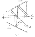
- Figure 1 is a side view of a Pechan optical rotator.
- Figure 2 is a graphical representation of a reflectivity and phase retardation properties of a Pechan optical rotator according to the invention.
- Referring to Figure 1, a Pechan rotator rotates symmetrically about the axis XX′, and would normally be fixed in or to a motor-driven hollow shaft (not shown) as described in our above mentioned Patent Applications. The light path rotator has the geometry of a conventional Pechan rotator as is disclosed, for example, in the published paper "Image Rotation Devices - A Comparative Survey" by D.W. Swift, Optics and Laser Technology, August 1972, pages 175 to 188. The rotator comprises two prisms ABCEF and HGD firmly fixed to one another with a small air gap between the adjoining diagonal planar faces FE and HG. The light entry and exit faces AB and DC respectively are each square in cross-section and perpendicular to the rotational axis XX′, and a circular entrance aperture (not shown) would have a diameter equal to or less than the length of the side AB. The paths of an axial light beam QQ′ and of a parallel non-axial light beam PP′ both undergo total internal reflection (TIR) at the surfaces FE, DG and HG. The upper and lower planar surfaces HD and BC are metallised with, for example, evaporated silver to provide two mirror reflections in the path of each of the light beams. The total number of reflections for each beam is five and, since this is an odd number, an image such as P′Q′ of a fixed object source PQ will rotate about the axis XX′ at double the rotational speed of the rotator. The geometry of the prisms is designed such that the light beams cross the air gap betwen the mating parallel faces FE and HG with normal incidence in the region I. The mating faces FE and GH are inclined at 45° to the axis XX′, while the metallised faces HD and BC are inclined at ± 22.5° to the axis. The prisms are of an optical glass having, typically, a refractive index of the order of 1.76 for which the critical angle of incidence for total internal refraction is substantially 35°. Light is incident on the three faces FE, GH and DG at 45° and is totally internally reflected, with an angle of incidence of 45°, while light is incident on the two metallised faces HD and BC at 22.5° and is mirror reflected.
- It is well known that the total internal reflection of light is normally accompanied by marked polarisation changes and phase retardations which would disturb the state of polarisation of an incident light beam, and that a metallized mirror reflection may exhibit a similar effect, but to a lesser extent. The total polarising effect of the five reflections is likely to be unacceptably high in a conventional Pechan rotator when required to operate with polarised light.
- In this embodiment of the present invention, multiple layer optically transmissive thin films are deposited on to one or more of the optically reflecting faces on a rotator in a controlled manner such that a total phase retardation of substantially 180° occurs between the p and s polarisation components of light transmitted through the rotator.
- A retardation of 180° rather than one of 0° retardation is chosen in order that the rotator may behave optically as a half-wave plate. A half-wave plate is known, when rotated, to rotate the plan or rotation of incident polarised light and, if an optical rotator has a total phase retardation of 180°, any polarisation of the incident light will rotate with the image rather than remain stationary, as would be the case with zero retardation.
- The light path crossing the diagonally inclined faces FE and HG in the region I has normal incidence, and it is desirable that these surfaces should both be provided with coatings which are anti-reflective at normal incidence, while maintaining the constraint that the total phase retardation encountered in all five reflections is substantially 180°.
- In a Pechan prism, the inherent polarisation effects in the prism may be corrected by applying three substantially identical multi-layer coatings to each of the totally internally reflecting surfaces, FE, GH and DE and no coatings to the two metallised surfaces. The desired correction of polarisation effects introduced by the five reflective surfaces associated with an overall 180° phase retardation and anti-reflective properties at normal incidence for each of the surfaces FE and HG may be achieved by applying to each of the three glass surfaces FE, HG and DG a multi-layer coating with layer properties substantially as follows:-

- If different coatings are used then it is possible to obtain flat angle responses from each surface thus allowing for angular misalignments in the system. Furthermore, the greater number of variables can allow a more desirable coating to be designed.
- The Figure 2 shows overall typical examples of reflectivity and phase retardation for a Pechan prism having such coatings, plotted against the angle of incidence of an incoming light beam to the entry face AB. It is seen that, at normal incidence, the phase retardation is substantially 180° and that the overall reflectivity is very low.
- It will be appreciated that the invention strictly applies to monochromatic light of wavelength λ, and if the wavelength is changed, the film thickness should, in theory, change proportionally. In practice, however, variations of up to the order of 10% in for fixed film thicknesses are generally tolerable without causing unacceptable departures from the ideal reflectivity and phase response. As such, a Pechan rotator for use in a dual wavelength multi-beam optical recording system with polarising read optics could be satisfactory provided that the write and read beam wavelengths do not differ by more than the order of 10%.
- The multiple layers may be deposited by such methods as evaporation or sputtering, and techniques for controlling their thickness are well-known. The films may be chosen from any known materials having refractive indices substantially as defined above. For wavelengths such as are generally used in optical recorders, in the order of 700 to 800 nm, the films may be all of a silicon oxide of general formula SiOx where x lies within the
range 1 to 2. Each of the five films may be evaporated in turn from a SiO source, and the required refractive indices may be obtained by introducing varying amounts of oxygen into the evaporation chamber. - It will be apparent to those skilled in the art that the above embodiment of the invention is not a unique solution, and other variants of film thickness, layer number, and refractive index may be suitably optimised to give an overall half-wave phase retardation. Alternative solutions may be derived theoretically or optimised experimentally by those suitably skilled in the art. The coatings, for example, need not necessarily be identical on each of the totally internally reflecting surfaces, and in other embodiments, on or both metallised surfaces or the entry and exit surfaces may be provided with suitably optimised coatings.
- By appropriate selection of layer materials and thickness, other values of retardation can be duly achieved.
- Furthermore, the invention is not limited to Pechan rotators. Alternative optical rotators, such as Dove, Schmitt, Vee-block or Abbe types, may be modified in similar fashion i.e. by the application of suitably optimised multi-layer films to one or more reflecting surfaces in order to provide overall 180° phase retardation, preferably associated with suitable anti-reflective properties.
- It will be further apparent to those skilled in the art that the use of the invention is not limited to optical recording devices. The invention may be suitably used in any optical system where it is required to rotate an image of a fixed object source about an axis and in which it is advantageous for any state of polarisation present in the incident light beam to be rotated with the image.
- The terms "optical" and "light" as used herein are not intended to be limited to visible radiation but instead are intended to embrace other forms of electromagnetic radiation, such as infra-red radiation for example, which can be handled, insofar as the invention is concerned, in the same way as visible radiation.
Claims (11)

Priority Applications (1)
| Application Number | Priority Date | Filing Date | Title |
|---|---|---|---|
| AT88307537T ATE87373T1 (en) | 1987-09-05 | 1988-08-15 | OPTICAL IMAGE INVERSION SYSTEMS. |
Applications Claiming Priority (2)
| Application Number | Priority Date | Filing Date | Title |
|---|---|---|---|
| GB878720923A GB8720923D0 (en) | 1987-09-05 | 1987-09-05 | Optical image rotators |
| GB8720923 | 1987-09-05 |
Publications (3)
| Publication Number | Publication Date |
|---|---|
| EP0307094A2 true EP0307094A2 (en) | 1989-03-15 |
| EP0307094A3 EP0307094A3 (en) | 1989-04-19 |
| EP0307094B1 EP0307094B1 (en) | 1993-03-24 |
Family
ID=10623345
Family Applications (1)
| Application Number | Title | Priority Date | Filing Date |
|---|---|---|---|
| EP88307537A Expired - Lifetime EP0307094B1 (en) | 1987-09-05 | 1988-08-15 | Optical image rotators |
Country Status (7)
| Country | Link |
|---|---|
| US (1) | US4948228A (en) |
| EP (1) | EP0307094B1 (en) |
| JP (1) | JPH01152401A (en) |
| AT (1) | ATE87373T1 (en) |
| CA (1) | CA1302138C (en) |
| DE (1) | DE3879593T2 (en) |
| GB (1) | GB8720923D0 (en) |
Cited By (3)
| Publication number | Priority date | Publication date | Assignee | Title |
|---|---|---|---|---|
| WO1990015354A1 (en) * | 1989-06-02 | 1990-12-13 | Optische Werke G. Rodenstock | Device for deflecting a ray beam |
| WO1991019377A1 (en) * | 1990-06-05 | 1991-12-12 | Gec Ferranti Defence Systems Limited | Improvements in thermal imagers |
| EP2062018A4 (en) * | 2006-10-31 | 2009-10-21 | J A Woollam Co Inc | Deviation angle self compensating substantially achromatic retarder |
Families Citing this family (20)
| Publication number | Priority date | Publication date | Assignee | Title |
|---|---|---|---|---|
| US5166820A (en) * | 1990-03-13 | 1992-11-24 | Citizen Watch Co., Ltd. | Light beam scanning apparatus |
| US5214528A (en) * | 1990-09-14 | 1993-05-25 | Konica Corporation | Optical beam scanning apparatus |
| US5132822A (en) * | 1990-11-29 | 1992-07-21 | Gte Laboratories Incorporated | Optical switch |
| US5191485A (en) * | 1991-09-19 | 1993-03-02 | Infographix, Inc. | Prism for image rotation |
| US5374876A (en) * | 1991-12-19 | 1994-12-20 | Hiroshi Horibata | Portable multi-color signal light with selectively switchable LED and incandescent illumination |
| JPH06222212A (en) * | 1992-12-03 | 1994-08-12 | Matsushita Electric Ind Co Ltd | Polarization surface rotating optical device, polarization transformation optical device, and projection type display device |
| US5552922A (en) * | 1993-04-12 | 1996-09-03 | Corning Incorporated | Optical system for projection display |
| US6072625A (en) * | 1997-02-03 | 2000-06-06 | Olympus Optical Co., Ltd. | Optical microscope apparatus |
| EP1051582B1 (en) * | 1998-02-05 | 2003-08-20 | Zumtobel Staff GmbH | Lighting fixture |
| US6282026B1 (en) | 1998-02-05 | 2001-08-28 | 3M Innovative Properties Company | Retroreflectors having two optical surfaces and varying retroreflectivity |
| US6045230A (en) * | 1998-02-05 | 2000-04-04 | 3M Innovative Properties Company | Modulating retroreflective article |
| US6039478A (en) * | 1999-04-16 | 2000-03-21 | Shin Jiuh Corp. | Ergonomical keyboard assembly |
| GB0110492D0 (en) * | 2001-04-28 | 2001-06-20 | Secr Defence | Optical device |
| EP1478965A1 (en) * | 2002-02-28 | 2004-11-24 | 3M Innovative Properties Company | Compound polarization beam splitters |
| US20040021940A1 (en) * | 2002-07-30 | 2004-02-05 | Gunther John E. | Optical polarization rotating device |
| JP2004226811A (en) * | 2003-01-24 | 2004-08-12 | Institute Of Physical & Chemical Research | Micro optical element and manufacturing method thereof |
| KR100901146B1 (en) | 2007-06-14 | 2009-06-04 | 한국광기술원 | Image Rotator Using Right Angle Mirror Unit and Its Method |
| JP6539886B2 (en) * | 2014-10-01 | 2019-07-10 | 鎌倉光機株式会社 | Image reversing prism |
| CN110927974B (en) * | 2019-12-18 | 2022-05-10 | 业成科技(成都)有限公司 | Optical imaging module and VR electronic equipment |
| CN110955052A (en) * | 2019-12-18 | 2020-04-03 | 业成科技(成都)有限公司 | Optical imaging module and VR electronic equipment |
Family Cites Families (15)
| Publication number | Priority date | Publication date | Assignee | Title |
|---|---|---|---|---|
| US2147615A (en) * | 1936-06-18 | 1939-02-14 | Baroni Augusto | Optical device for panoramic telescopes and the like, equivalent to the amici rotating prism |
| JPS5740481B2 (en) * | 1972-10-04 | 1982-08-27 | ||
| US4209224A (en) * | 1977-12-12 | 1980-06-24 | Ford Aerospace & Communications Corp. | Prismatic beam rotator for an optical beam projector |
| US4355870A (en) * | 1980-12-24 | 1982-10-26 | Lovelace Alan M Administrator | Rhomboid prism pair for rotating the plane of parallel light beams |
| JPS57132114A (en) * | 1981-02-07 | 1982-08-16 | Olympus Optical Co Ltd | Dividing method of light flux |
| JPS57161811A (en) * | 1981-03-31 | 1982-10-05 | Tech Res & Dev Inst Of Japan Def Agency | Optical device |
| DE3137442A1 (en) * | 1981-09-21 | 1983-03-31 | Siemens AG, 1000 Berlin und 8000 München | OPTICAL POLARIZER |
| DE3206040A1 (en) * | 1982-02-19 | 1983-09-01 | Siemens AG, 1000 Berlin und 8000 München | REFLECTION-FREE OPTICAL POLARIZER WITH A PRISMA |
| EP0100178B1 (en) * | 1982-07-14 | 1988-09-28 | Fujitsu Limited | Polarizing elements |
| US4514047A (en) * | 1982-10-12 | 1985-04-30 | Magnetic Peripherals Inc. | On-axis achromatic quarterwave retarder prism |
| US4525034A (en) * | 1982-12-07 | 1985-06-25 | Simmons Clarke V | Polarizing retroreflecting prism |
| US4595261A (en) * | 1983-10-13 | 1986-06-17 | International Business Machines Corporation | Phase retardation element and prism for use in an optical data storage system |
| US4657356A (en) * | 1984-07-04 | 1987-04-14 | Canon Kabushiki Kaisha | Stereoscopic microscope with a pair of image rotation correcting means |
| JPS62112234A (en) * | 1985-11-11 | 1987-05-23 | Hitachi Ltd | Rotating optical system |
| EP0263656A3 (en) * | 1986-10-06 | 1989-11-15 | Thorn Emi Plc | Tape recording |
-
1987
- 1987-09-05 GB GB878720923A patent/GB8720923D0/en active Pending
-
1988
- 1988-08-15 EP EP88307537A patent/EP0307094B1/en not_active Expired - Lifetime
- 1988-08-15 DE DE8888307537T patent/DE3879593T2/en not_active Expired - Fee Related
- 1988-08-15 AT AT88307537T patent/ATE87373T1/en active
- 1988-09-02 US US07/239,993 patent/US4948228A/en not_active Expired - Fee Related
- 1988-09-02 CA CA000576472A patent/CA1302138C/en not_active Expired - Lifetime
- 1988-09-05 JP JP63220580A patent/JPH01152401A/en active Pending
Cited By (3)
| Publication number | Priority date | Publication date | Assignee | Title |
|---|---|---|---|---|
| WO1990015354A1 (en) * | 1989-06-02 | 1990-12-13 | Optische Werke G. Rodenstock | Device for deflecting a ray beam |
| WO1991019377A1 (en) * | 1990-06-05 | 1991-12-12 | Gec Ferranti Defence Systems Limited | Improvements in thermal imagers |
| EP2062018A4 (en) * | 2006-10-31 | 2009-10-21 | J A Woollam Co Inc | Deviation angle self compensating substantially achromatic retarder |
Also Published As
| Publication number | Publication date |
|---|---|
| US4948228A (en) | 1990-08-14 |
| GB8720923D0 (en) | 1987-10-14 |
| DE3879593D1 (en) | 1993-04-29 |
| CA1302138C (en) | 1992-06-02 |
| JPH01152401A (en) | 1989-06-14 |
| DE3879593T2 (en) | 1993-09-23 |
| EP0307094B1 (en) | 1993-03-24 |
| ATE87373T1 (en) | 1993-04-15 |
| EP0307094A3 (en) | 1989-04-19 |
Similar Documents
| Publication | Publication Date | Title |
|---|---|---|
| US4948228A (en) | Optical image rotators | |
| US4084883A (en) | Reflective polarization retarder and laser apparatus utilizing same | |
| US5912762A (en) | Thin film polarizing device | |
| US4991937A (en) | Birefringence diffraction grating type polarizer | |
| US4221464A (en) | Hybrid Brewster's angle wire grid infrared polarizer | |
| US4966438A (en) | Dielectric layer polarizer | |
| US4536063A (en) | Transmissive phase retarder | |
| US6487014B2 (en) | High isolation optical switch, isolator or circulator having thin film polarizing beam-splitters | |
| US5460888A (en) | Multi-layered optical film | |
| US5339441A (en) | Polarizing device with optically contacted thin film interface for high power density ultraviolet light | |
| US7012747B2 (en) | Polarizing beam splitter and polarizer using the same | |
| US4609258A (en) | Diode laser collimator | |
| US4966437A (en) | Fault-tolerant anti-reflective coatings | |
| US5822124A (en) | Beam splitter | |
| JP2790669B2 (en) | Polarizer | |
| US3563633A (en) | Phase-compensated trihedral reflectors for interferometer systems | |
| CA2137972C (en) | Beam splitter and optical coupler using the same | |
| US4595261A (en) | Phase retardation element and prism for use in an optical data storage system | |
| JP2000137109A (en) | Reflection preventive device using diffraction grating | |
| US5319494A (en) | Light waveguide type polarized light beam splitter | |
| EP0845111B1 (en) | Thin film polarizing device | |
| CN113534300B (en) | Anti-PT symmetrical photon multilayer capable of realizing reflectivity directional regulation and control | |
| US6229645B1 (en) | Polarization selecting optical element using a porro prism incorporating a thin film polarizer in a single element | |
| CN1182217A (en) | Multiple-film polarizing beam splitter utilizing birefraction film | |
| JPH08146218A (en) | Polarizing beam splitter |
Legal Events
| Date | Code | Title | Description |
|---|---|---|---|
| PUAI | Public reference made under article 153(3) epc to a published international application that has entered the european phase |
Free format text: ORIGINAL CODE: 0009012 |
|
| PUAL | Search report despatched |
Free format text: ORIGINAL CODE: 0009013 |
|
| AK | Designated contracting states |
Kind code of ref document: A2 Designated state(s): AT BE CH DE ES FR GB GR IT LI LU NL SE |
|
| AK | Designated contracting states |
Kind code of ref document: A3 Designated state(s): AT BE CH DE ES FR GB GR IT LI LU NL SE |
|
| 17P | Request for examination filed |
Effective date: 19890810 |
|
| 17Q | First examination report despatched |
Effective date: 19920212 |
|
| GRAA | (expected) grant |
Free format text: ORIGINAL CODE: 0009210 |
|
| AK | Designated contracting states |
Kind code of ref document: B1 Designated state(s): AT BE CH DE ES FR GB GR IT LI LU NL SE |
|
| PG25 | Lapsed in a contracting state [announced via postgrant information from national office to epo] |
Ref country code: LI Effective date: 19930324 Ref country code: ES Free format text: THE PATENT HAS BEEN ANNULLED BY A DECISION OF A NATIONAL AUTHORITY Effective date: 19930324 Ref country code: IT Free format text: LAPSE BECAUSE OF FAILURE TO SUBMIT A TRANSLATION OF THE DESCRIPTION OR TO PAY THE FEE WITHIN THE PRESCRIBED TIME-LIMIT;WARNING: LAPSES OF ITALIAN PATENTS WITH EFFECTIVE DATE BEFORE 2007 MAY HAVE OCCURRED AT ANY TIME BEFORE 2007. THE CORRECT EFFECTIVE DATE MAY BE DIFFERENT FROM THE ONE RECORDED. Effective date: 19930324 Ref country code: BE Effective date: 19930324 Ref country code: SE Effective date: 19930324 Ref country code: AT Effective date: 19930324 Ref country code: CH Effective date: 19930324 Ref country code: GR Free format text: LAPSE BECAUSE OF FAILURE TO SUBMIT A TRANSLATION OF THE DESCRIPTION OR TO PAY THE FEE WITHIN THE PRESCRIBED TIME-LIMIT Effective date: 19930324 |
|
| REF | Corresponds to: |
Ref document number: 87373 Country of ref document: AT Date of ref document: 19930415 Kind code of ref document: T |
|
| REF | Corresponds to: |
Ref document number: 3879593 Country of ref document: DE Date of ref document: 19930429 |
|
| ET | Fr: translation filed | ||
| REG | Reference to a national code |
Ref country code: CH Ref legal event code: PL |
|
| PG25 | Lapsed in a contracting state [announced via postgrant information from national office to epo] |
Ref country code: LU Free format text: LAPSE BECAUSE OF NON-PAYMENT OF DUE FEES Effective date: 19930831 |
|
| PGFP | Annual fee paid to national office [announced via postgrant information from national office to epo] |
Ref country code: NL Payment date: 19930831 Year of fee payment: 6 |
|
| PLBE | No opposition filed within time limit |
Free format text: ORIGINAL CODE: 0009261 |
|
| STAA | Information on the status of an ep patent application or granted ep patent |
Free format text: STATUS: NO OPPOSITION FILED WITHIN TIME LIMIT |
|
| 26N | No opposition filed | ||
| PGFP | Annual fee paid to national office [announced via postgrant information from national office to epo] |
Ref country code: FR Payment date: 19940831 Year of fee payment: 7 |
|
| PGFP | Annual fee paid to national office [announced via postgrant information from national office to epo] |
Ref country code: DE Payment date: 19941027 Year of fee payment: 7 |
|
| PG25 | Lapsed in a contracting state [announced via postgrant information from national office to epo] |
Ref country code: NL Effective date: 19950301 |
|
| NLV4 | Nl: lapsed or anulled due to non-payment of the annual fee | ||
| PG25 | Lapsed in a contracting state [announced via postgrant information from national office to epo] |
Ref country code: FR Effective date: 19960430 |
|
| PG25 | Lapsed in a contracting state [announced via postgrant information from national office to epo] |
Ref country code: DE Effective date: 19960501 |
|
| REG | Reference to a national code |
Ref country code: GB Ref legal event code: 732E |
|
| REG | Reference to a national code |
Ref country code: FR Ref legal event code: ST |
|
| REG | Reference to a national code |
Ref country code: GB Ref legal event code: 746 Effective date: 19960523 |
|
| PGFP | Annual fee paid to national office [announced via postgrant information from national office to epo] |
Ref country code: GB Payment date: 19960717 Year of fee payment: 9 |
|
| PG25 | Lapsed in a contracting state [announced via postgrant information from national office to epo] |
Ref country code: GB Free format text: LAPSE BECAUSE OF NON-PAYMENT OF DUE FEES Effective date: 19970815 |
|
| GBPC | Gb: european patent ceased through non-payment of renewal fee |
Effective date: 19970815 |