EP0306608B1 - Drawing machine - Google Patents
Drawing machine Download PDFInfo
- Publication number
- EP0306608B1 EP0306608B1 EP88106243A EP88106243A EP0306608B1 EP 0306608 B1 EP0306608 B1 EP 0306608B1 EP 88106243 A EP88106243 A EP 88106243A EP 88106243 A EP88106243 A EP 88106243A EP 0306608 B1 EP0306608 B1 EP 0306608B1
- Authority
- EP
- European Patent Office
- Prior art keywords
- lever
- slide
- tongue
- clamping jaws
- clamping
- Prior art date
- Legal status (The legal status is an assumption and is not a legal conclusion. Google has not performed a legal analysis and makes no representation as to the accuracy of the status listed.)
- Expired - Lifetime
Links
Images


Classifications
-
- B—PERFORMING OPERATIONS; TRANSPORTING
- B21—MECHANICAL METAL-WORKING WITHOUT ESSENTIALLY REMOVING MATERIAL; PUNCHING METAL
- B21C—MANUFACTURE OF METAL SHEETS, WIRE, RODS, TUBES OR PROFILES, OTHERWISE THAN BY ROLLING; AUXILIARY OPERATIONS USED IN CONNECTION WITH METAL-WORKING WITHOUT ESSENTIALLY REMOVING MATERIAL
- B21C1/00—Manufacture of metal sheets, metal wire, metal rods, metal tubes by drawing
- B21C1/16—Metal drawing by machines or apparatus in which the drawing action is effected by other means than drums, e.g. by a longitudinally-moved carriage pulling or pushing the work or stock for making metal sheets, bars, or tubes
- B21C1/27—Carriages; Drives
- B21C1/28—Carriages; Connections of grippers thereto; Grippers
Definitions
- the invention relates to a drawing machine according to the preamble of claim 1. It relates in particular to the control of the clamping jaws in the carriage.
- the invention is primarily used in continuously operating drawing machines which work with two drawing carriages which pull wire through a drawing nozzle without interruption and in alternation.
- the invention particularly relates to the control of wedge-shaped clamping jaws on drawing machines, which are usually mounted in a wedge-shaped cut-out in the drawing carriage, which, once clamped with the workpiece under tension, no longer require any external clamping force and which automatically operate when the Open traction.
- other clamping devices can also be controlled with the solution according to the invention.
- Both tensioning carriages have a short distance with overlapping pulling task in order to ensure a continuous pulling of the wire. This distance of overlap is made as short as possible, since it shortens the effective drawing length of each drawing carriage. The shorter the overlap distance, the more precise the tension and the loosening of the wire must be.
- the cam is designed and aligned so that in the dead center position of the slide, just before the start of drawing, the lever almost moves up to the cam and that when the slide starts to work, the cam the lever receding due to its shape, still in the overlap phase, catches up and actuated so that the clamping jaws are pressed against the workpiece. Under curve you can provide any kind of obstacle or control element that actuates the lever on the slide.
- the invention is therefore based on the object of finding a control of the clamping jaws on the drawing slide which works precisely with a minimum of effort and is independent of the drawing speed.
- the control and function of the clamping jaws should be easily manageable.
- the pull slide does not require any supply lines that connect the moving slide to the machine body.
- the evasive movement takes place against the force of a spring, which allows this evasive movement and initiates the snapping back of the lever and curve into the same plane as soon as the guardrail clears the way.
- the lever Shortly before the pressure point position of the slide is reached, the lever has passed the guide surface and the lever and the curve jump into the same plane with the help of the spring action.
- the term spring is to be understood that every energy store or energy source can be meant by this.
- the advantage of this embodiment is that even if a roller is used to drive the curve, control of the lever can begin immediately after the curve has jumped into the working plane of the lever. An empty path for bringing the lever / roller and curve into contact is eliminated.
- the overload spring in the kinematic chain between the machine body and the clamping jaws is preferably designed as a torsion bar, which is arranged in a bridge across the drawing slide.
- a further embodiment of the invention is shown in claim 6. Basically, this unlocking would be unnecessary in the wedge-shaped jaws described at the beginning, since these automatically open when the pulling force ceases. Due to wear or contamination of the wedge-shaped However, this automatism can be disturbed by drawing jaws.
- the unlocking device is used in this case for the emergency release of the clamping jaws. With other types of clamping devices, unlocking may also be necessary for normal operation of the clamping jaws.
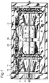
- FIG. 1 shows a Conti drawing machine 1 with a machine body 2, a drawing nozzle 3 and two tensioning carriages 5, 25, which are movable in slide paths 4, 40 in the machine body 2 in the drawing direction 15 and are moved back and forth in an alternating sequence by a drive 9 will.
- the drive takes place via a rotating shaft 23 mounted in the machine body parallel to the direction of drawing.
- On this shaft sleeves are fastened in a known manner, which bear curves 24, 25, approximately elliptically around their circumference, on which the slides 5, 35 are guided with rollers (not shown).
- the movements of the drawing slides 5, 35 are usually in opposite directions during operation of the drawing machine. When the carriage 5 pulls, the carriage 35 runs back and vice versa. In order to ensure a continuous extraction of the wire-shaped workpiece 8, both drawing slides have to work together in the drawing direction 15 for as short a time as possible of a few milliseconds. During this time, the train is handed over by one tension wagon and taken over by the other tension wagon.
- FIG. 1 Such a situation is shown in Fig. 1.
- the tensioning carriage 35 is at the end of its working distance and the tensioning carriage 5 is at the beginning of its working distance. So that the clamping carriage 5 can take over the pull-out force, its clamping jaws 6, 7 must be closed.
- the clamping jaws 6, 7 are closed with the aid of the curve 11 on the tongue 16 and the clamping lever 10 with the roller 22 guided above it.
- the clamping of the workpiece 8 is basically released automatically when the clamping carriage 5 takes over the pull-out force and the wire length between the two clamping carriages becomes stress-free.
- an unlocking device 21 is provided with which the clamping jaws 26, 27 of the clamping carriage 35 are forcibly released if the automatic release of the Jaws should not have worked.
- a bridge extends across each tensioning carriage and is fastened to it in bearing blocks 28, 30. This bridge extends with the control levers 10 and 20 for the clamping jaws 6, 7 and 26, 27 to in the area of the machine body or the slide tracks 4, 40.
- the tensioning carriage 25 has the same structure.
- a rotatable clamping tube 39 is guided through the bearing blocks 28, 30, from each of which a clamping lever 38 projects downward in the region of the clamping jaws 6, 7 and engages in recesses 41 in the clamping jaws 6, 7.
- Rotation of the clamping tube 39 causes the clamping jaws to move in or against the direction of drawing. Due to the wedge-shaped design of the clamping jaws, the clamping jaws are also moved radially towards the wire 8.
- the clamping of the wire 8 achieved in this way is self-locking as soon as the drawing slide exerts tension on the wire.
- the pressing force which is exerted by the tensioning levers 38 is unnecessary during the train.
- the pivoting of the tensioning tube 38 and the tensioning lever 28 arranged thereon in a rotationally fixed manner takes place with the aid of the control lever 10 and the roller 22 mounted on its free end.
- the working or pivoting plane of the lever 10 is designated by 17.
- the lever 10 with the roller 22 is controlled by a curve 11.
- the curve 11 is formed on the tongue 16.
- the clamping jaws 6, 7 are closed.
- the tongue 16 on which the curve 11 is formed is attached to the machine body 2 with a joint 37. It is located directly next to the drawing carriage 5 within the reach of the roller 22. It extends only over the last part of the drawing section of the drawing carriage 5.
- the lever 10 When the curve 11 travels through the roller 22, the lever 10, the tensioning tube 39 and the tensioning lever 38 are pivoted .
- the clamping jaws 6, 7 thus shifted against the direction of drawing 15 thereby clamp the wire 8.
- the drawing carriage 5 pulls the wire 8 through the drawing nozzle 3 by about 1 meter and transfers it to the drawing carriage 35. After the clamping jaws 6, 7 have detached from the wire 8, the clamping carriage 5 moves back.
- the roller 22 On the way back, the roller 22 does not travel over the curve 11, but pushes the tongue 16 aside against the force of the spring 14 attached to the machine body 2 and thereby slides along the guide surface 12 on the side of the tongue 16 like on a guardrail.
- the tongue 16 is pivoted in the joint 37 (Fig. 3). As soon as the roller 22 has passed the mountain formed by the curve 11, the tongue 16 snaps back from the side under the action of the spring 14 and the bottom of the valley in front of the mountain of the curve 11 comes to rest under the roller 22 on the lever 10. The curve 16 is thus again in the working plane 17 of the lever 10 which is slightly offset by the roller.
- the pivoting of the tongue 16 is limited by the stop 18 on the machine body 2.
- An essential advantage of the invention is that this snap-back of the tongue 16 with the curve 11 is so precise and punctual that the accuracy of this point in time cannot be surpassed by any electronic, hydraulic or pneumatic control.
- the control of the jaws can begin immediately after the tongue snaps back, practically simultaneously with the start of the working stroke. Basically, there is no dead end at the beginning of the work stroke.
- a spring is provided in the kinematic chain up to the clamping jaws 6, 7.
- the spring is designed as a torsion bar 19.
- the lever 10 itself is non-rotatably connected to the torsion bar 19 at one end.
- the torsion bar extends over the entire width of the drawing slide 5 within the tension tube 39. At its opposite end, the torsion bar is connected in a rotationally fixed manner to the tension tube 39 by the locking pin 13.
- the unlocking device 21 shown in FIG. 6 is provided.
- the lever 20 moves past a curve piece 42 fastened to the machine body 2, which extends over the roller 32 which projects from the lever 20.
- the tension of the clamping jaws 26, 27 is already automatically released at this point in the pull-out movement.
- the roller 32 is then already at a lowered level shown with 32 a, so that it no longer touches the curve piece 42. With worn wedge surfaces of the jaws 26, 27 and with thin workpiece diameters, it can happen that the jaws 26, 27 have not yet been loosened.
Landscapes
- Engineering & Computer Science (AREA)
- Mechanical Engineering (AREA)
- Metal Extraction Processes (AREA)
Description
Die Erfindung bezieht sich auf eine Ziehmaschine gemäß dem Oberbegriff des Anspruchs 1. Sie betrifft insbesondere die Steuerung der Spannbacken in den Schlitten. Die Erfindung findet vornehmlich Anwendung bei kontinuierlich arbeitenden Ziehmaschinen, die mit zwei Ziehschlitten arbeiten, die ohne Unterbrechung und im Wechsel Draht durch eine Ziehdüse ziehen.The invention relates to a drawing machine according to the preamble of claim 1. It relates in particular to the control of the clamping jaws in the carriage. The invention is primarily used in continuously operating drawing machines which work with two drawing carriages which pull wire through a drawing nozzle without interruption and in alternation.
Die Erfindung betrifft insbesondere die Steuerung von keilförmig ausgebildeten Spannbacken an Ziehmaschinen, die meistens rollengelagert in einem keilförmigen Ausschnitt im Ziehschlitten aufgenommen sind, die, einmal mit dem unter Zugspannung stehenden Werkstück verspannnt, keiner von außen zugeführten Spannkraft mehr bedürfen und die sich selbsttätig bei Wegfall der Zugkraft öffnen. Grundsätzlich können aber auch andere Spannmittel mit der erfindungsgemäßen Lösung gesteuert werden.The invention particularly relates to the control of wedge-shaped clamping jaws on drawing machines, which are usually mounted in a wedge-shaped cut-out in the drawing carriage, which, once clamped with the workpiece under tension, no longer require any external clamping force and which automatically operate when the Open traction. In principle, however, other clamping devices can also be controlled with the solution according to the invention.
Die Steuerung dieser Spannbacken muß im Arbeitstakt der Maschine erfolgen. Beide Spannwagen haben eine kurze Strecke mit überlappender Ziehaufgabe, um einen kontinuierlichen Zug des Drahtes zu gewährleisten. Diese Strecke der Überlappung wird so kurz wie möglich ausgebildet, da sie die wirksame Ziehlänge eines jeden Ziehschlittens verkürzt. Je kürzer die Überlappungsstrecke, desto präziser muß die Spannung und das Lösen der Spannung des Drahtes erfolgen.The control of these jaws must take place in the work cycle of the machine. Both tensioning carriages have a short distance with overlapping pulling task in order to ensure a continuous pulling of the wire. This distance of overlap is made as short as possible, since it shortens the effective drawing length of each drawing carriage. The shorter the overlap distance, the more precise the tension and the loosening of the wire must be.
Aus der DE-OS 28 06 380 ist eine kontinuierliche Maschine bekannt, die mit zwei Ziehschlitten und mit keilförmigen Spannbacken arbeitet. Zur Steuerung der Spannbacken ist dort für jeden Ziehschlitten vom Hauptantrieb der Ziehmaschine eine Welle mit daran befestigter Kurvenscheibe gezeigt. Die Welle mit der Kurvenscheibe ist am Maschinenkörper am Anfang der Bahnen eines jeden Ziehschlittens drehbar gelagert. Von den Ziehschlitten kragt je ein Hebel ab, der zu Beginn eines jeden Ziehhubes in die Bahn der Kurvenscheibe hineinragt. Die Kurvenscheibe ist dabei so ausgelegt und ausgerichtet, daß in der Totpunktlage des Ziehschlittens, unmittelbar vor Ziehbeginn, der Hebel bis fast an die Kurvenscheibe heranfährt und das bei beginnendem Arbeitsschub des Schlittens die Steuerkurve den wieder zurückweichenden Hebel aufgrund ihrer Formgebung, noch in der Überlappungsphase, einholt und betätigt, so daß die Spannbacken an das Werkstück angedrückt werden. Unter Kurve kann man jede Art von Hindernis oder Steuerelement versehen, das den Hebel am Ziehschlitten betätigt.From DE-OS 28 06 380 a continuous machine is known which works with two drawing slides and with wedge-shaped jaws. To control the clamping jaws, a shaft with a cam plate attached to it is shown for each drawing slide from the main drive of the drawing machine. The shaft with the cam disc is rotatably mounted on the machine body at the start of the tracks of each drawing slide. A lever protrudes from the slide, which protrudes into the path of the cam disc at the beginning of each pulling stroke. The cam is designed and aligned so that in the dead center position of the slide, just before the start of drawing, the lever almost moves up to the cam and that when the slide starts to work, the cam the lever receding due to its shape, still in the overlap phase, catches up and actuated so that the clamping jaws are pressed against the workpiece. Under curve you can provide any kind of obstacle or control element that actuates the lever on the slide.
Diese Lösung ist aufgrund der vom Hauptantrieb abgeleiteten Bewegung der Steuerkurven baulich aufwendig.This solution is structurally complex due to the movement of the control cams derived from the main drive.
Aus der Zeitschrift "Machinery" September 1954, Seite 203 ist ein Nockenschlitten bekannt, der sich auf einer Führung hin und her bewegt und aufgrund seiner kurvenartig ausgebildeten Oberfläche ein Steuerelement betätigt. Das Steuerelement folgt der Oberflächenkurve des Nockenschlittens jedoch nur in einer Bewegungsrichtung, da beim Zurückbewegen ein zweiter zusätzlicher Schlitten, der beweglich neben dem Nockenschlitten angeordnet ist, zwangsweise unter das Steuerelement gedrückt wird und dieses von der Oberfläche abhebt. Auch diese Lösung ist aufgrund des zusätzlichen Schlittens baulich aufwendig.From the magazine "Machinery" September 1954, page 203, a cam slide is known which moves back and forth on a guide and actuates a control element due to its curved surface. However, the control element only follows the surface curve of the cam carriage in one direction of movement, since when moving back a second additional carriage, which is movably arranged next to the cam carriage, is forced under the control element and lifts it off the surface. This solution is also structurally complex due to the additional slide.
Der Erfindung liegt von daher die Aufgabe zugrunde, eine Steuerung der Spannbacken am Ziehschlitten zu finden, die mit einem Minimum an Aufwand präzise arbeitet und von der Ziehgeschwindigkeit unabhängig ist. Darüber hinaus soll eine leichte Überschaubarkeit der Steuerung und Funktion de Spannbacken erzielt werden.The invention is therefore based on the object of finding a control of the clamping jaws on the drawing slide which works precisely with a minimum of effort and is independent of the drawing speed. In addition, the control and function of the clamping jaws should be easily manageable.
Die Lösung dieser Aufgabe ist erfindungsgemäß im Kennzeichen von Anspruch 1 wiedergegeben. Die Essenz liegt darin, daß der Ziehschlitten unter Berücksichtigung der zugrundeliegenden Aufgabe die Kurve zur Betätigung der Spannbacken selbst ansteuert, wobei der Hebel durch die Führungsfläche selbsttätig an der Kurve vorbeigleitet. Dies ist dadurch möglich, daß die Führungsfläche und die Kurve an einer am Maschinenkörper angeordneten Zunge ausgebildet sind, die Führungsfläche und die Kurve in einer Schnittdarstellung rechtwinklig zueinander stehen und die Zunge und der Steuerhebel in einer Ebene Rechtwinklich zur Arbeitsebene des Hebels relativ zueinander beweglich ausgebildet sind.This object is achieved according to the invention in the characterizing part of claim 1. The essence lies in the fact that the drawing slide controls the curve for actuating the clamping jaws itself, taking into account the underlying task, the lever automatically sliding past the curve through the guide surface. This is possible because the guide surface and the curve are formed on a tongue arranged on the machine body, the guide surface and the curve are at right angles to one another in a sectional illustration and the tongue and the control lever are designed to be movable relative to one another in a plane perpendicular to the working plane of the lever .
Der wesentliche Vorteil dieser Lösung ist in seiner baulichen Einfachheit zu sehen. Der Ziehschlitten benötigt keine Versorgungsleitungen, die die bewegten Schlitten mit dem Maschinenkörper verbinden.The main advantage of this solution can be seen in its structural simplicity. The pull slide does not require any supply lines that connect the moving slide to the machine body.
Gemäß Anspruch 2 erfolgt die Ausweichbewegung gegen die Kraft einer Feder, die diese Ausweichbewegung gestattet und das Zurückschnellen von Hebel und Kurve in die gleiche Ebene einleitet, sobald die Leitplanke den Weg freigibt.According to
Kurz bevor die Druckpunktlage des Ziehschlittens erreicht ist, hat der Hebel die Führungsfläche passiert und der Hebel und die Kurve springen mit Hilfe der Federwirkung in die gleiche Ebene. Der Begriff Feder ist so zu verstehen, daß jeder Energiespeicher oder jede Energiequelle damit gemeint sein kann. Der Vorzug dieser Ausgestaltung ist darin zu sehen, daß auch bei Verwendung einer Rolle zum Abfahren der Kurve unmittelbar nach dem Überspringen der Kurve in die Arbeitsebene des Hebels die Steuerung des Hebels beginnen kann. Ein Leerweg zum Inkontaktbringen von Hebel/Rolle und Kurve fällt weg.Shortly before the pressure point position of the slide is reached, the lever has passed the guide surface and the lever and the curve jump into the same plane with the help of the spring action. The term spring is to be understood that every energy store or energy source can be meant by this. The advantage of this embodiment is that even if a roller is used to drive the curve, control of the lever can begin immediately after the curve has jumped into the working plane of the lever. An empty path for bringing the lever / roller and curve into contact is eliminated.
Zu Beginn des Arbeitshubes des Schlittens gleitet der Hebel über die Kurve an der Zunge, folgt deren Verlauf und spannt dabei das Werkstück und verläßt schließlich für den größten Teil seines Arbeitshubes den Bereich der Zunge mit der Führungsfläche und der Steuerkurve.At the beginning of the working stroke of the slide, the lever glides over the curve on the tongue, follows its course and clamps the workpiece and finally leaves the area of the tongue with the guide surface and the control curve for the majority of its working stroke.
Ein weiteres ergänzendes Merkmal der Erfindung ist in Anspruch 4 wiedergegeben. Die damit verbundenen Vorzüge sind fertigungstechnischer Art.Another additional feature of the invention is given in claim 4. The associated advantages are of a technical nature.
Die mit dem Merkmal von Anspruch 5 befolgte Weiterbildung der Erfindung erlaubt ein weiches Anlegen der Spannbacken an das Werkstück. Die Standspannbewegung des Hebels geht stets mit ihrem letzten Abschnitt in die Feder, was zu einem kraftschlüssigen Anlegen der Spannbacken an das Werkstück führt.The development of the invention followed with the feature of
Die Überlastfeder in der kinematischen Kette zwischen Maschinenkörper und Spannbacken ist bevorzugt als Torsionsstab ausgebildet, der in einer Brücke quer über den Ziehschlitten angeordnet ist.The overload spring in the kinematic chain between the machine body and the clamping jaws is preferably designed as a torsion bar, which is arranged in a bridge across the drawing slide.
Eine weitere Ausgestaltung der Erfindung ist in Anspruch 6 aufgezeigt. Dem Grunde nach wäre diese Entriegelung bei den eingangs beschriebenen keilförmigen Spannbacken unnötig, da diese bei Wegfall der Ziehkraft automatisch öffnen. Durch Verschleiß oder Verschmutzung der keilförmigen Ziehbacken kann jedoch dieser Automatismus gestört sein. Die Entriegelungsvorrichtung dient in diesem Falle zur Notlösung der Spannbacken. Bei anders gearteten Spannmitteln kann eine Entriegelung jedoch auch für den normalen Betrieb der Spannbacken erforderlich sein.A further embodiment of the invention is shown in
Die Erfindung wird im einzelnen anhand der Zeichnung näher erläutert. Dabei zeigen:
- Figur 1:
- Eine Draufsicht auf eine Ziehmaschine,
- Figur 2:
- einen Teilschnitt aus Figur 1 gemäß Linie II-II in Figur 1,
- Figur 3:
- eine Draufsicht auf
Figur 2, - Figur 4:
- eine Ansicht gemäß Linie IV-IV in
Figur 2, teilweise im Schnitt, - Figur 5:
- eine Ansicht gemäß Linie V-V in Figur 1 und
- Figur 6:
- eine Schnittdarstellung gemäß Linie VI-VI in Figur 4.
- Figure 1:
- A top view of a drawing machine,
- Figure 2:
- 2 shows a partial section from FIG. 1 along line II-II in FIG. 1,
- Figure 3:
- 2 shows a plan view of FIG. 2,
- Figure 4:
- 3 shows a view according to line IV-IV in FIG. 2, partly in section,
- Figure 5:
- a view along line VV in Figure 1 and
- Figure 6:
- a sectional view along line VI-VI in Figure 4.
Fig. 1 zeigt eine Conti - Ziehmaschine 1 mit einem Maschinenkörper 2, einer Ziehdüse 3 und zwei Spannwagen 5, 25, die in Schlittenbahnen 4, 40 im Maschinenkörper 2 in Ziehrichtung 15 beweglich sind und von einem Antrieb 9 in wechselnder Folge hin- und herbewegt werden. Der Antrieb erfolgt über eine im Maschinenkörper parallel zur Ziehrichtung gelagerte rotierende Welle 23. Auf dieser Welle sind in bekannter Weise Hülsen befestigt, die etwa elliptisch um ihren Umfang gelegt Kurven 24, 25 tragen, an denen die Schlitten 5, 35 mit Rollen geführt sind (nicht dargestellt).1 shows a Conti drawing machine 1 with a
Die Bewegungen der Ziehschlitten 5, 35 sind im Betrieb der Ziehmaschine meist gegenläufig. Wenn der Schlitten 5 zieht, läuft der Schlitten 35 zurück und umgekehrt. Um einen kontinuierlichen Auszug des drahtförmigen Werkstücks 8 zu gewährleisten, müssen beide Ziehschlitten für eine möglichst kurze Zeit von wenigen Millisekunden gemeinsam in Ziehrichtung 15 arbeiten. In dieser Zeit wird der Zug vom einen Spannwagen übergeben und vom anderen Spannwagen übernommen.The movements of the drawing slides 5, 35 are usually in opposite directions during operation of the drawing machine. When the
Eine solche Situation ist in Fig. 1 dargestellt. Der Spannwagen 35 ist am Ende seiner Arbeitsstrecke und der Spannwagen 5 am Beginn seiner Arbeitsstrecke. Damit der Spannwagen 5 die Auszugskraft übernehmen kann, müssen seine Spannbacken 6, 7 geschlossen werden. Das Schließen der Spannbacken 6, 7 erfolgt mit Hilfe der Kurve 11 an der Zunge 16 und des darüber geführten Spannhebels 10 mit der Rolle 22.Such a situation is shown in Fig. 1. The tensioning
Bei den gezeigten keilförmigen Spannbacken 36, 37 löst sich grundsätzlich die Spannung des Werkstücks 8 automatisch, wenn der Spannwagen 5 die Auszugskraft übernimmt und die Drahtlänge zwischen den beiden Spannwagen spannungsfrei wird. Aus Sicherheitsgründen ist eine Entriegelungseinrichtung 21 vorgesehen, mit der die Spannbacken 26, 27 des Spannwagens 35 zwangsweise gelöst werden, falls das automatische Lösen der Spannbacken nicht funktioniert haben sollte.In the wedge-shaped
Gleiches gilt für den Fall, wenn der Spannwagen 5 den Auszug des Drahtes 8 an den Spannwagen 35 übergibt. Mit der Zunge 36 werden die Spannbacken 26, 27 angedrückt und mit der Entriegelungsvorrichtung 21 wird notfalls die Spannung der Backen 6, 7 im Spannwagen 5 gelöst.The same applies to the case when the
Im weiteren wird die Steuerung der Spannbacken 6, 7 und 26, 27 durch die Zungen 16, 36 beschrieben. Wie schon aus Fig. 1 ersichtlich, erstreckt sich eine Brücke quer über jeden Spannwagen und ist an diesem in Lagerböcken 28, 30 befestigt. Diese Brücke erstreckt sich mit den Steuerhebeln 10 und 20 für die Spannbacken 6, 7 und 26, 27 bis in der Bereich des Maschinenkörpers bzw. der Schlittenbahnen 4, 40.The control of the clamping
Anhand der Fig. 2, 3 und 4 wird die Arbeitsweise der Spannbakensteuerung am Beispiel des Spannwagens 5 im einzelnen erläutert. Der Spannwagen 25 ist vom Aufbau gleich.2, 3 and 4, the operation of the clamping jaw control is explained in detail using the example of the clamping
Durch die Lagerböcke 28, 30 ist ein drehbares Spannrohr 39 geführt, von dem im Bereich der Spannbacken 6, 7 je ein Spannhebel 38 nach unten abkragt und in Ausnehmungen 41 in den Spannbacken 6, 7 eingreift. Eine Drehung des Spannrohres 39 bewirkt eine Verschiebung der Spannbacken in oder entgegen der Ziehrichtung. Durch die keilförmige Ausbildung der Spannbacken erfolgt zusätzlich ein radiales Verfahren der Spannbacken auf den Draht 8 zu. Die so erzielte Einspannung des Drahtes 8 ist selbsthemmend, sobald der Ziehschlitten Zugspannung auf den Draht ausübt. Die Andrückkraft , die von den Spannhebeln 38 ausgeübt wird ist beim Zug entbehrlich.A
Die Schwenkung des Spannrohres 38 und der daran drehfest angeordneten Spannhebel 28 erfolgt mit Hilfe des Steuerhebels 10 und der an dessen freiem Ende gelagerten Rolle 22. Die Arbeits- oder Schwenkebene des Hebles 10 ist mit 17 bezeichnet.The pivoting of the
Gesteuert wird der Hebel 10 mit der Rolle 22 von einer Kurve 11. Die Kurve 11 ist an der Zunge 16 ausgebildet. Wenn die Rolle 22 darüber fährt, werden die Spannbacken 6, 7 geschlossen. Die Zunge 16, an der die Kurve 11 ausgebildet ist, ist am Maschinenkörper 2 mit einem Gelenk 37 befestigt. Sie befindet sich unmittelbar neben dem Ziehschlitten 5 in Reichweite der Rolle 22. Sie erstreckt sich nur über den letzten Teil der Ziehstrecke des Ziehschlittens 5. Beim Abfahren der Kurve 11 durch die Rolle 22 wird der Hebel 10, das Spannrohr 39 und die Spannhebel 38 geschwenkt. Die dadurch entgegen der Ziehrichtung 15 verschobenen Spannbacken 6, 7 spannen dabei den Draht 8 ein.The
Der Ziehschlitten 5 zieht den Draht 8 um ca. 1 Meter durch die Ziehdüse 3 und übergibt an den Ziehschlitten 35. Nachdem sich die Spannbacken 6, 7 vom Draht 8 gelöst haben, fährt der Spannwagen 5 zurück.The drawing
Auf dem Rückweg fährt die Rolle 22 nicht über die Kurve 11 hinweg, sondern schiebt die Zunge 16 gegen die Kraft der am Maschinenkörper 2 befestigten Feder 14 beisite und gleitet dabei entlang der Führungsfläche 12 an der Seite der Zunge 16 wie an einer Leitplanke. Dabei wird die Zunge 16 im Gelenk 37 geschwenkt (Fig. 3). Sobald die Rolle 22 an dem von der Kurve 11 gebildeten Berg vorbei ist, schnappt die Zunge 16 von der Seite her unter der Wirkung der Feder 14 zurück und die Talsohle vor dem Berg der Kurve 11 kommt unter der Rolle 22 am Hebel 10 zu liegen. Die Kurve 16 liegt damit wieder in der durch die Rolle leicht versetzten Arbeitsebene 17 des Hebels 10. Das Einschwenken der Zunge 16 wird durch den Anschlag 18 am Maschinenkörper 2 begrenzt.On the way back, the
Ein wesentlicher Vorzug der Erfindung ist darin zu sehen, daß dieses Zurückschnappen der Zunge 16 mit der Kurve 11 so präzise und pünktlich erfolgt, daß die Genauigkeit dieses Zeitpunktes von keiner elektronischen, hydraulischen oder pneumatischen Steuerung überboten werden kann. Darüberhinaus kann die Steuerung der Spannbacken unmittelbar nach dem Zurückschnappen der Zunge beginnen, praktisch gleichzeitig mit dem Beginn des Arbeitshubes. Grundsätzlich gibt es keinen toten Weg zu Beginn des Arbeitshubes.An essential advantage of the invention is that this snap-back of the
Auf dem weiteren Weg des Ziehschlittens 5 wiederholt sich die oben beschriebene Arbeitsweise.Repeated on the further path of the
Zur Erleichterung der Einstellung des Hebels 10 ist in der kinematischen Kette bis zu den Spannbacken 6, 7 eine Feder vorgesehen. Die Feder ist als Torsionsstab 19 ausgebildet. Der Hebel 10 selbst ist mit dem Torsionsstab 19 an dessen einem Ende drehfest verbunden. Der Torsionsstab erstreckt sich über die ganze Breite des Ziehschlittens 5 innerhalb des Spannrohres 39. An seinem gegenüberliegenden Ende ist der Torsionsstab drehfest mit dem Spannrohr 39 durch den Sperrstift 13 verbunden.To facilitate the adjustment of the
Der von der Kurve 11 gebildete Berg ist etwas zu hoch ausgebildet (s. Fig.2). Obwohl die Spannbacken 6, 7 schon anliegen, wird der Spannhebel 10 durch die Kurve noch weiter geschwenkt. Diese überschüssige Schwenkbewegung geht in die Torsionsfeder. Das Spannrohr und somit die Spannbacken machen diesen letzten Teil der Schwenkbewegung des Hebels 10 nicht mehr mit. Diese Ausgestaltung erlaubt es, sowohl die Kontur der Kurve 11 weniger eng toleriert zu fertigen als auch Abnutzungserscheinungen an den Spannbacken auszugleichen. In jedem Falle wird eine zuverlässige Spannung des Drahtes 8 erreicht.The mountain formed by
Zur Sicherstellung des Lösens der Spannbacken 26, 27 am Ende des Arbeitshubes in der in Fig.1 gezeigten Stellung ist die in Fig.6 gezeigte Entriegelungsvorrichtung 21 vorgesehen. Gegen Ende der Auszugsbewegung des Ziehschlittens 35 fährt der Hebel 20 an einem am Maschinenkörper 2 befestigten Kurvenstück 42 vorbei, das über die vom Hebel 20 abkragende Rolle 32 greift. Normalerweise ist an dieser Stelle der Auszugsbewegung die Spannung der Spannbacken 26, 27 bereits automatisch gelöst. Die Rolle 32 befindet sich dann ohnehin bereits auf einem mit 32 a dargestellten abgesenkten Niveau, so daß sie das Kurvenstück 42 nicht mehr berührt. Bei verschlissenen Keilflächen der Backen 26, 27 und bei dünnen Werkstückdurchmessern kann es vorkommen, daß die Backen 26, 27 noch nicht gelöst sind. In diesem Falle kommt die Rolle in der mit 32 dargestellten Position am Kurvenstück 42 an und wird en passant abgesenkt. Dabei öffnen sich die Spannbacken. Auch diese zwangsweise Öffnungsbewegung wird über den Torsionsstab 29 am Schlitten 35 übertragen. Auf dem Rückweg des Ziehschlittens passiert die Rolle 32 wegen der geöffneten Spannbacken ohnehin das Kurvenstück 42 unbeeinflußt.To ensure that the clamping
Claims (6)
- Drawing machine (1), which has the following features:a) a machine body (2) with a drawing plate (3) and slide tracks (40, 34),b) at least one drawing slide (5),c) at least two clamping jaws (6,7) which are pressed against the workpiece (8) at the start of the drawing operation,d) a drive (9), which moves the slide (5) in the machine body (2) of the drawing machine (1) backwards and forwards,e) the clamping jaws (6,7) are mechanically connected to a lever (10) which slopes down from the drawing slide (5),f) a cam (11) outside the drawing slide (5) controls the lever (10),characterised in that, a guide surface (12) is arranged in conjunction with cam (11) whereby the lever sloping down from the drawing slide moves alternately forwards and backwards along the cam (11) and guide surface (12), the guide surface (12) and the cam (11), viewed in section, are at right angles to the direction of drawing (15), form a right angle to each other, the guide surface (12) and the cam (11) are formed on a tongue (16) arranged on the machine body and the tongue (16) and control lever (10) are designed so as to move relative to each other in a plane at right angles to the working plane (17) of lever (10).
- Drawing machine in accordance with Claim 1, characterised in that, a spring (14) is provided which enables the clamping lever (10) and the guide surface (12) to slide evasively past each other.
- Drawing machine in accordance with Claim 2, characterised in that, the movement planes of tongue (16) and of lever (10) on slide (5) form a right angle to each other and the tongue (16) is pressed by a spring (14) against a stop (18) and into the track of the lever (10).
- Drawing machine in accordance with Clause 1, characterised in that, the tongue (16) is joined to the machine body by a moving joint.
- Drawing machine in accordance with Clause 1, characterised in that, an overload spring (19) is provided in the kinematic chain for control of the clamping jaws (6,7).
- Drawing machine in accordance with one or more of the preceding claims, characterised in that, an unlocking device (21) for the clamping jaws (26, 27) is provided at the end of the withdrawal path of each clamping carriage (5,35).
Applications Claiming Priority (2)
| Application Number | Priority Date | Filing Date | Title |
|---|---|---|---|
| DE3729892 | 1987-09-07 | ||
| DE19873729892 DE3729892A1 (en) | 1987-09-07 | 1987-09-07 | DRAWING MACHINE |
Publications (3)
| Publication Number | Publication Date |
|---|---|
| EP0306608A2 EP0306608A2 (en) | 1989-03-15 |
| EP0306608A3 EP0306608A3 (en) | 1990-08-22 |
| EP0306608B1 true EP0306608B1 (en) | 1994-03-30 |
Family
ID=6335395
Family Applications (1)
| Application Number | Title | Priority Date | Filing Date |
|---|---|---|---|
| EP88106243A Expired - Lifetime EP0306608B1 (en) | 1987-09-07 | 1988-04-20 | Drawing machine |
Country Status (4)
| Country | Link |
|---|---|
| US (1) | US4879892A (en) |
| EP (1) | EP0306608B1 (en) |
| JP (1) | JPS6471516A (en) |
| DE (2) | DE3729892A1 (en) |
Cited By (1)
| Publication number | Priority date | Publication date | Assignee | Title |
|---|---|---|---|---|
| CN110681914A (en) * | 2019-10-18 | 2020-01-14 | 宝丰钢业集团有限公司 | Horizontal high-efficient broaching machine is used to stainless steel pipe |
Families Citing this family (11)
| Publication number | Priority date | Publication date | Assignee | Title |
|---|---|---|---|---|
| JPH082463B2 (en) * | 1988-11-22 | 1996-01-17 | タタルスキ ゴスダルストベンニ ナウチノ―イススレドバテルスキ イ プロエクトニ インスティテュト ネフティアノイ プロミシュレンノスティ | Method for producing molded pipe used for well structure and apparatus for implementing this method |
| DE4108848A1 (en) * | 1991-03-18 | 1992-09-24 | Elefterios Dipl Ing Paraskevas | Wire drawing device with feedback regulation - adjusts pivot position of drawing nozzle to maintain straightness of drawn product |
| DE19544383C1 (en) * | 1995-11-15 | 1997-04-10 | Mannesmann Ag | Method and device for pulling straight and threading long drawn goods in several steps |
| DE10122657B4 (en) * | 2001-05-10 | 2006-07-13 | Sms Meer Gmbh | Traction unit for a drawing machine and method for drawing a drawn material with this traction unit and discontinuous drawing machine |
| US7073363B2 (en) * | 2003-05-20 | 2006-07-11 | Schumag Ag | Method for processing drawn material and drawn material production installation |
| US20080155841A1 (en) * | 2006-12-29 | 2008-07-03 | Po-Lin Ho | Drawing machine |
| US7661285B2 (en) * | 2006-12-29 | 2010-02-16 | Elite Machine And Design Ltd. | Drawing machine |
| US20080156060A1 (en) * | 2006-12-29 | 2008-07-03 | Po-Lin Ho | Drawing machine |
| CN104525601B (en) * | 2014-12-16 | 2016-05-25 | 西安交通大学 | A kind of vertical mechanical vibrating hydraulic extruder |
| DE102016113686A1 (en) | 2016-07-25 | 2018-01-25 | Ejp Maschinen Gmbh | Slide carriage for a drawing machine |
| CN113714316B (en) * | 2021-07-23 | 2022-09-13 | 江苏华程工业制管股份有限公司 | Cold drawing device for machining bearing steel pipe |
Family Cites Families (4)
| Publication number | Priority date | Publication date | Assignee | Title |
|---|---|---|---|---|
| US2840381A (en) * | 1953-07-02 | 1958-06-24 | Ajax Mfg Co | Wire gripping mechanism |
| US3138243A (en) * | 1962-04-02 | 1964-06-23 | Oakley Ind Inc | Drawing apparatus |
| DE1930700B2 (en) * | 1969-06-18 | 1971-01-28 | ||
| DE2806380C3 (en) * | 1978-02-13 | 1980-11-06 | Mannesmann Ag, 4000 Duesseldorf | Slide drawing machine |
-
1987
- 1987-09-07 DE DE19873729892 patent/DE3729892A1/en not_active Withdrawn
-
1988
- 1988-04-20 DE DE88106243T patent/DE3888762D1/en not_active Expired - Fee Related
- 1988-04-20 EP EP88106243A patent/EP0306608B1/en not_active Expired - Lifetime
- 1988-09-01 JP JP63219614A patent/JPS6471516A/en active Pending
- 1988-09-07 US US07/241,426 patent/US4879892A/en not_active Expired - Fee Related
Cited By (1)
| Publication number | Priority date | Publication date | Assignee | Title |
|---|---|---|---|---|
| CN110681914A (en) * | 2019-10-18 | 2020-01-14 | 宝丰钢业集团有限公司 | Horizontal high-efficient broaching machine is used to stainless steel pipe |
Also Published As
| Publication number | Publication date |
|---|---|
| EP0306608A3 (en) | 1990-08-22 |
| US4879892A (en) | 1989-11-14 |
| DE3888762D1 (en) | 1994-05-05 |
| EP0306608A2 (en) | 1989-03-15 |
| DE3729892A1 (en) | 1989-03-23 |
| JPS6471516A (en) | 1989-03-16 |
Similar Documents
| Publication | Publication Date | Title |
|---|---|---|
| EP0306608B1 (en) | Drawing machine | |
| DE2258144C3 (en) | Switch for vehicles guided on roadways | |
| DE1404519B1 (en) | Device for butt joining successive sections of a strip of fabric | |
| DE3130052C2 (en) | Device for sorting out defective containers | |
| DE1277140B (en) | Device for stacking and transporting flat objects, especially paper towels | |
| CH634211A5 (en) | METHOD AND APPARATUS FOR ATTACHING END STOP LINKS TO END OF CLUTCH LINER LINES OF A ZIPPER CHAIN. | |
| DE3617828C2 (en) | ||
| DE3426251A1 (en) | STRAPPING DEVICE | |
| DE4123476C2 (en) | ||
| DE2350439C2 (en) | Automatic sewing machine for assembling knitted fabrics | |
| DE3146931C2 (en) | Device for feeding rod material | |
| EP1938977A1 (en) | Device and method for drawing at least one material strip or at least one web strand into a folding unit | |
| EP1243509A1 (en) | Strapping machine with divisible strap guiding frame | |
| DE609680C (en) | Conveyor device for packaging and wrapping machines | |
| DE3411921A1 (en) | DEVICE FOR PROCESSING PARTS PROCESSED IN MACHINES OF HIGH PRECISION AND SPEED | |
| DE1943778C3 (en) | Conveyor device with which green tires arriving on a conveyor track to the gripper of an overhead conveyor of a spraying system or the like. be delivered | |
| EP0344363B1 (en) | Device for orienting and opening flat-lying plastic bags | |
| DE69906637T2 (en) | tape storage | |
| EP0060990B1 (en) | Strapping machine for packages | |
| DE1964080C3 (en) | Device for the automatic turning of chain links to be welded | |
| DE3116478A1 (en) | COLLECTING AND CONVEYING DEVICE | |
| DE2520518C2 (en) | Device for moving objects | |
| DE3220805C2 (en) | Paper sheet gathering machine | |
| DE8316508U1 (en) | DEVICE FOR FEEDING LAUNDRY PIECES TO A DEFECT OR THE LIKE | |
| EP1034878A2 (en) | Device and method for separating out rod-shaped workpieces |
Legal Events
| Date | Code | Title | Description |
|---|---|---|---|
| PUAI | Public reference made under article 153(3) epc to a published international application that has entered the european phase |
Free format text: ORIGINAL CODE: 0009012 |
|
| AK | Designated contracting states |
Kind code of ref document: A2 Designated state(s): AT BE CH DE ES FR GB GR IT LI LU NL SE |
|
| RBV | Designated contracting states (corrected) |
Designated state(s): DE GB IT |
|
| PUAL | Search report despatched |
Free format text: ORIGINAL CODE: 0009013 |
|
| AK | Designated contracting states |
Kind code of ref document: A3 Designated state(s): DE GB IT |
|
| 17P | Request for examination filed |
Effective date: 19901231 |
|
| 17Q | First examination report despatched |
Effective date: 19930121 |
|
| RAP1 | Party data changed (applicant data changed or rights of an application transferred) |
Owner name: KOENIG, WERNER E., DIPL.-ING. |
|
| GRAA | (expected) grant |
Free format text: ORIGINAL CODE: 0009210 |
|
| AK | Designated contracting states |
Kind code of ref document: B1 Designated state(s): DE GB IT |
|
| REF | Corresponds to: |
Ref document number: 3888762 Country of ref document: DE Date of ref document: 19940505 |
|
| ITF | It: translation for a ep patent filed |
Owner name: STUDIO JAUMANN |
|
| GBT | Gb: translation of ep patent filed (gb section 77(6)(a)/1977) |
Effective date: 19940527 |
|
| PLBE | No opposition filed within time limit |
Free format text: ORIGINAL CODE: 0009261 |
|
| STAA | Information on the status of an ep patent application or granted ep patent |
Free format text: STATUS: NO OPPOSITION FILED WITHIN TIME LIMIT |
|
| 26N | No opposition filed | ||
| PGFP | Annual fee paid to national office [announced via postgrant information from national office to epo] |
Ref country code: DE Payment date: 19950630 Year of fee payment: 8 |
|
| PGFP | Annual fee paid to national office [announced via postgrant information from national office to epo] |
Ref country code: GB Payment date: 19960401 Year of fee payment: 9 |
|
| PG25 | Lapsed in a contracting state [announced via postgrant information from national office to epo] |
Ref country code: DE Effective date: 19970101 |
|
| PG25 | Lapsed in a contracting state [announced via postgrant information from national office to epo] |
Ref country code: GB Effective date: 19970420 |
|
| GBPC | Gb: european patent ceased through non-payment of renewal fee |
Effective date: 19970420 |
|
| PG25 | Lapsed in a contracting state [announced via postgrant information from national office to epo] |
Ref country code: IT Free format text: LAPSE BECAUSE OF NON-PAYMENT OF DUE FEES;WARNING: LAPSES OF ITALIAN PATENTS WITH EFFECTIVE DATE BEFORE 2007 MAY HAVE OCCURRED AT ANY TIME BEFORE 2007. THE CORRECT EFFECTIVE DATE MAY BE DIFFERENT FROM THE ONE RECORDED. Effective date: 20050420 |