EP0306516B1 - Dispenser brush - Google Patents
Dispenser brush Download PDFInfo
- Publication number
- EP0306516B1 EP0306516B1 EP88902823A EP88902823A EP0306516B1 EP 0306516 B1 EP0306516 B1 EP 0306516B1 EP 88902823 A EP88902823 A EP 88902823A EP 88902823 A EP88902823 A EP 88902823A EP 0306516 B1 EP0306516 B1 EP 0306516B1
- Authority
- EP
- European Patent Office
- Prior art keywords
- flange
- reservoir
- piston
- brush
- handle
- Prior art date
- Legal status (The legal status is an assumption and is not a legal conclusion. Google has not performed a legal analysis and makes no representation as to the accuracy of the status listed.)
- Expired - Lifetime
Links
Images
Classifications
-
- A—HUMAN NECESSITIES
- A46—BRUSHWARE
- A46B—BRUSHES
- A46B11/00—Brushes with reservoir or other means for applying substances, e.g. paints, pastes, water
- A46B11/001—Brushes with reservoir or other means for applying substances, e.g. paints, pastes, water with integral reservoirs
- A46B11/002—Brushes with reservoir or other means for applying substances, e.g. paints, pastes, water with integral reservoirs pressurised at moment of use manually or by powered means
- A46B11/0058—Brushes with reservoir or other means for applying substances, e.g. paints, pastes, water with integral reservoirs pressurised at moment of use manually or by powered means with a metered dosage
Definitions
- the present invention relates to a dispenser brush, intended for dispensing doses of an agent and comprising a reservoir for the agent, which reservoir is provided inside or forms a part of the handle of the dispenser brush, a brush head, a conduit member connecting the reservoir and one or more dispensing openings in the brush head and a dose member interposed between the reservoir and the dispensing openings in the brush head and consisting of a piston pump which comprises a piston member, a cylinder member and a spring member biasing the piston member in the direction opposite the compression stroke and which spring member provides for the returning of the piston member outwardly of the cylinder member to its position of rest, after the compression stroke of the piston member.
- a piston pump which comprises a piston member, a cylinder member and a spring member biasing the piston member in the direction opposite the compression stroke and which spring member provides for the returning of the piston member outwardly of the cylinder member to its position of rest, after the compression stroke of the piston member.
- a dispenser brush is known from No-A-146799.
- Dispenser brushes which have a reservoir for soap or another agent intended to be conveyed to the brush head and wherein said agent is dispensed dependent on a liquid flow passing through the handle of the brush to the brush head. Such brushes are used e.g. for car wash.
- a brush wherein the agent to be conveyed to the brush head may be dispensed solely dependent on the wishes of using a greater or smaller dose.
- An example of such a brush is known e.g. from DE published application No. 2,328,823. This describes a car brush, wherein a valve arrangement makes it possible to dose an additive. However, it is not possible to effect this dosage with exactness.
- a dosing in connection with brushes other than that type wherein a waterflow passes through the handle, e.g. in connection with brushes for dishwashing where the water is contained in a bowl, and brushes for car wash with the water contained in a bucket.
- Such a type of brush may also be used for personal hygiene or for sanitary purposes.
- the agents used in the brush may be in the form of low viscosity liquid agents or sluggish paste like agents.
- brushes examples are known e.g. from DE published application No. 1,811,217. This describes a toothbrush with a toothpaste reservoir, wherein the toothpaste is conducted through a duct to nozzles in the brush head by a pump. However, this construction does not give a precise dosage.
- dispenser brush of the type mentioned by way of introduction which eliminates the above mentioned drawbacks associated with known dispenser brushes and which provides the above mentioned desirable advantages of a dosage which is precise and which is dispensed solely dependent on the wishes of the user, which dispenser brush may be made from simple elements making a simple assembling possible and which enables an easy, effortless activation of the pump mechanism.
- a dispenser brush of the type mentioned by way of introduction characterized in that the piston pump is arranged for movement in a direction substantially normal to the longitudinal axis of the brush, that the piston member comprises an actuator button extending through an opening in the wall of the handle, that the edge of the piston member which is facing into the cylinder member is in sealing contact with the wall of the cylinder, that the cylinder member has an inlet opening arranged in the side wall and provided in the immediate vicinity of the sealing edge of the piston member, when the piston member is in its position of rest and an outlet opening provided at said sealing edge when the piston member has performed the compression stroke, which outlet opening is surrounded by a stub provided with a flange, that the inlet opening is provided with a venting member and that the outlet opening is provided with a closing member.
- a dispenser brush according to the invention and as defined above is made of few individual parts all of which are relatively inexpensive elements. Even though only few elements are used in the dispenser brush a very secure operation and a precise dosage of the agent to be dispensed is obtained.
- the dispenser brush With the dispenser brush a simple and quick assembling is obtained as an assembly consisting of the cylinder member, the piston member, the closing member for the outlet opening and the venting member for the inlet opening, in an assembled state, may be mounted in the handle of the dispenser brush without any risk of incorrect mounting. Moreover, the dispenser brush will be very simple to activate because the user, with a normal working grip around the handle, may activate the actuator button with the thumb and provide the dispensing in doses.
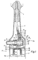
- Fig. 1 shows a section through an embodiment of the dispenser brush according to the invention.
- This embodiment illustrates a dishwashing brush and the greater part of the brush head 1, and the greater part of the reservoir 2 are omitted for clearness of the Figure.
- a conduit member in the form of a plastic tube 3 conveys detergent from the reservoir 2 to the brush head 1, in which one or more dispensing openings (not shown) are provided for dispensing the detergent to the bristles of the brush head.
- the piston pump 4 is placed in a part 5a of the handle 5 of the brush, which part is provided adjacent the brush head 1.
- the piston pump 4 comprises a piston member 6, a cylinder member 7 and a spring member in the form of a coil spring 8.
- the coil spring 8 is made of a rustproof material to resist the agents which pass through the pump.
- the spring 8 is placed between the bottom 9 of the cylinder member 7 and an abutment 10 on the piston member 6 so that a returning of the piston member to its position of rest is effected upon the termination of the compression stroke.
- piston pump 4 is arranged for a movement substantially normal to the longitudinal axis of the brush, as it appears from Fig. 1. Due to the fact that the piston member 6 comprises an actuator button 11, extending through an opening 12 in the wall 13 of the handle, it is very simple for the user to activate the piston pump 4, in dispensing a precisely dosed quantity of the agent to the head of the brush.
- the end 6a of the piston member 6 facing into the cylinder member 7 has a radially outwardly extending edge 14 which is in sealing contact with the wall 15 of the cylinder.
- the piston member 6 is provided with a protruding flange 16 defining the outward stroke of the piston, because the outer diameter of the flange 16 is greater than the diameter of the opening 12.
- the sidewall of the cylinder member 15 is provided with an inlet opening 17 and an outlet opening 18.
- the inlet opening is positioned in immediate vicinity of the edge 14 of the piston when the piston is affected solely by the spring 8 and is in its position of rest with the flange 16 abutting the inside of the wall 13 of the handle.
- the outlet opening 18 is positioned substantially at the position the sealing edge 14 occupies when the piston member 6 has finished the compression stroke.
- a hollow stub 19 surrounds the outlet opening and is provided with a flange 20.
- the flange 20 is intended for snap engagement with a groove 21 placed in one end 22 of a valve house 23 containing a closing member for the outlet opening.
- the closing member consists of a non-return valve unit 24 in the form of a valve body 25 made integrally with the spring member 26 and intended to abut against a valve seat 27 provided in the hollow stub 19 at the outlet opening 18.
- the spring member 26 of the unit 24 is made of tube pieces 27 which are mutually connected along a part 28 of their circumferences and which simultaneously are connected with the valve body 25 through a cross-arrangement 29 with an outer dimension substantially corresponding to the inner diameter of the valve house 23 for guiding the unit 24 in the valve house and so as to ensure the correct abutment of the valve body 25 against the valve seat 27.
- a supporting arrangement at the other end of the spring member 26 is manufactured with openings 31 to ensure the free passage of the agent out through an opening 32, passing through the bottom 33 of the valve house 23 and further through the plastic tube 3.
- the plastic tube 3 is secured to the valve house 23 by means of a hollow stub 34.
- the unit 24 thus provided is simple to manufacture by die casting because the thickness of all the walls is substantially identical. Moreover, the unit 24 is simple to assemble because the unit simply has to be placed in the valve house 23, which afterwards is firmly snapped onto the stub 19.
- the spring member 26 is compressed so that the valve body 25 presses against the valve seat 27 with a predetermined pressure.
- the non-return valve is positioned in the immediate vicinity of the cylinder member to eliminate the inexactness which may arse as the agent is conducted through a long flexible plastic tube, which might make a precise dosage impossible.
- non-return valve may in some situations be positioned near the dispensing openings in the brush head, but in such cases, conduit member which must be arranged between the cylinder member and the non-return valve, must have sufficient stiffness to be substantially un-expandable under the influence of the pressure which is caused by the piston pump.
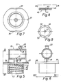
- the cylinder member is via a stub 35 made in one piece with a flange 36 for securing the cylinder member in the handle 5.
- the flange 36 is provided with a recess 37 which co-operates with a ridge 38 provided diametrically opposite the opening 12 to secure the actuator button 11 circumferentially with respect to the opening 12.
- the flange 36 is substantially circular, however, it is cut at 38 and 39 because the handle in the embodiment illustrated does not have a completely circular cross section area for receiving the flange in the assembled condition.
- the cut edges, which appear at 38 and 39 further contribute to a correct fixation of the cylinder member in the handle.
- two beads 40, 41 are arranged having a mutual distance substantially corresponding to the thickness of the flange 36.
- the bead 40 positioned nearest the part 5b of the handle is rounded so that the flange 36 relatively easily can be displaced over this bead.
- the second bead 41 is provided with a relatively sharp side edge to ensure that the flange is not displaced beyond this bead 41.
- the flange 36 comprises a member intended for connection with a member on the reservoir and provided in the form of an inner thread 42 in a tubular protrusion 43 on the flange.
- the inlet opening 17 is connected with the hollow interior of the stub 35 and opens through the flange 36. At the mouth it is surrounded by a protrusion 44 provided with a sharp edge 45.
- the reservoir 2 has a neck part 46 which is provided with an outer thread 47 intended for engagement with the thread 42. Between the outer edge of the neck part 46 of the flange 36 a flexible membrane 48 is provided, which is intended for venting the reservoir 2 when a quantity of the agent is being dispensed. This venting is intended to prevent a vacuum blocking of the delivery of the agent to the brush head.
- the membrane 48 At the outer circumference and at the area in front of the edge of the neck part 46 the membrane 48 has an upstanding edge 49 intended to abut against the flange 36 and provided with a plurality of radial openings 50. These radial openings 50 ensure that air may pass from the space between the two threads 42 and 47 to the space provided between the membrane 48 and the flange 36.
- a central opening 51 is provided in the membrane, which opening has a diameter less than the diameter of the sharp-edged, annular protrusion 44.
- one or more openings are provided in the tubular protrusion 43 in the immediate vicinity of the flange 36 for the passage of the air from the area outside the protrusion 43 to the area inside the protrusion in the immediate vicinity of the membrane.
- each of the parts of the dispenser brush is preferably manufactured with a substantially equal wall thickness whereby an advantageous of the manufacturing is achieved.
- the actuator button When mounting the pump member/flange unit in the handle, the actuator button is pressed down so that the piston member is moved inside the piston member and has a smaller radial extension than the flange, hereafter the unit is displaced through the handle until the flange abuts against the second bead 41. In this position the actuator button 11 is arranged in front of the opening 12 and due to the effect of the spring 8 it will be urged through the opening 12.
- the dosage takes place in that the user activates the actuator button 11 with the thumb while gripping around the part of the handle 5b facing away from the head of the brush and surrounding the reservoir 2 which may form a part of the handle or which reservoir may be placed inside the part of the handle 5b.
- the piston member 6 is depressed one or more times dependent upon the dosage required.
- the vacuum which is created in the reservoir 2 is equalized by passing between the threads 42 and 47 and through the openings 50 in the membrane and further through the slot created between the edge 45 and the membrane due to the pressure difference over the membrane. After the pressure equalizing is obtained the membrane again will abut against the edge 45, and in this way the agent in the reservoir 2 can not flow out into the space between the threads.
Landscapes
- Coating Apparatus (AREA)
- Containers And Packaging Bodies Having A Special Means To Remove Contents (AREA)
- Pens And Brushes (AREA)
- Fuel-Injection Apparatus (AREA)
- Apparatus For Radiation Diagnosis (AREA)
- Brushes (AREA)
Abstract
Description
- The present invention relates to a dispenser brush, intended for dispensing doses of an agent and comprising a reservoir for the agent, which reservoir is provided inside or forms a part of the handle of the dispenser brush, a brush head, a conduit member connecting the reservoir and one or more dispensing openings in the brush head and a dose member interposed between the reservoir and the dispensing openings in the brush head and consisting of a piston pump which comprises a piston member, a cylinder member and a spring member biasing the piston member in the direction opposite the compression stroke and which spring member provides for the returning of the piston member outwardly of the cylinder member to its position of rest, after the compression stroke of the piston member.
- A dispenser brush is known from No-A-146799.
- Dispenser brushes are known which have a reservoir for soap or another agent intended to be conveyed to the brush head and wherein said agent is dispensed dependent on a liquid flow passing through the handle of the brush to the brush head. Such brushes are used e.g. for car wash.
- At other occasions it is desirable to manufacture a brush wherein the agent to be conveyed to the brush head may be dispensed solely dependent on the wishes of using a greater or smaller dose. An example of such a brush is known e.g. from DE published application No. 2,328,823. This describes a car brush, wherein a valve arrangement makes it possible to dose an additive. However, it is not possible to effect this dosage with exactness.
- Moreover, it is also desirable to use a dosing in connection with brushes other than that type wherein a waterflow passes through the handle, e.g. in connection with brushes for dishwashing where the water is contained in a bowl, and brushes for car wash with the water contained in a bucket.
- Such a type of brush may also be used for personal hygiene or for sanitary purposes. The agents used in the brush may be in the form of low viscosity liquid agents or sluggish paste like agents.
- Examples of such brushes are known e.g. from DE published application No. 1,811,217. This describes a toothbrush with a toothpaste reservoir, wherein the toothpaste is conducted through a duct to nozzles in the brush head by a pump. However, this construction does not give a precise dosage.
- In GB published application No. 2,066,059 a construction is disclosed which, in a hairbrush, makes it possible to convey a hair treatment preparation directly from a reservoir in the brush head to the bristles by means of an associated dispensing member. However, this conveyance is unreliable too.
- Seeing that an unreliable dosage often may cause a poor result of the work conducted, it is desirable with a dispenser brush to obtain a precise dosing.
- In SE patent No. 439,726 a brush construction is described, which makes it possible to obtain a precise dosage of an agent by means of a piston pump. However, this construction requires a very accurate manufacturing and dimensioning of the individual elements forming parts of the dose mechanism, and the activation of the pump mechanism is difficult because the reservoir itself is to be displaced backwards and forwards inside the handle part to obtain the dispensing of the agent.
- Accordingly, it is the object of the present invention to provide a dispenser brush of the type mentioned by way of introduction which eliminates the above mentioned drawbacks associated with known dispenser brushes and which provides the above mentioned desirable advantages of a dosage which is precise and which is dispensed solely dependent on the wishes of the user, which dispenser brush may be made from simple elements making a simple assembling possible and which enables an easy, effortless activation of the pump mechanism.
- This object is achieved with a dispenser brush of the type mentioned by way of introduction and characterized in that the piston pump is arranged for movement in a direction substantially normal to the longitudinal axis of the brush, that the piston member comprises an actuator button extending through an opening in the wall of the handle, that the edge of the piston member which is facing into the cylinder member is in sealing contact with the wall of the cylinder, that the cylinder member has an inlet opening arranged in the side wall and provided in the immediate vicinity of the sealing edge of the piston member, when the piston member is in its position of rest and an outlet opening provided at said sealing edge when the piston member has performed the compression stroke, which outlet opening is surrounded by a stub provided with a flange, that the inlet opening is provided with a venting member and that the outlet opening is provided with a closing member.
- A dispenser brush according to the invention and as defined above is made of few individual parts all of which are relatively inexpensive elements. Even though only few elements are used in the dispenser brush a very secure operation and a precise dosage of the agent to be dispensed is obtained.
- With the dispenser brush a simple and quick assembling is obtained as an assembly consisting of the cylinder member, the piston member, the closing member for the outlet opening and the venting member for the inlet opening, in an assembled state, may be mounted in the handle of the dispenser brush without any risk of incorrect mounting. Moreover, the dispenser brush will be very simple to activate because the user, with a normal working grip around the handle, may activate the actuator button with the thumb and provide the dispensing in doses.
- The invention will now be further explained with reference to the accompanying drawing, in which
- Fig. 1
- is a fragmentary view, partly in section, of a dispenser brush intended for use as a dishwashing brush
- Fig. 2
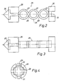
- is a view, on an enlarged scale, of an one-piece valve body and spring member for use in the dishwashing brush shown in Fig. 1,
- Fig. 3
- is a view of the element shown in Fig. 2, illustrated in a postion turned 90°,
- Fig. 4
- is a view of the element shown in Figs. 2 and 3, illustrated from the end where the valve body is placed,
- Fig. 5
- is a section, on another scale, through an assembly consisting of the cylinder member made integrally with a flange and an inner thread for fastening the reservoir,
- Fig. 6
- is a view of the assembly shown i Fig. 5 as seen according to section line VI-VI in Fig. 5,
- fig. 7
- is a view of the assembly shown in Figs. 5 and 6 as seen according to section line VII-VII in Fig. 6,
- fig. 8
- is a section through a membrane for venting the reservoir, and
- fig. 9
- is a view of the membrane shown in Fig. 8 as seen according to section line IX-IX.
- Fig. 1 shows a section through an embodiment of the dispenser brush according to the invention. This embodiment illustrates a dishwashing brush and the greater part of the brush head 1, and the greater part of the
reservoir 2 are omitted for clearness of the Figure. A conduit member in the form of aplastic tube 3 conveys detergent from thereservoir 2 to the brush head 1, in which one or more dispensing openings (not shown) are provided for dispensing the detergent to the bristles of the brush head. - Between the
reservoir 2 and the head 1 a pump member is inserted which is provided in the form of a piston pump 4. The piston pump 4 is placed in apart 5a of the handle 5 of the brush, which part is provided adjacent the brush head 1. The piston pump 4 comprises apiston member 6, a cylinder member 7 and a spring member in the form of acoil spring 8. Thecoil spring 8 is made of a rustproof material to resist the agents which pass through the pump. - The
spring 8 is placed between thebottom 9 of the cylinder member 7 and anabutment 10 on thepiston member 6 so that a returning of the piston member to its position of rest is effected upon the termination of the compression stroke. - For the ease of activation the piston pump 4 is arranged for a movement substantially normal to the longitudinal axis of the brush, as it appears from Fig. 1. Due to the fact that the
piston member 6 comprises anactuator button 11, extending through anopening 12 in thewall 13 of the handle, it is very simple for the user to activate the piston pump 4, in dispensing a precisely dosed quantity of the agent to the head of the brush. - The
end 6a of thepiston member 6 facing into the cylinder member 7 has a radially outwardly extendingedge 14 which is in sealing contact with thewall 15 of the cylinder. At the outer peripheri thepiston member 6 is provided with a protrudingflange 16 defining the outward stroke of the piston, because the outer diameter of theflange 16 is greater than the diameter of theopening 12. - The sidewall of the
cylinder member 15 is provided with an inlet opening 17 and an outlet opening 18. The inlet opening is positioned in immediate vicinity of theedge 14 of the piston when the piston is affected solely by thespring 8 and is in its position of rest with theflange 16 abutting the inside of thewall 13 of the handle. The outlet opening 18 is positioned substantially at the position the sealingedge 14 occupies when thepiston member 6 has finished the compression stroke. Ahollow stub 19 surrounds the outlet opening and is provided with aflange 20. Theflange 20 is intended for snap engagement with a groove 21 placed in oneend 22 of avalve house 23 containing a closing member for the outlet opening. The closing member consists of anon-return valve unit 24 in the form of avalve body 25 made integrally with thespring member 26 and intended to abut against avalve seat 27 provided in thehollow stub 19 at theoutlet opening 18. - As it especially occurs from Figs. 2, 3 and 4 the
spring member 26 of theunit 24 is made oftube pieces 27 which are mutually connected along apart 28 of their circumferences and which simultaneously are connected with thevalve body 25 through a cross-arrangement 29 with an outer dimension substantially corresponding to the inner diameter of thevalve house 23 for guiding theunit 24 in the valve house and so as to ensure the correct abutment of thevalve body 25 against thevalve seat 27. - A supporting arrangement at the other end of the
spring member 26 is manufactured withopenings 31 to ensure the free passage of the agent out through anopening 32, passing through the bottom 33 of thevalve house 23 and further through theplastic tube 3. Theplastic tube 3 is secured to thevalve house 23 by means of ahollow stub 34. Theunit 24 thus provided is simple to manufacture by die casting because the thickness of all the walls is substantially identical. Moreover, theunit 24 is simple to assemble because the unit simply has to be placed in thevalve house 23, which afterwards is firmly snapped onto thestub 19. - Hereby, the
spring member 26 is compressed so that thevalve body 25 presses against thevalve seat 27 with a predetermined pressure. The non-return valve is positioned in the immediate vicinity of the cylinder member to eliminate the inexactness which may arse as the agent is conducted through a long flexible plastic tube, which might make a precise dosage impossible. - However, the non-return valve may in some situations be positioned near the dispensing openings in the brush head, but in such cases, conduit member which must be arranged between the cylinder member and the non-return valve, must have sufficient stiffness to be substantially un-expandable under the influence of the pressure which is caused by the piston pump.
- The cylinder member is via a
stub 35 made in one piece with aflange 36 for securing the cylinder member in the handle 5. At the circumference theflange 36 is provided with arecess 37 which co-operates with aridge 38 provided diametrically opposite theopening 12 to secure theactuator button 11 circumferentially with respect to theopening 12. Theflange 36 is substantially circular, however, it is cut at 38 and 39 because the handle in the embodiment illustrated does not have a completely circular cross section area for receiving the flange in the assembled condition. The cut edges, which appear at 38 and 39 further contribute to a correct fixation of the cylinder member in the handle. In the handle 5 twobeads flange 36. Thebead 40 positioned nearest thepart 5b of the handle is rounded so that theflange 36 relatively easily can be displaced over this bead. At the side facing thefirst bead 40, thesecond bead 41 is provided with a relatively sharp side edge to ensure that the flange is not displaced beyond thisbead 41. - Furthermore, the
flange 36 comprises a member intended for connection with a member on the reservoir and provided in the form of an inner thread 42 in a tubular protrusion 43 on the flange. Theinlet opening 17 is connected with the hollow interior of thestub 35 and opens through theflange 36. At the mouth it is surrounded by aprotrusion 44 provided with asharp edge 45. - The
reservoir 2 has aneck part 46 which is provided with an outer thread 47 intended for engagement with the thread 42. Between the outer edge of theneck part 46 of the flange 36 aflexible membrane 48 is provided, which is intended for venting thereservoir 2 when a quantity of the agent is being dispensed. This venting is intended to prevent a vacuum blocking of the delivery of the agent to the brush head. At the outer circumference and at the area in front of the edge of theneck part 46 themembrane 48 has anupstanding edge 49 intended to abut against theflange 36 and provided with a plurality ofradial openings 50. Theseradial openings 50 ensure that air may pass from the space between the two threads 42 and 47 to the space provided between themembrane 48 and theflange 36. Acentral opening 51 is provided in the membrane, which opening has a diameter less than the diameter of the sharp-edged,annular protrusion 44. - Due to the fact that the height of the
annular protrusion 44 of the flange is greater than the height of the protrudingedge 49 of themembrane 48, the membrane normally rests against theedge 45 of thecircular protrusion 44 of the flange. However, a partial vacuum occuring in thereservoir 2 by dosing of the agent is sufficient to lift theflexible membrane 48 away from theedge 45 so that a pressure equalizing effect is obtained and thereby a vacuum blocking is prevented. - In another embodiment than the one shown one or more openings are provided in the tubular protrusion 43 in the immediate vicinity of the
flange 36 for the passage of the air from the area outside the protrusion 43 to the area inside the protrusion in the immediate vicinity of the membrane. - In a construction according to the invention, each of the parts of the dispenser brush is preferably manufactured with a substantially equal wall thickness whereby an advantageous of the manufacturing is achieved.
- When mounting the pump member/flange unit in the handle, the actuator button is pressed down so that the piston member is moved inside the piston member and has a smaller radial extension than the flange, hereafter the unit is displaced through the handle until the flange abuts against the
second bead 41. In this position theactuator button 11 is arranged in front of theopening 12 and due to the effect of thespring 8 it will be urged through theopening 12. - The dosage takes place in that the user activates the
actuator button 11 with the thumb while gripping around the part of thehandle 5b facing away from the head of the brush and surrounding thereservoir 2 which may form a part of the handle or which reservoir may be placed inside the part of thehandle 5b. Hereby, thepiston member 6 is depressed one or more times dependent upon the dosage required. - When the sealing
edge 14 of the piston member passes theinlet opening 17, this inlet opening will be closed and a further activation of the piston member increases the pressure of the agent inside the cylinder member. Hereby, an increase of pressure occurs which lifts thevalve body 25 away from theseat 27 and allows the passage of the agent through thenon-return valve 23 and further on to the brush head 1. By an appropriate dimensioning of the diameter of the cylinder member and the stroke of the piston member, it is possible on beforehand to chose the volume to be dosed at each compression stroke. When the piston member has finished the compression stroke and the user relieves the pressure on theactuator button 11, thespring 8 provides the returning of the piston member and at this time thevalve body 25 again will abut against theseat 27 and in this way a vacuum is created in the cylinder chamber. This vacuum will be equalized by agent flowing from the reservoir and into the cylinder member for filling the chamber, but not until theedge 14 of the valve body has passed theinlet opening 17. - The vacuum which is created in the
reservoir 2 is equalized by passing between the threads 42 and 47 and through theopenings 50 in the membrane and further through the slot created between theedge 45 and the membrane due to the pressure difference over the membrane. After the pressure equalizing is obtained the membrane again will abut against theedge 45, and in this way the agent in thereservoir 2 can not flow out into the space between the threads.
Claims (8)
Priority Applications (1)
| Application Number | Priority Date | Filing Date | Title |
|---|---|---|---|
| AT88902823T ATE65168T1 (en) | 1987-03-26 | 1988-03-25 | DISPENSER BRUSH. |
Applications Claiming Priority (2)
| Application Number | Priority Date | Filing Date | Title |
|---|---|---|---|
| DK1559/87 | 1987-03-26 | ||
| DK155987A DK155111C (en) | 1987-03-26 | 1987-03-26 | Dispenser |
Publications (2)
| Publication Number | Publication Date |
|---|---|
| EP0306516A1 EP0306516A1 (en) | 1989-03-15 |
| EP0306516B1 true EP0306516B1 (en) | 1991-07-17 |
Family
ID=8106060
Family Applications (1)
| Application Number | Title | Priority Date | Filing Date |
|---|---|---|---|
| EP88902823A Expired - Lifetime EP0306516B1 (en) | 1987-03-26 | 1988-03-25 | Dispenser brush |
Country Status (7)
| Country | Link |
|---|---|
| US (1) | US4893957A (en) |
| EP (1) | EP0306516B1 (en) |
| JP (1) | JPH01503602A (en) |
| AU (1) | AU599785B2 (en) |
| DK (1) | DK155111C (en) |
| FI (1) | FI885485A0 (en) |
| WO (1) | WO1988007339A1 (en) |
Families Citing this family (20)
| Publication number | Priority date | Publication date | Assignee | Title |
|---|---|---|---|---|
| US4938621A (en) * | 1988-05-03 | 1990-07-03 | Okanagan House Inc. | Hair brush and mousse dispensing device |
| FR2734695B1 (en) * | 1995-05-29 | 1997-08-14 | Martin Joseph | COMPACT ASSEMBLY: TOOTHBRUSH + LIQUID TOOTHPASTE |
| FI956061A (en) * | 1995-12-15 | 1997-06-16 | Puurunen Juha Pekka | Pump Toothbrush |
| IL116921A (en) | 1996-01-26 | 2000-11-21 | Yissum Res Dev Co | Electrochemical system for determination of an analyte in a liquid medium |
| US5649334A (en) * | 1996-03-07 | 1997-07-22 | Henriquez; Jorge De Jesus Matias | Water and soap dispensing scrubber apparatus |
| GB9717429D0 (en) * | 1997-08-19 | 1997-10-22 | Veresk Biosystems Ltd | Brush |
| DE29720740U1 (en) * | 1997-11-22 | 1998-02-12 | Zylmann Peter | Brush filled with detergent |
| AU694910B3 (en) * | 1997-11-25 | 1998-07-30 | Shieh-Yen Huang | Household cleaning equipment |
| US6210064B1 (en) | 1998-12-28 | 2001-04-03 | General Housewares Corp. | Soap-fillable brush with sealed actuator |
| US6250833B1 (en) | 2000-01-17 | 2001-06-26 | General Housewares Corp. | Soap-dispensing kitchen brush |
| US6623201B2 (en) * | 2000-09-08 | 2003-09-23 | John Francois Brumlik | Cleaning device and method of use |
| US7244073B2 (en) * | 2003-05-27 | 2007-07-17 | Trocino Richard B | Travel toothbrush assembly |
| US7641410B2 (en) * | 2006-06-16 | 2010-01-05 | Frazell Dale M | Toothbrush with dentifrice dispenser |
| US20100067972A1 (en) * | 2008-09-18 | 2010-03-18 | Ashworth Robert Scott | Grill cleaning utensil |
| WO2010118712A1 (en) * | 2009-04-14 | 2010-10-21 | Karan Dadgar | Liquid pump appliance for dosing |
| TWI413513B (en) | 2010-01-29 | 2013-11-01 | Colgate Palmolive Co | Oral care fluid delivery system |
| CN102267436A (en) * | 2011-05-31 | 2011-12-07 | 大连交通大学 | Portable vehicle washing device |
| US9247805B1 (en) | 2011-09-09 | 2016-02-02 | Solutionworks Llc | Hairbrush with liquid dispensing apparatus |
| USD805308S1 (en) | 2011-11-29 | 2017-12-19 | FC Brands Limited | Combined foaming brush and housing |
| US20200015580A1 (en) * | 2018-07-12 | 2020-01-16 | Janice Miranda | Spray Dispensing Cleaning Implement |
Family Cites Families (10)
| Publication number | Priority date | Publication date | Assignee | Title |
|---|---|---|---|---|
| US1446967A (en) * | 1921-10-14 | 1923-02-27 | Leslie C Flewelling | Fountain brush |
| US1811512A (en) * | 1929-09-16 | 1931-06-23 | Marsh Stencil Machine Company | Fountain brush |
| US2302062A (en) * | 1941-09-26 | 1942-11-17 | Daniel H Schweyer | Liquid pressure marking device |
| US2563842A (en) * | 1947-07-05 | 1951-08-14 | Everett A Johnson | Spray-roller dispenser |
| US2772430A (en) * | 1953-07-13 | 1956-12-04 | Irving J Moritt | Dish cleaning device with detergent feed |
| US3186024A (en) * | 1961-10-26 | 1965-06-01 | Marsh Stencil Machine Company | Fountain roller |
| NO146799L (en) * | 1976-06-08 | 1900-01-01 | ||
| GB2066059A (en) * | 1979-12-05 | 1981-07-08 | Lung Fu Fang | Comb or brush |
| DE3636013A1 (en) * | 1986-10-23 | 1988-05-05 | Henkel Kgaa | DISPENSER FOR PASTE-LIKE PRODUCT |
| EP0264824B1 (en) * | 1986-10-23 | 1990-08-08 | Henkel Kommanditgesellschaft auf Aktien | Dispenser for pastry products |
-
1987
- 1987-03-26 DK DK155987A patent/DK155111C/en not_active IP Right Cessation
-
1988
- 1988-03-25 AU AU15467/88A patent/AU599785B2/en not_active Ceased
- 1988-03-25 EP EP88902823A patent/EP0306516B1/en not_active Expired - Lifetime
- 1988-03-25 JP JP63502889A patent/JPH01503602A/en active Pending
- 1988-03-25 WO PCT/DK1988/000051 patent/WO1988007339A1/en active IP Right Grant
- 1988-03-25 US US07/275,058 patent/US4893957A/en not_active Expired - Fee Related
- 1988-11-25 FI FI885485A patent/FI885485A0/en not_active Application Discontinuation
Also Published As
| Publication number | Publication date |
|---|---|
| JPH01503602A (en) | 1989-12-07 |
| DK155111B (en) | 1989-02-13 |
| US4893957A (en) | 1990-01-16 |
| FI885485A (en) | 1988-11-25 |
| DK155987D0 (en) | 1987-03-26 |
| AU599785B2 (en) | 1990-07-26 |
| EP0306516A1 (en) | 1989-03-15 |
| AU1546788A (en) | 1988-11-02 |
| WO1988007339A1 (en) | 1988-10-06 |
| FI885485A0 (en) | 1988-11-25 |
| DK155987A (en) | 1988-09-27 |
| DK155111C (en) | 1989-07-03 |
Similar Documents
| Publication | Publication Date | Title |
|---|---|---|
| EP0306516B1 (en) | Dispenser brush | |
| RU2191533C2 (en) | Brush | |
| US7520406B2 (en) | Device for dispensing a controlled dose of a flowable material | |
| US5158383A (en) | Paste dispensing brush | |
| US4236651A (en) | Dispenser device with valve piston pump | |
| US2743042A (en) | Fountain toothbrush | |
| US4521128A (en) | Disposable toothbrush with cap | |
| EP1585602B1 (en) | Simplified sprayer device | |
| US20040159332A1 (en) | Cleaning device and method of use | |
| EP0435341A2 (en) | Shower utensil having brush | |
| EP0123152B1 (en) | Cleaning system | |
| US7837403B2 (en) | Shampooing brush | |
| NZ229487A (en) | Powder dispensing brush | |
| US5443321A (en) | Dispensing brush head | |
| US20080023576A1 (en) | Shower | |
| US8308385B2 (en) | Atomizer having auxiliary dispenser and manufacturing method of the same | |
| US4008834A (en) | Tip seal for a dispensing valve | |
| FI76712B (en) | HANDMANOEVRERAD SPRAYANORDNING. | |
| EP0193299B1 (en) | Brush for applying material in liquid or emulsion form | |
| US3242928A (en) | Reciprocating aerosol toothbrush with self-sealing elastic valve means | |
| US5332129A (en) | Soap dispenser assembly | |
| EP0409594A1 (en) | Toothbrush with toothpaste dispenser | |
| US20240000222A1 (en) | Oral Care Implement with Fluid Dispensing System | |
| WO2008118657A1 (en) | Fluid dispensing apparatus | |
| EP1533247B1 (en) | Pump action dispenser |
Legal Events
| Date | Code | Title | Description |
|---|---|---|---|
| PUAI | Public reference made under article 153(3) epc to a published international application that has entered the european phase |
Free format text: ORIGINAL CODE: 0009012 |
|
| AK | Designated contracting states |
Kind code of ref document: A1 Designated state(s): AT BE CH DE FR GB IT LI LU NL SE |
|
| 17P | Request for examination filed |
Effective date: 19890331 |
|
| DET | De: translation of patent claims | ||
| 17Q | First examination report despatched |
Effective date: 19900928 |
|
| GRAA | (expected) grant |
Free format text: ORIGINAL CODE: 0009210 |
|
| AK | Designated contracting states |
Kind code of ref document: B1 Designated state(s): AT BE CH DE FR GB IT LI LU NL SE |
|
| PG25 | Lapsed in a contracting state [announced via postgrant information from national office to epo] |
Ref country code: IT Free format text: LAPSE BECAUSE OF FAILURE TO SUBMIT A TRANSLATION OF THE DESCRIPTION OR TO PAY THE FEE WITHIN THE PRE;WARNING: LAPSES OF ITALIAN PATENTS WITH EFFECTIVE DATE BEFORE 2007 MAY HAVE OCCURRED AT ANY TIME BEFORE 2007. THE CORRECT EFFECTIVE DATE MAY BE DIFFERENT FROM THE ONE RECORDED.SCRIBED TIME-LIMIT Effective date: 19910717 Ref country code: BE Effective date: 19910717 Ref country code: AT Effective date: 19910717 Ref country code: LI Effective date: 19910717 Ref country code: NL Effective date: 19910717 Ref country code: CH Effective date: 19910717 Ref country code: SE Effective date: 19910717 |
|
| REF | Corresponds to: |
Ref document number: 65168 Country of ref document: AT Date of ref document: 19910815 Kind code of ref document: T |
|
| REF | Corresponds to: |
Ref document number: 3863723 Country of ref document: DE Date of ref document: 19910822 |
|
| REG | Reference to a national code |
Ref country code: CH Ref legal event code: PL |
|
| ET | Fr: translation filed | ||
| NLV1 | Nl: lapsed or annulled due to failure to fulfill the requirements of art. 29p and 29m of the patents act | ||
| PGFP | Annual fee paid to national office [announced via postgrant information from national office to epo] |
Ref country code: GB Payment date: 19920318 Year of fee payment: 5 |
|
| PG25 | Lapsed in a contracting state [announced via postgrant information from national office to epo] |
Ref country code: LU Free format text: LAPSE BECAUSE OF NON-PAYMENT OF DUE FEES Effective date: 19920331 |
|
| PLBE | No opposition filed within time limit |
Free format text: ORIGINAL CODE: 0009261 |
|
| STAA | Information on the status of an ep patent application or granted ep patent |
Free format text: STATUS: NO OPPOSITION FILED WITHIN TIME LIMIT |
|
| 26N | No opposition filed | ||
| PG25 | Lapsed in a contracting state [announced via postgrant information from national office to epo] |
Ref country code: GB Effective date: 19930325 |
|
| PGFP | Annual fee paid to national office [announced via postgrant information from national office to epo] |
Ref country code: FR Payment date: 19930326 Year of fee payment: 6 |
|
| PGFP | Annual fee paid to national office [announced via postgrant information from national office to epo] |
Ref country code: DE Payment date: 19930528 Year of fee payment: 6 |
|
| GBPC | Gb: european patent ceased through non-payment of renewal fee |
Effective date: 19930325 |
|
| PG25 | Lapsed in a contracting state [announced via postgrant information from national office to epo] |
Ref country code: FR Effective date: 19941130 |
|
| PG25 | Lapsed in a contracting state [announced via postgrant information from national office to epo] |
Ref country code: DE Effective date: 19941201 |
|
| REG | Reference to a national code |
Ref country code: FR Ref legal event code: ST |