EP0306110B1 - Method for manufacture of a coriolis flow meter - Google Patents
Method for manufacture of a coriolis flow meter Download PDFInfo
- Publication number
- EP0306110B1 EP0306110B1 EP88201881A EP88201881A EP0306110B1 EP 0306110 B1 EP0306110 B1 EP 0306110B1 EP 88201881 A EP88201881 A EP 88201881A EP 88201881 A EP88201881 A EP 88201881A EP 0306110 B1 EP0306110 B1 EP 0306110B1
- Authority
- EP
- European Patent Office
- Prior art keywords
- tube
- value
- specimen
- modulus
- young
- Prior art date
- Legal status (The legal status is an assumption and is not a legal conclusion. Google has not performed a legal analysis and makes no representation as to the accuracy of the status listed.)
- Expired - Lifetime
Links
- 238000000034 method Methods 0.000 title claims description 39
- 238000004519 manufacturing process Methods 0.000 title claims description 5
- 238000012360 testing method Methods 0.000 claims description 26
- 239000000463 material Substances 0.000 claims description 13
- 239000006185 dispersion Substances 0.000 claims description 9
- 238000010348 incorporation Methods 0.000 claims 1
- 229910052751 metal Inorganic materials 0.000 description 23
- 239000002184 metal Substances 0.000 description 23
- POIUWJQBRNEFGX-XAMSXPGMSA-N cathelicidin Chemical compound C([C@@H](C(=O)N[C@@H](CCCNC(N)=N)C(=O)N[C@@H](CCCCN)C(=O)N[C@@H](CO)C(=O)N[C@@H](CCCCN)C(=O)N[C@@H](CCC(O)=O)C(=O)N[C@@H](CCCCN)C(=O)N[C@@H]([C@@H](C)CC)C(=O)NCC(=O)N[C@@H](CCCCN)C(=O)N[C@@H](CCC(O)=O)C(=O)N[C@@H](CC=1C=CC=CC=1)C(=O)N[C@@H](CCCCN)C(=O)N[C@@H](CCCNC(N)=N)C(=O)N[C@@H]([C@@H](C)CC)C(=O)N[C@@H](C(C)C)C(=O)N[C@@H](CCC(N)=O)C(=O)N[C@@H](CCCNC(N)=N)C(=O)N[C@@H]([C@@H](C)CC)C(=O)N[C@@H](CCCCN)C(=O)N[C@@H](CC(O)=O)C(=O)N[C@@H](CC=1C=CC=CC=1)C(=O)N[C@@H](CC(C)C)C(=O)N[C@@H](CCCNC(N)=N)C(=O)N[C@@H](CC(N)=O)C(=O)N[C@@H](CC(C)C)C(=O)N[C@@H](C(C)C)C(=O)N1[C@@H](CCC1)C(=O)N[C@@H](CCCNC(N)=N)C(=O)N[C@@H]([C@@H](C)O)C(=O)N[C@@H](CCC(O)=O)C(=O)N[C@@H](CO)C(O)=O)NC(=O)[C@H](CC=1C=CC=CC=1)NC(=O)[C@H](CC(O)=O)NC(=O)CNC(=O)[C@H](CC(C)C)NC(=O)[C@@H](N)CC(C)C)C1=CC=CC=C1 POIUWJQBRNEFGX-XAMSXPGMSA-N 0.000 description 16
- 238000005259 measurement Methods 0.000 description 9
- 230000000694 effects Effects 0.000 description 7
- 229910000831 Steel Inorganic materials 0.000 description 6
- 239000012530 fluid Substances 0.000 description 6
- 239000010959 steel Substances 0.000 description 6
- 229910045601 alloy Inorganic materials 0.000 description 5
- 239000000956 alloy Substances 0.000 description 5
- 229910052782 aluminium Inorganic materials 0.000 description 5
- XAGFODPZIPBFFR-UHFFFAOYSA-N aluminium Chemical compound [Al] XAGFODPZIPBFFR-UHFFFAOYSA-N 0.000 description 5
- 230000001934 delay Effects 0.000 description 5
- 239000006260 foam Substances 0.000 description 4
- 229910000856 hastalloy Inorganic materials 0.000 description 4
- 230000001902 propagating effect Effects 0.000 description 4
- 229910001220 stainless steel Inorganic materials 0.000 description 4
- 239000010935 stainless steel Substances 0.000 description 4
- 238000009864 tensile test Methods 0.000 description 4
- 238000005452 bending Methods 0.000 description 3
- 230000006835 compression Effects 0.000 description 3
- 238000007906 compression Methods 0.000 description 3
- 238000012937 correction Methods 0.000 description 3
- WABPQHHGFIMREM-YPZZEJLDSA-N lead-205 Chemical compound [205Pb] WABPQHHGFIMREM-YPZZEJLDSA-N 0.000 description 3
- 230000010355 oscillation Effects 0.000 description 3
- 238000003070 Statistical process control Methods 0.000 description 2
- 238000013459 approach Methods 0.000 description 2
- TZCXTZWJZNENPQ-UHFFFAOYSA-L barium sulfate Chemical compound [Ba+2].[O-]S([O-])(=O)=O TZCXTZWJZNENPQ-UHFFFAOYSA-L 0.000 description 2
- 238000004364 calculation method Methods 0.000 description 2
- 230000001419 dependent effect Effects 0.000 description 2
- 238000010586 diagram Methods 0.000 description 2
- 238000000611 regression analysis Methods 0.000 description 2
- 239000002023 wood Substances 0.000 description 2
- CWYNVVGOOAEACU-UHFFFAOYSA-N Fe2+ Chemical compound [Fe+2] CWYNVVGOOAEACU-UHFFFAOYSA-N 0.000 description 1
- RTAQQCXQSZGOHL-UHFFFAOYSA-N Titanium Chemical compound [Ti] RTAQQCXQSZGOHL-UHFFFAOYSA-N 0.000 description 1
- 238000005219 brazing Methods 0.000 description 1
- 239000013078 crystal Substances 0.000 description 1
- 238000005520 cutting process Methods 0.000 description 1
- 230000003111 delayed effect Effects 0.000 description 1
- 238000001514 detection method Methods 0.000 description 1
- 238000005553 drilling Methods 0.000 description 1
- 239000003292 glue Substances 0.000 description 1
- 229910001026 inconel Inorganic materials 0.000 description 1
- 238000002347 injection Methods 0.000 description 1
- 239000007924 injection Substances 0.000 description 1
- 238000009659 non-destructive testing Methods 0.000 description 1
- 230000000644 propagated effect Effects 0.000 description 1
- 238000010079 rubber tapping Methods 0.000 description 1
- 238000006748 scratching Methods 0.000 description 1
- 230000002393 scratching effect Effects 0.000 description 1
- 230000035945 sensitivity Effects 0.000 description 1
- 230000035939 shock Effects 0.000 description 1
- 239000007787 solid Substances 0.000 description 1
- 229910001256 stainless steel alloy Inorganic materials 0.000 description 1
- 230000003068 static effect Effects 0.000 description 1
- 229910052719 titanium Inorganic materials 0.000 description 1
- 239000010936 titanium Substances 0.000 description 1
- 230000001960 triggered effect Effects 0.000 description 1
- 238000003466 welding Methods 0.000 description 1
Images



Classifications
-
- G—PHYSICS
- G01—MEASURING; TESTING
- G01F—MEASURING VOLUME, VOLUME FLOW, MASS FLOW OR LIQUID LEVEL; METERING BY VOLUME
- G01F1/00—Measuring the volume flow or mass flow of fluid or fluent solid material wherein the fluid passes through a meter in a continuous flow
- G01F1/76—Devices for measuring mass flow of a fluid or a fluent solid material
- G01F1/78—Direct mass flowmeters
- G01F1/80—Direct mass flowmeters operating by measuring pressure, force, momentum, or frequency of a fluid flow to which a rotational movement has been imparted
- G01F1/84—Coriolis or gyroscopic mass flowmeters
- G01F1/8404—Coriolis or gyroscopic mass flowmeters details of flowmeter manufacturing methods
-
- G—PHYSICS
- G01—MEASURING; TESTING
- G01F—MEASURING VOLUME, VOLUME FLOW, MASS FLOW OR LIQUID LEVEL; METERING BY VOLUME
- G01F1/00—Measuring the volume flow or mass flow of fluid or fluent solid material wherein the fluid passes through a meter in a continuous flow
- G01F1/76—Devices for measuring mass flow of a fluid or a fluent solid material
- G01F1/78—Direct mass flowmeters
- G01F1/80—Direct mass flowmeters operating by measuring pressure, force, momentum, or frequency of a fluid flow to which a rotational movement has been imparted
- G01F1/84—Coriolis or gyroscopic mass flowmeters
- G01F1/8409—Coriolis or gyroscopic mass flowmeters constructional details
- G01F1/8413—Coriolis or gyroscopic mass flowmeters constructional details means for influencing the flowmeter's motional or vibrational behaviour, e.g., conduit support or fixing means, or conduit attachments
-
- G—PHYSICS
- G01—MEASURING; TESTING
- G01F—MEASURING VOLUME, VOLUME FLOW, MASS FLOW OR LIQUID LEVEL; METERING BY VOLUME
- G01F1/00—Measuring the volume flow or mass flow of fluid or fluent solid material wherein the fluid passes through a meter in a continuous flow
- G01F1/76—Devices for measuring mass flow of a fluid or a fluent solid material
- G01F1/78—Direct mass flowmeters
- G01F1/80—Direct mass flowmeters operating by measuring pressure, force, momentum, or frequency of a fluid flow to which a rotational movement has been imparted
- G01F1/84—Coriolis or gyroscopic mass flowmeters
- G01F1/8409—Coriolis or gyroscopic mass flowmeters constructional details
- G01F1/8427—Coriolis or gyroscopic mass flowmeters constructional details detectors
-
- G—PHYSICS
- G01—MEASURING; TESTING
- G01F—MEASURING VOLUME, VOLUME FLOW, MASS FLOW OR LIQUID LEVEL; METERING BY VOLUME
- G01F1/00—Measuring the volume flow or mass flow of fluid or fluent solid material wherein the fluid passes through a meter in a continuous flow
- G01F1/76—Devices for measuring mass flow of a fluid or a fluent solid material
- G01F1/78—Direct mass flowmeters
- G01F1/80—Direct mass flowmeters operating by measuring pressure, force, momentum, or frequency of a fluid flow to which a rotational movement has been imparted
- G01F1/84—Coriolis or gyroscopic mass flowmeters
- G01F1/8409—Coriolis or gyroscopic mass flowmeters constructional details
- G01F1/8431—Coriolis or gyroscopic mass flowmeters constructional details electronic circuits
-
- G—PHYSICS
- G01—MEASURING; TESTING
- G01F—MEASURING VOLUME, VOLUME FLOW, MASS FLOW OR LIQUID LEVEL; METERING BY VOLUME
- G01F1/00—Measuring the volume flow or mass flow of fluid or fluent solid material wherein the fluid passes through a meter in a continuous flow
- G01F1/76—Devices for measuring mass flow of a fluid or a fluent solid material
- G01F1/78—Direct mass flowmeters
- G01F1/80—Direct mass flowmeters operating by measuring pressure, force, momentum, or frequency of a fluid flow to which a rotational movement has been imparted
- G01F1/84—Coriolis or gyroscopic mass flowmeters
- G01F1/8409—Coriolis or gyroscopic mass flowmeters constructional details
- G01F1/8436—Coriolis or gyroscopic mass flowmeters constructional details signal processing
-
- G—PHYSICS
- G01—MEASURING; TESTING
- G01F—MEASURING VOLUME, VOLUME FLOW, MASS FLOW OR LIQUID LEVEL; METERING BY VOLUME
- G01F1/00—Measuring the volume flow or mass flow of fluid or fluent solid material wherein the fluid passes through a meter in a continuous flow
- G01F1/76—Devices for measuring mass flow of a fluid or a fluent solid material
- G01F1/78—Direct mass flowmeters
- G01F1/80—Direct mass flowmeters operating by measuring pressure, force, momentum, or frequency of a fluid flow to which a rotational movement has been imparted
- G01F1/84—Coriolis or gyroscopic mass flowmeters
- G01F1/845—Coriolis or gyroscopic mass flowmeters arrangements of measuring means, e.g., of measuring conduits
- G01F1/8468—Coriolis or gyroscopic mass flowmeters arrangements of measuring means, e.g., of measuring conduits vibrating measuring conduits
-
- G—PHYSICS
- G01—MEASURING; TESTING
- G01F—MEASURING VOLUME, VOLUME FLOW, MASS FLOW OR LIQUID LEVEL; METERING BY VOLUME
- G01F25/00—Testing or calibration of apparatus for measuring volume, volume flow or liquid level or for metering by volume
- G01F25/10—Testing or calibration of apparatus for measuring volume, volume flow or liquid level or for metering by volume of flowmeters
-
- G—PHYSICS
- G01—MEASURING; TESTING
- G01N—INVESTIGATING OR ANALYSING MATERIALS BY DETERMINING THEIR CHEMICAL OR PHYSICAL PROPERTIES
- G01N29/00—Investigating or analysing materials by the use of ultrasonic, sonic or infrasonic waves; Visualisation of the interior of objects by transmitting ultrasonic or sonic waves through the object
- G01N29/04—Analysing solids
- G01N29/045—Analysing solids by imparting shocks to the workpiece and detecting the vibrations or the acoustic waves caused by the shocks
-
- G—PHYSICS
- G01—MEASURING; TESTING
- G01N—INVESTIGATING OR ANALYSING MATERIALS BY DETERMINING THEIR CHEMICAL OR PHYSICAL PROPERTIES
- G01N29/00—Investigating or analysing materials by the use of ultrasonic, sonic or infrasonic waves; Visualisation of the interior of objects by transmitting ultrasonic or sonic waves through the object
- G01N29/04—Analysing solids
- G01N29/07—Analysing solids by measuring propagation velocity or propagation time of acoustic waves
-
- G—PHYSICS
- G01—MEASURING; TESTING
- G01N—INVESTIGATING OR ANALYSING MATERIALS BY DETERMINING THEIR CHEMICAL OR PHYSICAL PROPERTIES
- G01N2291/00—Indexing codes associated with group G01N29/00
- G01N2291/26—Scanned objects
- G01N2291/263—Surfaces
- G01N2291/2634—Surfaces cylindrical from outside
Definitions
- the invention relates to a method of manufacturing a Coriolis mass flow rate meter, and in particular for evaluating metal tubes to be used as flow tubes in a Coriolis mass flow rate meter.
- Coriolis mass flow rate meters are used to measure the mass flow of a process fluid.
- one typical type of Coriolis mass flow rate meter contains two parallel flow conduits, each typically being a U-shaped metal tube.
- Each metal tube is driven to oscillate about an axis to create a rotational frame of reference.
- this axis can be termed the bending axis.
- the above-described Coriolis mass flow rate meters often required a zero-level offset adjustment.
- This offset adjustment properly calibrates the meter by reducing the measured mass flow rate to zero when no fluid flows through the meter.
- the zero-level offset adjustment value can be large in many cases and, in addition, fluctuate between various values when the meter is in use. The source of this large zero-level offset adjustment value and its fluctuation has not been recognized in the prior art.
- the measured value changes if the clamp is tightened or loosened.
- a second "axial tensile test” requires that a specimen be clamped at both ends. The specimen is pulled and Young's Modulus is calculated using the measured value of the force required to extend the specimen a specified distance. Unfortunately, because the cross-sectional area of the tube is not uniform along its length, the measured value for Young's Modulus can vary at least three percent.
- a "cantilever beam free vibration test” the specimen is clamped at one end. The specimen is then displaced by impact at, for example, the free end and the natural frequency of oscillation thereof is measured. Young's Modulus is then calculated using the measured value of the natural frequency.
- a drawback of the "cantilever beam free vibration test” is that the results are sensitive to end effects, i.e., the measured value of Young's Modulus changes with variations in clamping force.
- a "suspended bar test” requires that a specimen be hung or suspended from, for example, a line and an accelerometer be affixed to one end of the specimen. The suspended specimen is then struck with a hammer at, for example, its other end to excite axial or longitudinal oscillations therein. The natural frequency of this mode of oscillation is measured and Young's Modulus calculated using the measured value of the natural frequency.
- the invention provides an accurate method for determing a value of Young's Modulus of tubular specimens, the measuring results being independent of the constructional pecularities of a test fixture to be used and further independent of the length of the tubular specimen to be measured.
- the measuring accuracy of a Coriolis mass flow rate meter can be further increased by matching two tubular specimen, possessing associated values of Young's Modulus determined according to the above method.
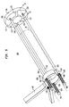
- FIG. 1 shows, in pictorial form, a preferred embodiment of an apparatus used in determining Young's Modulus of a tube in accordance with the present invention.
- the tube can be of various lengths and diameter. If discontinuities, such as kinks, nicks, or deep scratches, are present in the tube, it is believed that these discontinuities lead to longer transit times for the stress waves which will lower the value of Young's Modulus.
- instrumented hammer 12 has accelerometer 14 affixed to the head of the hammer. Accelerometer 14 is connected via lead 15 to circuitry 16 whose function will be described in detailed below.
- Striking cap 18 is affixed to one end of tube 20.
- Cap 22 is affixed to the other end. Accelerometer 24 is affixed to cap 22 and is connected to circuitry 16 via lead 26.
- longitudinal waves also known as compressional or dilatational waves
- shear waves are generated, both of which types of waves propagate in the body.
- the longitudinal waves are referred to as P-waves and the shear waves are referred to as S-waves.
- the velocity of propagation of P-waves in the elastic body is faster than that of S-waves.
- the amplitudes of the S-waves are greater than those of the P-waves.
- embodiments of the present invention detect either P-waves or S-waves, to assure maximum accuracy of the resulting measurements, the measurement of P-waves is preferred.
- the increased accuracy results because the detected wave front is relatively sharp since it only contains energy from one type of wave, namely, P-waves.
- the detected wave front would not be as sharp because, in general, it would contain some residual energy from the P-waves along with energy from the S-waves. This would therefore limit the repeatability of the resulting measurements.
- cap 18 helps to ensure that the stress waves, including P-waves 30 enter tube 20 in a relatively uniform manner and propagate therein along the direction shown by arrows 32.
- Cap 18 serves the purposes of (1) helping to provide a uniform wave front at one end of tube 20 and (2) making it easier for an operator to strike the end of tube 20, i.e., without cap 18, an operator would have to strike the narrow edge of the tube.
- any delay in transit time of P-waves 30 which results from the use of cap 18 and cap 22 is repeatable and can be measured in a calibration procedure and subtracted out from the total transit time measurement made by the inventive P-wave tester.
- E [(1 + ⁇ )(1 - 2 ⁇ )/(1 - ⁇ )] ⁇ (L/T)2 (1)
- ⁇ Poisson's ratio
- L the length of tube 20
- ⁇ the density of tube 20
- T the transit time of the wave front of the P-waves from one end of tube 20 to the other.
- circuitry 16 further includes: (1) circuitry through which an operator can supply initial data values such as numerical values of Poisson's ratio and the length and density of tube 20 and a calibration factor for the particular tube material that is used for correcting the transit time, and (2) circuitry that measures the transit time of P-waves propagating in tube 20 and computes Young's Modulus from the initial data and the measured transit time.
- initial data values such as numerical values of Poisson's ratio and the length and density of tube 20 and a calibration factor for the particular tube material that is used for correcting the transit time
- circuitry that measures the transit time of P-waves propagating in tube 20 and computes Young's Modulus from the initial data and the measured transit time.
- hammer 12 shown in FIG. 1 is an instrumented hammer that includes accelerometer 14 and is used to excite cap 18 with a nearly constant force over a broad frequency range, the frequency range being determined by the particular hammer structure chosen.
- Such instrumented hammers having an accelerometer affixed to the head thereof are available from PCB Piezotronics, Inc., 3425 Walden Avenue, Depew, New York 14043.
- accelerometer 24, which is affixed to cap 22 for detecting P-waves generated in tube 20 may also be obtained from PCB Piezotronics, Inc. Note, as will be described in detail below, cap 22 is in intimate contact with tube 20.
- the orientation of the inventive apparatus is not critical. Furthermore, the transit time of the P-waves in tube 20 can be measured while the tube is being supported on almost any surface. The only exception being that the tube should not be supported on a surface in which stress waves induced therein by the inventive apparatus travel faster on the surface than P-waves travel through the tube.
- the inventive apparatus since stress waves travel faster in aluminum than in steel, placing a steel tube directly on an aluminum table for measurement could result in accelerometer 24 detecting stress waves traveling through the aluminum table before detecting P-waves traveling through the steel tube. Nevertheless, even this problem can be eliminated if the steel tube is supported by foam or rubber pads. The foam or rubber pads act to substantially prevent stress waves from being induced in the aluminum table.
- the efficacy of the inventive method and apparatus in an industrial environment is such that we can achieve at least 1 percent accuracy in the measurement of Young's Modulus even when the length of tube 20 is determined with a tape measure.
- tube 20 when tube 20 is 20 feet (approximately 6.1 meters) long, its length need only be determined to within a tolerance of ⁇ 1/4 inch (approximately .6 centimeters) for a 0.2 percent accuracy in Young's Modulus
- tube 20 is 2 feet (approximately 61 centimeters) long, its length need only be determined to within a tolerance of ⁇ 1/32 inch (approximately .08 centimeters) for a 0.3 percent accuracy in Young's Modulus.
- This tolerance is determined by expanding Eq. (1) in a Taylor series about the correct length and ascertaining the error induced in Young's Modulus by a particular error in the length of tube 20. Specifically, the fractional measurement error in Young's Modulus is approximately twice the fractional measurement error in length.
- FIG. 3 shows, in pictorial form, cap 18 for the embodiment shown in FIG. 1.
- cap 18 comprises cap fitting 100 having a hole 102 drilled in the side thereof. Hole 102 is threaded to permit set screw 104 to be threadably engaged therein.
- cap fitting 100 is placed over the end of tube 20 so that the end of tube 20 abuts internal face 106. Set screw 104 is then tightened against the side of tube 20 to ensure intimate contact between cap fitting 100 and the end of tube 20.
- the cap shown in FIG. 3 may also be used to hold accelerometer 24 by drilling and tapping a hole into wall 108 thereof and affixing accelerometer 14 thereto with a threaded stud.
- FIG. 4 shows, in pictorial form, an alternative embodiment of cap 22 used for affixing accelerometer 24 to tube 20.
- Fixture 120 is a compressive fitting comprising clamping nut 122, first ferrule or sleeve 124, second ferrule or sleeve 125 and metal seating nut 126.
- First clamping nut 122 is slipped on tube 20 followed by sleeves 124 and 125 that are disposed within clamping nut 122 on tube 20.
- metal seating nut 126 is slipped onto tube 20 until the end of tube 20 strikes seat 127 provided in metal seating nut 126.
- Clamping nut 122 has threads on the inside thereof which are threadably connected with threads on the exterior of metal seating nut 126.
- first sleeve 124 and second sleeve 125 are deformed by forces created by the threading together of clamping nut 122 and metal seating nut 126. This ensures good metal-to-metal contact between tube 20 and seating nut 126. End wall 128 of metal seating nut 126 is drilled and tapped and threaded stud 130 is inserted therein. Accelerometer 24 is threaded onto stud 130.
- clamping nut 122, sleeve 124 and metal seating nut 126 are formed from SWAGELOK tube fittings in which metal seating nut 126 is modified to threadably accept threaded stud 130 (SWAGELOK is a registered trademark of Crawford Fitting Company of Solon, Ohio).
- SWAGELOK is a registered trademark of Crawford Fitting Company of Solon, Ohio.
- a SWAGELOK fitting having catalog no. 5/8-1010-C is used for tubing of other diameters.
- an appropriately sized fitting would be selected.
- SWAGELOK fittings are available from Crawford Fitting Company, 29500 Solon Road, Solon, Ohio 44139.
- FIG. 5 shows, in pictorial form, fixture 140 for use in forming striking cap 18 for hammer 12 and/or a fixture for accelerometer 24, both shown in FIG. 1.
- fixture 140 comprises clamp 142 loaded with spring 144 and having jaws 146 and 148 shaped to conform to the outer diameter of tube 20.
- Jaws 146 and 148 each have a layer of rubber or foam (not shown) affixed thereto along their inner surfaces. The rubber or foam layer prevents the jaws 146 and 148 from scratching tube 20 and also damps out stress waves propagating through the fixture 140 into tube 20.
- Extending from jaws 146 and 148, substantially parallel to tube 20, are three metal tie rods 150, 152 and 154.
- Tie rods 150, 152, 154 connect clamp 142 to metal plate 156 so that plate 156 is positioned substantially parallel to the end of tube 20. As shown in FIG. 5, plate 156 and jaws 146 and 148 have correspondingly aligned through holes 158 disposed therein so that tie rods 150, 152, 154 may be inserted therethrough.
- both ends of tie rods 150, 152, 154 are threaded and nuts 160 (see FIGS. 6A - 6C) are threaded thereon after tie rods are disposed through holes 158 in plate 156.
- compression springs 162, 164 and 166 are disposed between the end of tie rods 150, 152 and 154, respectively, and the corresponding through holes 158 in jaws 146 and 148. Compression springs 162, 164 and 166 are held in place by nuts 160 threaded on the end of the rods 150, 152, 154.
- Plate 156 can also be provided with projection 170 on contact surface 171 thereof.
- Projection 170 may be bullet or cone shaped and is used for guiding an end of tube 20 into intimate contact with pins on contact surface 171 of fixture 140.
- at least three equally spaced, radially extending raised portions, such as metal pins 172, are provided on the contact surface 171. Three pins are shown in FIG. 5.
- Pins 172 are fixed by conventional fastening means such as glue, welding or brazing. Pins 172 serve as intimate contact points between the end of tube 20 and fixture 150 and allow for any unevenness that can occur at the tube end. Grooves may also be provided in contact surface 171 for receiving pins 172. Alternatively, rounded ridges in contact surface 171 could also be substituted for pins 172.
- jaws 146 and 148 of clamp 142 are opened.
- Fixture 140 is then slid over and down tube 20 a distance which is sufficient to compress compression springs 162, 164 and 166 to supply a longitudinal force which holds plate 156 and pins 172 in intimate contact with the end of tube 20.
- a hole for a threaded stud may be drilled and tapped in plate 156 as is done for stud 130 for the embodiment shown in FIG. 4.
- FIGS. 6A, 6B and 6C show in cross-section various embodiments for the connection between plate 156 and the tie rods, illustratively tie rod 154, taken along line VI-VI of FIG. 5 for fixture 140 shown in FIG. 5.
- the diameter of portion 180 of tie rod 154 is reduced in comparison to the diameter of through hole 158 in plate 156.
- the ends of tie rods 150 and 152 would be similarly fashioned.
- the diameter of through hole 158 is sufficiently greater than the diameter of tie rod 154, which is not reduced in diameter, to allow a loose fit.
- tie rod 154 this allows some degree of freedom of motion or wobble between tie rod 154 and plate 156. Also, this in turn allows plate 156 to be in intimate contact with the end of tube 20 even though the end of tube 20 is not cut perpendicular to its axial extent.
- through hole 158 is chamfered.
- Chamfers 182 and 184 again allow angular movement of plate 156 with respect to tie rod 154.
- the ends of tie rods 150, 152, 154 and plate 156 form ball and socket joints (not shown). Such a ball and socket joint allows relative movement between the tie rods and plate 156 to accommodate misalignment of the end of tube 20 from perpendicularity.
- FIG. 7 is a block diagram of circuitry 16 shown in FIG. 1.
- accelerometer 14 affixed to hammer 12 generates electrical pulse 200 on lead 15 as shown in FIG. 7.
- P-waves are generated in tube 20.
- the P-waves travel toward cap 22 (see FIG. 1) and accelerometer 24.
- accelerometer 24 Upon detecting P-waves, accelerometer 24 generates electrical pulse 300 on lead 26 as shown in FIG. 7.
- Electrical pulses 200 and 300 are applied as input to amplifiers 201 and 301, respectively.
- amplifiers 201 and 301 amplify these pulses to a suitable level and apply the resulting amplified pulses as input to amplifiers 202 and 302, respectively.
- Amplifiers 202 and 302 form noise thresholding circuits.
- these amplifiers compare the amplitude of the amplified pulses 200 and 300 generated by accelerometers 14 and 24, respectively, against pre-determined threshold levels set by respective voltage sources 203 and 303. Whenever the amplitude of one of these amplified pulses exceeds the associated threshold level, the corresponding amplifier generates a high level.
- These threshold levels are set to a sufficiently high level to ensure that circuitry 16 is not triggered by noise.
- the output from amplifier 202 is applied as input to D type flip-flop 204 and causes output Q to which lead 205 is connected to go "high.”
- Lead 205 is connected to the START input of counter 400.
- counter 400 starts counting.
- the time base and hence the resolution of counter 400 is determined by crystal 401 which typically has a frequency of 10 MHz.
- Eq. (1) Young's Modulus, E, using the corrected transit time is then determined by using Eq. (1).
- Eq. (1) can be evaluated by using a programmable calculator and Young's Modulus is determined.
- Eq. (1) can be evaluated in a processor such as microprocessor.
- microprocessor 425 is provided with the count from counter 400 over lead 415 and with the numerical value of Poisson's ratio ⁇ and the length L, density ⁇ of the tube and the calibration factors via an entry device such as keyboard entry device 430. After performing the calculation, microprocessor 425 transmits the result for display to display device 435.
- the method by which processors such as microprocessor 425 may be interfaced with entry devices such as a keyboard entry device and may be programmed to perform the calculation of Eq. (1) are well known in the art.
- flip-flop 204 applies at its Q not output an appropriate level over lead 358 to reset one-shot 350.
- one-shot 350 generates an output after a delay of, for example, 1.5 seconds. This output is applied over leads 355 and 356 to the clear CLR input of flip-flops 204 and 304, respectively, to reset them and over lead 357 as an input to OR gate 351.
- the output of OR gate 351 is applied as input to initialization input INIT of counter 400. As a result, circuitry 16 is reset and ready for the next measurement.
- the delay is chosen to be sufficiently long so that any ringing in the tube will have dissipated.
- the delay should be sufficiently long that counter 400 is not reset by one-shot 350 before the P-waves generated by hammer 10 are detected by accelerometer 24. This last requirement does not present any practical problem because the P-waves have a transit time which is measured in microseconds whereas the period of one-shot 350 is, for example, 1.5 seconds.
- counter 400 may also be initialized by manually closing switch 360 which is connected between an appropriate voltage source 361 and an input to OR gate 351.
- test bars were obtained from the National Bureau of Standards.
- the bars were solid and made from aluminum, titanium, stainless steel alloy 321 (SS321), ferrous steel and inconel.
- the NBS certified mechanical properties of these 5 bars is given in Table 1 rows 1 through 4.
- T o L/v1 (4)
- the results for T o are given in row 6 of Table 1.
- the five test bars were then tested using the circuitry of Figure 7 and a modified test setup. Accelerometer 24 was mounted directly on the end of the bar using a short mounting stud vice for fixture 120.
- the instrumented hammer 12 impacted directly on the other end of the bar.
- Each bar was struck at least 10 times and the transit time, T, was measured via circuitry 16.
- the measured transit times, T were consistently higher than the NBS transit time T o .
- the measured Young's Modulus was determined using Eq. (1) and then a mean value, E m , was determined.
- E m the measured mean value of Young's Modulus
- E the NBS value
- the dashed line represents the ideal 1:1 relationship between the measured and NBS values for Young's Modulus. For Young's Modulus as determined using the measured transit times, these times T were consistently lower than the NBS values.
- the difference ⁇ T1 between the measured transit time T and the NBS transit time T o was determined for each test.
- the values for ⁇ T1 for each test bar were averaged to provide a mean ⁇ T1.
- This mean ⁇ T1 is dependent on the material and can be thought of as a tare value or offset introduced by instrumented hammer 12, accelerometers 14 and 24 and circuitry 16.
- the tubes for use in a multiple tube Coriolis mass flow rate meter can be selected. Based on known methods of statistical process control, we believe that a ⁇ 4 percent variation in the Young's Modulus of the tubes to be used in a Coriolis meter is an acceptable upper bound and that this will help to alleviate the zero-level offset problem previously described. At first, this variation seems to be greater than that given for the axial tensile test previously described. However, applying the same methods of statistical process control to the ⁇ 3 percent variation in the axial tensile test would result in a ⁇ 12 percent variation in order to have the same degree of confidence in the axial tensile test as in the test given by the inventive method and device. This ⁇ 12 percent variation is in excess of the ⁇ 11 percent variation known to cause difficulties.
- FIG. 9 illustrates the effect of dispersion on a stress wave front as it propagates down the tube at increasing periods of t1, t2 and t3 of transit time.
- the arrow in each of waveforms (a), (b) and (c) in this figure indicates the direction of wave propagation.
- T4 This dispersive time delay is designated T4. It should be realized that as the length of the tube to be tested approaches the length of the test bar that was used to develop the calibration factor ⁇ T, dispersion time delay T4 will decrease toward zero. This occurs because the dispersive time delay is inherently included in the calibration factor because it is impossible to have test bar that has a length of zero. Where the tube to be tested is shorter than the test bar used to develop the calibration factor, the dispersive time delay will have a negative value.
- the effect of dispersion of the stress wave on Young's Modulus is to decrease the value thereof for longer tubes. This is shown in Tables 3 and 5.
- the data in Table 3 was collected by measuring the total transit time, T T , using the inventive device, for a 316L stainless steel tube approximately 5.5 meters in length (Tube no. 11). A one meter section was then removed from the tube and the total transit time was again measured for the shortened tube (Tube no.10). This procedure of cutting and measuring transit times was repeated until 5 tubes each of approximately one meter in length were cut from the original tube.
- the tube lengths, L are given at Column 2 of Table 3. The total transit times for these 5 one meter tubes were then measured (Tube no. 1 - 5).
- T C T T - ⁇ T - ( ⁇ 1 L + ⁇ 0) (10)
- T C ′ developed when T C is calculated using Eq. (10) and the values for tube length, T T , and ⁇ T for each of the tubes listed in Table 3.
- E C Young's Modulus corrected for all propagation delays including dispersion
- the previously described procedure for arriving at a corrected transit time can be modified by determining the dispersive time delay T4 using Eq. (9) then subtracting both dispersive time delay T4 and calibration factor ⁇ T from the measured transit time to find the corrected transit time which would then be used in Eq. (1) to solve for Young's Modulus. Again this procedure can be implemented using a programmable calculator or a microprocessor. The coefficients ⁇ 1 and ⁇ 0 can be stored in a look up table.
- HASTELLOY Alloy C-276 alloy HASTELLOY is a trademark of Cabot Co. of Kokomo, Indiana and HASTELLOY Alloy C-276 alloy is a designation of the Cabot Co.
- Tables 5 and 6 Again the cut and measure technique used for the 316L stainless steel tube was used for the Hastelloy Alloy C-276 tube. Here however four tubes of approximately one meter in length were cut from the original tube.
- the mean value for v1 was determined using the values for Tubes No. 2 - 4. This mean value was then used with Tube No. 1 and Tubes No. 5 - 9 to determine the corrected transit time T C given at Column 3 of Table 6.
- the dispersive time delay values were calculated as previously set forth and are shown at Column 4 of Table 6.
- Column 5 presents the data, designated T C '′ developed when T C is calculated using Eq. (10) and the values for tube length, T T , and ⁇ T for each of the tubes listed in Table 5.
- T C and T C ' presents the Young's Modulus corrected for all propagation delays including dispersion and is designated E C . As can be seen there is very little variation in the values for E C even though the tube length goes from approximately 1 meter to about 5.5 meters.
- the dispersive time delay T4 is determined using Eq. (9).
- the dispersive time delay T4 and the calibration factor ⁇ T are subtracted from the measured transit time to find the corrected transit time which would then be used in Eq. (1) to solve for Young's Modulus.
- This procedure can be implemented using a programmable calculator or a microprocessor. Again these coefficient values could be stored in a look up table and be selected when the material corresponding to this particular set of coefficients was to be tested. A table of coefficients for other tube materials can be determined using the approach set forth hereinabove.
- the apparatus and method described are for measuring P-waves, these can also be used to measure S-waves. Because S-waves move along the tube in a direction perpendicular to the longitudinal axis of the tube, accelerometer 24 would be located near the end of the tube on the tube wall, i.e., in a location that would be substantially perpendicular to the longitudinal axis of the tube. The tube is still struck on the opposite end or on the tube wall at the opposite end. If S-wave transit times are measured, then Poisson's ratio n can be determined using standard formulas. In addition, measuring S-wave transit times provides a second way to determine Young's Modulus.
- Circuitry 16 would be modified to suppress detection of the P-waves, which are the first set of stress waves to propagate down the tube, such as by using a time delay and then detecting the S-waves which are the next set of propagating waves.
- P-waves typically in tubes, S-waves have a significantly greater amplitude than P-waves. Accordingly, a threshold discriminator set for the higher amplitude S-waves can also be used in the modified circuitry to detect and measure the transit time of the S-waves in lieu of or in combination with the previously mentioned threshold discriminator.
Landscapes
- Physics & Mathematics (AREA)
- General Physics & Mathematics (AREA)
- Fluid Mechanics (AREA)
- Chemical & Material Sciences (AREA)
- Pathology (AREA)
- Analytical Chemistry (AREA)
- Biochemistry (AREA)
- General Health & Medical Sciences (AREA)
- Health & Medical Sciences (AREA)
- Immunology (AREA)
- Life Sciences & Earth Sciences (AREA)
- Acoustics & Sound (AREA)
- Engineering & Computer Science (AREA)
- Manufacturing & Machinery (AREA)
- Signal Processing (AREA)
- Measuring Volume Flow (AREA)
- Investigating Strength Of Materials By Application Of Mechanical Stress (AREA)
- Investigating Or Analyzing Materials By The Use Of Ultrasonic Waves (AREA)
Description
- The invention relates to a method of manufacturing a Coriolis mass flow rate meter, and in particular for evaluating metal tubes to be used as flow tubes in a Coriolis mass flow rate meter.
- Coriolis mass flow rate meters are used to measure the mass flow of a process fluid. As disclosed in the art, such as US-A-4,491,025 (corresponding to EP-A-0,109,208), one typical type of Coriolis mass flow rate meter contains two parallel flow conduits, each typically being a U-shaped metal tube. Each metal tube is driven to oscillate about an axis to create a rotational frame of reference. For such a U-shaped metal tube, this axis can be termed the bending axis. As process fluid flows through each oscillating metal tube, movement of the fluid produces reactionary Coriolis forces that are perpendicularly oriented to both the velocity of the fluid and the angular velocity of tube. These reactionary Coriolis forces cause each tube to twist about a torsional axis, that for a U-shaped metal tube, is normal to its bending axis. The amount of twist is proportional to the mass flow rate of the process fluid that flows through the tube.
- In practice, the above-described Coriolis mass flow rate meters often required a zero-level offset adjustment. This offset adjustment properly calibrates the meter by reducing the measured mass flow rate to zero when no fluid flows through the meter. Further, it has been found that in manufacturing these meters the zero-level offset adjustment value can be large in many cases and, in addition, fluctuate between various values when the meter is in use. The source of this large zero-level offset adjustment value and its fluctuation has not been recognized in the prior art.
- In light of this, a need exists to determine the cause of the large zero-level offset adjustment values and the fluctuation thereof in order to provide more reliable and accurate Coriolis mass flow rate meters than have been heretofore possible.
- We have discovered that the elastic properties of metal tubes used to fabricate flow conduits for Coriolis mass flow rate meters are important in determining the natural frequency, sensitivity and zero-level offset of these meters. In particular, we have discovered that the above-described problem of zero-level offset adjustment values and the fluctuation thereof occurs whenever the value of Young's Modulus of one of the metal tubes used in a double tube Coriolis mass flow rate meter varies significantly from that of the other tube. In fact, we have found such variation in Young's Modulus to be as large as approximately 11 percent in practice.
- Notwithstanding the above discovery, various static and dynamic methods known in the art for determining Young's Modulus of a tube do not provide a method or apparatus suitable for use in an industrial environment. In particular, the following known methods for measuring or inferring a value of Young's Modulus all have one or more drawbacks. A first "deformation test" requires that a specimen be clamped in a cantilevered manner. A known force is then applied to the free end of the specimen and the deflection thereof is measured. Young's Modulus is calculated using this measured deflection. Unfortunately, the results of this method are generally not reproducble and the results are sensitive to end effects, i.e., the measured value of Young's Modulus changes with variations in clamping force. Thus, the measured value changes if the clamp is tightened or loosened. A second "axial tensile test" requires that a specimen be clamped at both ends. The specimen is pulled and Young's Modulus is calculated using the measured value of the force required to extend the specimen a specified distance. Unfortunately, because the cross-sectional area of the tube is not uniform along its length, the measured value for Young's Modulus can vary at least three percent. In a "cantilever beam free vibration test" the specimen is clamped at one end. The specimen is then displaced by impact at, for example, the free end and the natural frequency of oscillation thereof is measured. Young's Modulus is then calculated using the measured value of the natural frequency. A drawback of the "cantilever beam free vibration test" is that the results are sensitive to end effects, i.e., the measured value of Young's Modulus changes with variations in clamping force. Lastly, a "suspended bar test" requires that a specimen be hung or suspended from, for example, a line and an accelerometer be affixed to one end of the specimen. The suspended specimen is then struck with a hammer at, for example, its other end to excite axial or longitudinal oscillations therein. The natural frequency of this mode of oscillation is measured and Young's Modulus calculated using the measured value of the natural frequency.
- An example of a method for performing a suspended bar test upon wood specimens is disclosed in GB-A-1,244,699. This known method essentially comprises the steps of:
- exciting longitudinal energy waves (P-waves) at a first end of a specimen
- measuring a value of transit time for the P-waves to propagate from said first end through said specimen to a second end thereof and
- measuring values of length and density of said specimen.
- It was discovered that for the measuring accuracy of a Coriolis mass flow rate meter having at least two flow tubes and a reduced zero level offset it is of utmost importance that the two flow tubes possess appropriately similar values of Young's Modulus and it is an object of this invention to provide a method of manufacturing such Coriolis mass flow rate meters.
- According to the invention the there is provided a method as defined in claim 1.
- The invention provides an accurate method for determing a value of Young's Modulus of tubular specimens, the measuring results being independent of the constructional pecularities of a test fixture to be used and further independent of the length of the tubular specimen to be measured.
- The measuring accuracy of a Coriolis mass flow rate meter can be further increased by matching two tubular specimen, possessing associated values of Young's Modulus determined according to the above method.
- The principles of the present invention may be clearly understood by considering the following detailed description in conjunction with the accompanying drawings, in which:
- FIG. 1 shows, in pictorial form, an embodiment of the present invention;
- FIG. 2 shows, in pictorial form, the generation of P-waves and the injection thereof into a tube whose Young's Modulus is to be determined;
- FIG. 3 shows, in pictorial form, striking
cap 18 for the embodiment shown in FIG. 1; - FIG. 4 shows, in pictorial form, an alternative embodiment of
cap 22 for affixingaccelerometer 24 totube 20; - FIG. 5 shows, in pictorial form, a fixture for use in forming
striking cap 18 and/or a fixture foraccelerometer 24 for the embodiment shown in FIG. 1; - FIGS. 6A, 6B, and 6C, show, in pictorial form, various embodiments of the attachment of the
tie rod 154 toplate 156 taken along line VI-VI in FIG. 5; - FIG. 7 is a block diagram of
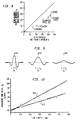
circuitry 16 shown in FIG. 1; - FIG. 8 is a graph showing the relationship between the values of Young's Modulus measured by the National Bureau of Standards and those determined using the apparatus of the present invention for various metal test bars;
- FIG. 9 shows illustrations of the effect of dispersion on stress wave propagation; and
- FIG. 10 is a graphical illustration of the relationship between tube length and dispersive time delay.
- To facilitate understanding, identical reference numerals have been used to denote identical elements common to the figures.
- FIG. 1 shows, in pictorial form, a preferred embodiment of an apparatus used in determining Young's Modulus of a tube in accordance with the present invention. The tube can be of various lengths and diameter. If discontinuities, such as kinks, nicks, or deep scratches, are present in the tube, it is believed that these discontinuities lead to longer transit times for the stress waves which will lower the value of Young's Modulus. In
apparatus 10, instrumentedhammer 12 hasaccelerometer 14 affixed to the head of the hammer.Accelerometer 14 is connected vialead 15 tocircuitry 16 whose function will be described in detailed below.Striking cap 18 is affixed to one end oftube 20.Cap 22 is affixed to the other end.Accelerometer 24 is affixed to cap 22 and is connected tocircuitry 16 vialead 26. - When the head of
hammer 12 strikes cap 18, stress waves 30 as shown in FIG. 2, including both P-waves and S-waves, are generated therein andaccelerometer 14 generates an electrical pulse which is detected bycircuitry 16 which then begins a timing function. As is known in the art, in general when an axial shock stress is placed on an elastic body, longitudinal waves (also known as compressional or dilatational waves) and shear waves are generated, both of which types of waves propagate in the body. Typically, the longitudinal waves are referred to as P-waves and the shear waves are referred to as S-waves. The velocity of propagation of P-waves in the elastic body is faster than that of S-waves. For tubes, however, the amplitudes of the S-waves are greater than those of the P-waves. Although embodiments of the present invention detect either P-waves or S-waves, to assure maximum accuracy of the resulting measurements, the measurement of P-waves is preferred. The increased accuracy results because the detected wave front is relatively sharp since it only contains energy from one type of wave, namely, P-waves. In contrast, if one were to detect S-waves, the detected wave front would not be as sharp because, in general, it would contain some residual energy from the P-waves along with energy from the S-waves. This would therefore limit the repeatability of the resulting measurements. - Furthermore, as shown in FIG. 2, the propagation of stress waves, i.e., both P- and S-waves, through the
cap 18 into thetube 20 is complex. However cap 18 helps to ensure that the stress waves, including P-waves 30enter tube 20 in a relatively uniform manner and propagate therein along the direction shown byarrows 32.Cap 18 serves the purposes of (1) helping to provide a uniform wave front at one end oftube 20 and (2) making it easier for an operator to strike the end oftube 20, i.e., withoutcap 18, an operator would have to strike the narrow edge of the tube. Further, any delay in transit time of P-waves 30 which results from the use ofcap 18 andcap 22 is repeatable and can be measured in a calibration procedure and subtracted out from the total transit time measurement made by the inventive P-wave tester. - As shown in FIG. 2, when the wave front representing P-
waves 30 reaches end 34 oftube 20, this wave front causes P-waves to be generated in and then propagate downtube 20 towardcap 22. As shown in both FIGS. 1 and 2,accelerometer 24 detects P-waves 30 and, in response, applies an electrical pulse on lead 26 (see FIG. 1) which is connected tocircuitry 16 which then stops its timing function. The electrical pulse generated byaccelerometer 24 is delayed in time from the electrical pulse generated byaccelerometer 14 by an amount which represents the transit time for P-waves 30 to propagate throughcap 18,tube 20 andcap 22.Circuitry 16 utilizes this time delay, after correction for the delays caused bycaps accelerometer 24 to determine a corrected transit time for P-waves 30 to propagate from one end oftube 20 to the other. - Now, once the transit time is known, Young's Modulus, E, is then determined in accordance with the following equation:

where: ν is Poisson's ratio, L is the length oftube 20, ρ is the density oftube 20 and T is the transit time of the wave front of the P-waves from one end oftube 20 to the other. In accordance with the present invention, ν, L and ρ are determined as follows: (1) Poisson's ratio ν is essentially constant for the type of materials used to form flow conduits of a Coriolis mass flow rate meter; (2) length L oftube 20 may be measured to suitable accuracy in an industrial environment with a tape measure; and (3) density ρ oftube 20 can be measured to suitable accuracy in an industrial environment in accordance with the following formula for a tube having a circular cross section:

where: w is the weight, g is the gravitational constant and V is the volume of the tube. The volume, V, is calculated by multiplying the area, A, of a cross section oftube 20 by its length L. The area is calculated from the following:

where: do is the outer diameter oftube 20 and di is the inner diameter oftube 20. - In one embodiment of the
present invention circuitry 16 further includes: (1) circuitry through which an operator can supply initial data values such as numerical values of Poisson's ratio and the length and density oftube 20 and a calibration factor for the particular tube material that is used for correcting the transit time, and (2) circuitry that measures the transit time of P-waves propagating intube 20 and computes Young's Modulus from the initial data and the measured transit time. - Specifically,
hammer 12, shown in FIG. 1, is an instrumented hammer that includesaccelerometer 14 and is used to excitecap 18 with a nearly constant force over a broad frequency range, the frequency range being determined by the particular hammer structure chosen. Such instrumented hammers having an accelerometer affixed to the head thereof are available from PCB Piezotronics, Inc., 3425 Walden Avenue, Depew, New York 14043. Further,accelerometer 24, which is affixed to cap 22 for detecting P-waves generated intube 20, may also be obtained from PCB Piezotronics, Inc. Note, as will be described in detail below,cap 22 is in intimate contact withtube 20. - As has been discussed above, inasmuch as the inventive method and apparatus measures the transit time of P-waves in
tube 20 and does not require the tube to be clamped to a base, the orientation of the inventive apparatus is not critical. Furthermore, the transit time of the P-waves intube 20 can be measured while the tube is being supported on almost any surface. The only exception being that the tube should not be supported on a surface in which stress waves induced therein by the inventive apparatus travel faster on the surface than P-waves travel through the tube. Thus, for example, since stress waves travel faster in aluminum than in steel, placing a steel tube directly on an aluminum table for measurement could result inaccelerometer 24 detecting stress waves traveling through the aluminum table before detecting P-waves traveling through the steel tube. Nevertheless, even this problem can be eliminated if the steel tube is supported by foam or rubber pads. The foam or rubber pads act to substantially prevent stress waves from being induced in the aluminum table. - The efficacy of the inventive method and apparatus in an industrial environment is such that we can achieve at least 1 percent accuracy in the measurement of Young's Modulus even when the length of
tube 20 is determined with a tape measure. Thus, whentube 20 is 20 feet (approximately 6.1 meters) long, its length need only be determined to within a tolerance of ± 1/4 inch (approximately .6 centimeters) for a 0.2 percent accuracy in Young's Modulus, whereas, whentube 20 is 2 feet (approximately 61 centimeters) long, its length need only be determined to within a tolerance of ± 1/32 inch (approximately .08 centimeters) for a 0.3 percent accuracy in Young's Modulus. This tolerance is determined by expanding Eq. (1) in a Taylor series about the correct length and ascertaining the error induced in Young's Modulus by a particular error in the length oftube 20. Specifically, the fractional measurement error in Young's Modulus is approximately twice the fractional measurement error in length. - FIG. 3 shows, in pictorial form,
cap 18 for the embodiment shown in FIG. 1. In FIG. 3,cap 18 comprises cap fitting 100 having ahole 102 drilled in the side thereof.Hole 102 is threaded to permit setscrew 104 to be threadably engaged therein. In use, cap fitting 100 is placed over the end oftube 20 so that the end oftube 20 abutsinternal face 106. Setscrew 104 is then tightened against the side oftube 20 to ensure intimate contact between cap fitting 100 and the end oftube 20. The cap shown in FIG. 3 may also be used to holdaccelerometer 24 by drilling and tapping a hole intowall 108 thereof and affixingaccelerometer 14 thereto with a threaded stud. - FIG. 4 shows, in pictorial form, an alternative embodiment of
cap 22 used for affixingaccelerometer 24 totube 20.Fixture 120 is a compressive fitting comprising clampingnut 122, first ferrule orsleeve 124, second ferrule orsleeve 125 andmetal seating nut 126. First clampingnut 122 is slipped ontube 20 followed bysleeves nut 122 ontube 20. Next,metal seating nut 126 is slipped ontotube 20 until the end oftube 20strikes seat 127 provided inmetal seating nut 126. Clampingnut 122 has threads on the inside thereof which are threadably connected with threads on the exterior ofmetal seating nut 126. Whenmetal seating nut 126 is threaded into clampingnut 122,first sleeve 124 andsecond sleeve 125 are deformed by forces created by the threading together of clampingnut 122 andmetal seating nut 126. This ensures good metal-to-metal contact betweentube 20 andseating nut 126.End wall 128 ofmetal seating nut 126 is drilled and tapped and threadedstud 130 is inserted therein.Accelerometer 24 is threaded ontostud 130. In one embodiment, clampingnut 122,sleeve 124 andmetal seating nut 126 are formed from SWAGELOK tube fittings in whichmetal seating nut 126 is modified to threadably accept threaded stud 130 (SWAGELOK is a registered trademark of Crawford Fitting Company of Solon, Ohio). For example for 5/8 inch diameter tubing a SWAGELOK fitting having catalog no. 5/8-1010-C is used. For tubing of other diameters, an appropriately sized fitting would be selected. SWAGELOK fittings are available from Crawford Fitting Company, 29500 Solon Road, Solon, Ohio 44139. In use, after Young's Modulus is determined in accordance with the present invention,metal seating nut 126 andaccelerometer 24 are removed fromtube 20 and clampingnut 122 andsleeves Tube 20 is later cut to remove clampingnut 122 anddeformed sleeves nut 122 anddeformed sleeves tube 20 has had its Young's Modulus determined. - FIG. 5 shows, in pictorial form,
fixture 140 for use in formingstriking cap 18 forhammer 12 and/or a fixture foraccelerometer 24, both shown in FIG. 1. In FIG. 5,fixture 140 comprisesclamp 142 loaded withspring 144 and havingjaws tube 20.Jaws jaws tube 20 and also damps out stress waves propagating through thefixture 140 intotube 20. Extending fromjaws tube 20, are threemetal tie rods Tie rods connect clamp 142 tometal plate 156 so thatplate 156 is positioned substantially parallel to the end oftube 20. As shown in FIG. 5,plate 156 andjaws holes 158 disposed therein so thattie rods - In one embodiment, both ends of
tie rods holes 158 inplate 156. As shown in FIG. 5, compression springs 162, 164 and 166 are disposed between the end oftie rods holes 158 injaws nuts 160 threaded on the end of therods -
Plate 156 can also be provided withprojection 170 oncontact surface 171 thereof.Projection 170 may be bullet or cone shaped and is used for guiding an end oftube 20 into intimate contact with pins oncontact surface 171 offixture 140. Preferably, at least three equally spaced, radially extending raised portions, such as metal pins 172, are provided on thecontact surface 171. Three pins are shown in FIG. 5.Pins 172 are fixed by conventional fastening means such as glue, welding or brazing.Pins 172 serve as intimate contact points between the end oftube 20 andfixture 150 and allow for any unevenness that can occur at the tube end. Grooves may also be provided incontact surface 171 for receivingpins 172. Alternatively, rounded ridges incontact surface 171 could also be substituted forpins 172. - In operation,
jaws clamp 142 are opened.Fixture 140 is then slid over and down tube 20 a distance which is sufficient to compress compression springs 162, 164 and 166 to supply a longitudinal force which holdsplate 156 and pins 172 in intimate contact with the end oftube 20. Iffixture 140 is used to holdaccelerometer 24, a hole for a threaded stud may be drilled and tapped inplate 156 as is done forstud 130 for the embodiment shown in FIG. 4. - FIGS. 6A, 6B and 6C show in cross-section various embodiments for the connection between
plate 156 and the tie rods,illustratively tie rod 154, taken along line VI-VI of FIG. 5 forfixture 140 shown in FIG. 5. In FIG. 6A, the diameter ofportion 180 oftie rod 154 is reduced in comparison to the diameter of throughhole 158 inplate 156. The ends oftie rods hole 158 is sufficiently greater than the diameter oftie rod 154, which is not reduced in diameter, to allow a loose fit. As shown by the various dashed lined positions of alignment, 186 and 188, ofplate 156 in FIG. 6B, this allows some degree of freedom of motion or wobble betweentie rod 154 andplate 156. Also, this in turn allowsplate 156 to be in intimate contact with the end oftube 20 even though the end oftube 20 is not cut perpendicular to its axial extent. In FIG. 6C, throughhole 158 is chamfered.Chamfers plate 156 with respect totie rod 154. In a further embodiment, the ends oftie rods plate 156 form ball and socket joints (not shown). Such a ball and socket joint allows relative movement between the tie rods andplate 156 to accommodate misalignment of the end oftube 20 from perpendicularity. An additional advantage of the loose fit in each of these embodiments is that the amount of force required to open the jaws ofclamp 142 is reduced. When theclamp 142 is opened, the tie rods, which are typically made of steel and are somewhat stiff, will bend outward away from the tube. The angular rotation of the tie rods reduces the amount of bending that must be done by the tie rods when theclamp 142 is opened which in turn reduces the amount of opening force required. Note that whenfixture 140 is used as a striking cap, intimate contact with the end oftube 20 is assured at the time the fixture is first struck byhammer 12. Oncehammer 12hits plate 156,plate 156 may rebound from the end oftube 20 and evenre-strike tube 20. However, by the time such an event has occurred, the initial P-waves have already propagated to the other end oftube 20 and have been detected. - FIG. 7 is a block diagram of
circuitry 16 shown in FIG. 1. Whenhammer 12 strikes cap 18 (see FIG. 1),accelerometer 14 affixed to hammer 12 generateselectrical pulse 200 onlead 15 as shown in FIG. 7. At the same time, P-waves are generated intube 20. The P-waves travel toward cap 22 (see FIG. 1) andaccelerometer 24. Upon detecting P-waves,accelerometer 24 generateselectrical pulse 300 onlead 26 as shown in FIG. 7.Electrical pulses amplifiers amplifiers amplifiers Amplifiers pulses accelerometers respective voltage sources circuitry 16 is not triggered by noise. - The output from
amplifier 202 is applied as input to D type flip-flop 204 and causes output Q to which lead 205 is connected to go "high."Lead 205 is connected to the START input ofcounter 400. When output lead 205 goes "high," counter 400 starts counting. Thus, whenhammer 12 strikes cap 18 and launches P-waves intotube 20, counter 400 starts counting. The time base and hence the resolution ofcounter 400 is determined bycrystal 401 which typically has a frequency of 10 MHz. - As discussed above, when
accelerometer 24 detects P-waves at the end oftube 20, this accelerometer generatespulse 300 which, in turn, produces an output fromamplifier 302 which is applied as input to D type flip-flop 304. This causes output Q of this flip-flop which is connected to lead 305 to go "high."Output lead 305 is connected to the STOP input ofcounter 400. When output lead 305 goes "high,"counter 400 stops counting and sends its count toLED display 410. This count represents the transit time of P-waves propagating throughcaps tube 20. After counter 400 outputs its count toLED display 410, this counter is inhibited from further counting for a short period which is sufficiently long to allow any ringing intube 20 to decay. - Young's Modulus, E, using the corrected transit time is then determined by using Eq. (1). In one embodiment, Eq. (1) can be evaluated by using a programmable calculator and Young's Modulus is determined. In further embodiments of the present invention, Eq. (1) can be evaluated in a processor such as microprocessor. In FIG. 7,
microprocessor 425 is provided with the count fromcounter 400 overlead 415 and with the numerical value of Poisson's ratio ν and the length L, density ρ of the tube and the calibration factors via an entry device such askeyboard entry device 430. After performing the calculation,microprocessor 425 transmits the result for display to displaydevice 435. The method by which processors such asmicroprocessor 425 may be interfaced with entry devices such as a keyboard entry device and may be programmed to perform the calculation of Eq. (1) are well known in the art. - In FIG. 7, whenever a pulse is applied as input to flip-flop 204 from
amplifier 202 in response to hammer 12striking tube 20, flip-flop 204 applies at its Q not output an appropriate level over lead 358 to reset one-shot 350. In response thereto, one-shot 350 generates an output after a delay of, for example, 1.5 seconds. This output is applied overleads flops 204 and 304, respectively, to reset them and overlead 357 as an input to ORgate 351. The output of ORgate 351 is applied as input to initialization input INIT ofcounter 400. As a result,circuitry 16 is reset and ready for the next measurement. The delay is chosen to be sufficiently long so that any ringing in the tube will have dissipated. Further, the delay should be sufficiently long thatcounter 400 is not reset by one-shot 350 before the P-waves generated byhammer 10 are detected byaccelerometer 24. This last requirement does not present any practical problem because the P-waves have a transit time which is measured in microseconds whereas the period of one-shot 350 is, for example, 1.5 seconds. - As shown in FIG. 7,
counter 400 may also be initialized by manually closingswitch 360 which is connected between anappropriate voltage source 361 and an input to ORgate 351. - To determine the accuracy of the present method and apparatus, five certified test bars were obtained from the National Bureau of Standards. The bars were solid and made from aluminum, titanium, stainless steel alloy 321 (SS321), ferrous steel and inconel. The NBS certified mechanical properties of these 5 bars is given in Table 1 rows 1 through 4.

Using Eq. (4) below and the values for v₁ and L given in Table 1 above, the NBS transit time To for each of the test bars can be determined.

The results for To are given in row 6 of Table 1. The five test bars were then tested using the circuitry of Figure 7 and a modified test setup.Accelerometer 24 was mounted directly on the end of the bar using a short mounting stud vice forfixture 120. The instrumentedhammer 12 impacted directly on the other end of the bar. Each bar was struck at least 10 times and the transit time, T, was measured viacircuitry 16. The measured transit times, T, were consistently higher than the NBS transit time To. For each test, the measured Young's Modulus, was determined using Eq. (1) and then a mean value, Em, was determined. In FIG. 8 the results of comparing the measured mean value of Young's Modulus, Em, to the NBS value, E, is shown. The dashed line represents the ideal 1:1 relationship between the measured and NBS values for Young's Modulus. For Young's Modulus as determined using the measured transit times, these times T were consistently lower than the NBS values. The difference ΔT₁ between the measured transit time T and the NBS transit time To was determined for each test. The values for ΔT₁ for each test bar were averaged to provide a mean ΔT1. This mean ΔT₁ is dependent on the material and can be thought of as a tare value or offset introduced by instrumentedhammer 12,accelerometers circuitry 16. To determine the effect offixture 140 andfixture 120 on the measured transit time T, the tests were repeated for each test bar. First,fixture 120 was installed and the tests were run. Bothfixtures fixture 120 is designated ΔT₂ and that offixture 140 is designated ΔT₃. The sum of delays ΔT₁, ΔT₂, and ΔT₃ represents the total tare or offset and is used as a calibration factor ΔT as shown in Eq. (5).

where: - To =
- NBS Transit Time in microseconds
- TT =
- Total Measured Transit Time including delays
- Once the value of Young's modulus for the tube has been determined, the tubes for use in a multiple tube Coriolis mass flow rate meter can be selected. Based on known methods of statistical process control, we believe that a ± 4 percent variation in the Young's Modulus of the tubes to be used in a Coriolis meter is an acceptable upper bound and that this will help to alleviate the zero-level offset problem previously described. At first, this variation seems to be greater than that given for the axial tensile test previously described. However, applying the same methods of statistical process control to the ± 3 percent variation in the axial tensile test would result in a ± 12 percent variation in order to have the same degree of confidence in the axial tensile test as in the test given by the inventive method and device. This ±12 percent variation is in excess of the ± 11 percent variation known to cause difficulties.
- An additional correction factor that is dependent on the length L of the tube need also be considered when the tube length is significantly longer than the length of the test bars that are used to develop the calibration factor. Here the NBS test bars were each approximately one meter in length. This correction factor accounts for the dispersion of the stress wave as it travels down the length of the tube. As the stress wave propagates down the tube, it spreads out or disperses. The longer the tube, the more the waveform spreads out. FIG. 9 illustrates the effect of dispersion on a stress wave front as it propagates down the tube at increasing periods of t₁, t₂ and t₃ of transit time. The arrow in each of waveforms (a), (b) and (c) in this figure indicates the direction of wave propagation. It can be seen that the wave front becomes less and less steep as transit time increases. Because
circuitry 16 uses a fixed non-zero threshold level to detect the wave front, as the slope of the wave front flattens, it takes longer to reach this threshold, and, hence, an additional time delay is introduced. This dispersive time delay is designated T₄. It should be realized that as the length of the tube to be tested approaches the length of the test bar that was used to develop the calibration factor ΔT, dispersion time delay T₄ will decrease toward zero. This occurs because the dispersive time delay is inherently included in the calibration factor because it is impossible to have test bar that has a length of zero. Where the tube to be tested is shorter than the test bar used to develop the calibration factor, the dispersive time delay will have a negative value. - The effect of dispersion of the stress wave on Young's Modulus is to decrease the value thereof for longer tubes. This is shown in Tables 3 and 5. The data in Table 3 was collected by measuring the total transit time, TT, using the inventive device, for a 316L stainless steel tube approximately 5.5 meters in length (Tube no. 11). A one meter section was then removed from the tube and the total transit time was again measured for the shortened tube (Tube no.10). This procedure of cutting and measuring transit times was repeated until 5 tubes each of approximately one meter in length were cut from the original tube. The tube lengths, L, are given at
Column 2 of Table 3. The total transit times for these 5 one meter tubes were then measured (Tube no. 1 - 5). The total transit time (column 3 of Table 3) for each of the tubes was then corrected using the calibration factor ΔT (column 4 of Table 3) as previously described and Young's Modulus, E, values were determined and are given at Column 5 of Table 3. For the 5 one meter tubes, the mean value for Young's Modulus was 184.8 GPa with a standard deviation of 0.8 percent of the mean. As the length of tube increases, the calculated value for the Young's Modulus drops off for the longest tube to 151.3 GPa, or a drop of 18 percent.
- The data in Table 3 indicates that Young's Modulus is essentially constant for the five one meter tubes. With Poisson's Ratio and the density assumed to be constant for the tube, the speed of propagation, v₁, can be calculated by:

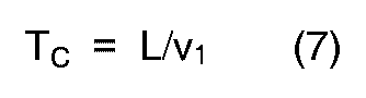
Table 4 atcolumn 2 shows the speed of propagation, v₁, for the five one meter tubes (Tube no. 1 - 5). For these five tubes, the mean v₁ is 0.5590 cm/µsec with a standard deviation of 0.0024 cm/msec. This mean value was then assumed to be constant for the other tubes (Tube no. 6 - 11) and was used to find a corrected transit time TC without dispersion as follows:
This data is shown in Table 4 at column 3. The dispersive time delay T₄ is defined:

Column 4 of Table 4 shows that dispersive time delay T₄ is approximately zero for the five one meter tubes (Tube no. 1 - 5) and increases uniformly for the longer tubes. This dependence of the dispersive time delay, T₄, on length, L, is shown in FIG. 10 atcurve 500 and is linear over the range tested. A regression analysis on the length and dispersive time delay data yields:

with the coefficients α₁ and α₀ being:
α₁ = 0.2225 µsec/cm
α₀ = - 20.6 µsec
The coefficient of determination for this formula is 0.9997. Eq. (9) for a 316L stainless steel tube is graphically represented in FIG. 10 atcurve 500.
Substituting Eq. (9) in Eq. (8) and solving for TC yields:

Column 5 presents the data, designated TC′ developed when TC is calculated using Eq. (10) and the values for tube length, TT, and ΔT for each of the tubes listed in Table 3. As can be seen there is close agreement between the values of TC and TC′. Column 6 of Table 4 presents the Young's Modulus corrected for all propagation delays including dispersion and is designated EC. As can be seen there is very little variation in the values for EC even though the tube length goes from approximately 1 meter to about 5.5 meters. For tube lengths in excess of one meter, the previously described procedure for arriving at a corrected transit time can be modified by determining the dispersive time delay T₄ using Eq. (9) then subtracting both dispersive time delay T₄ and calibration factor ΔT from the measured transit time to find the corrected transit time which would then be used in Eq. (1) to solve for Young's Modulus. Again this procedure can be implemented using a programmable calculator or a microprocessor. The coefficients α₁ and α₀ can be stored in a look up table. - It was thought that coefficients α₁ and α₀ would not change significantly were another tube material used. Surprisingly, we have discovered that this was not the case. A tube fabricated from HASTELLOY Alloy C-276 alloy (HASTELLOY is a trademark of Cabot Co. of Kokomo, Indiana and HASTELLOY Alloy C-276 alloy is a designation of the Cabot Co.) was tested using a procedure similar to that described for the 316L stainless steel tube. This data is given in Tables 5 and 6.


Again the cut and measure technique used for the 316L stainless steel tube was used for the Hastelloy Alloy C-276 tube. Here however four tubes of approximately one meter in length were cut from the original tube. The mean value for v₁ was determined using the values for Tubes No. 2 - 4. This mean value was then used with Tube No. 1 and Tubes No. 5 - 9 to determine the corrected transit time TC given at Column 3 of Table 6. The dispersive time delay values were calculated as previously set forth and are shown at Column 4 of Table 6. Column 5 presents the data, designated TC'′ developed when TC is calculated using Eq. (10) and the values for tube length, TT, and ΔT for each of the tubes listed in Table 5. As can be seen there is close agreement between the values of TC and TC'. Column 6 of Table 6 presents the Young's Modulus corrected for all propagation delays including dispersion and is designated EC. As can be seen there is very little variation in the values for EC even though the tube length goes from approximately 1 meter to about 5.5 meters. - Using regression analysis techniques with the length L of Table 5 and the dispersive time delay T₄ given in Table 6 the coefficients α₁ and α₀ in Eq. (9) were found to be:
α₁ = 0.1221 µsec/cm
α₀ = - 13.9 µsec
The coefficient of determination for this formula was 0.9973. The values listed for Tube No. 1 were not used to determine the coefficients. Again this relationship is graphically illustrated in FIG. 10 atcurve 510. A comparison of the slopes ofcurve - To account for the dispersive time delay, the previously described procedure for arriving at a corrected transit time is modified. The dispersive time delay T₄ is determined using Eq. (9). The dispersive time delay T₄ and the calibration factor ΔT are subtracted from the measured transit time to find the corrected transit time which would then be used in Eq. (1) to solve for Young's Modulus. This is the preferred method. This procedure can be implemented using a programmable calculator or a microprocessor. Again these coefficient values could be stored in a look up table and be selected when the material corresponding to this particular set of coefficients was to be tested. A table of coefficients for other tube materials can be determined using the approach set forth hereinabove.
- Although the apparatus and method described are for measuring P-waves, these can also be used to measure S-waves. Because S-waves move along the tube in a direction perpendicular to the longitudinal axis of the tube,
accelerometer 24 would be located near the end of the tube on the tube wall, i.e., in a location that would be substantially perpendicular to the longitudinal axis of the tube. The tube is still struck on the opposite end or on the tube wall at the opposite end. If S-wave transit times are measured, then Poisson's ratio n can be determined using standard formulas. In addition, measuring S-wave transit times provides a second way to determine Young's Modulus.Circuitry 16 would be modified to suppress detection of the P-waves, which are the first set of stress waves to propagate down the tube, such as by using a time delay and then detecting the S-waves which are the next set of propagating waves. Typically in tubes, S-waves have a significantly greater amplitude than P-waves. Accordingly, a threshold discriminator set for the higher amplitude S-waves can also be used in the modified circuitry to detect and measure the transit time of the S-waves in lieu of or in combination with the previously mentioned threshold discriminator.

Calibration factors can be developed for a particular material that is to be tested. However, for industrial purposes it is believed that accurate results will be obtained by selecting a calibration factor ΔT for a material in the table that most closely matches the material to be tested. The calibration factor ΔT is subtracted from the measured transit time. The corrected transit time is then used in Eq. (1) to solve for Young's Modulus. This procedure can be performed by the programmable calculator or by providing the
Claims (3)
- A method of manufacturing a Coriolis mass flow rate meter having at least two flow tubes and a reduced zero level offset, said method comprising the steps of:
testing each one of a plurality of tubular specimens (20) fabricated of substantially the same material in order to determine a value of Young's modulus (E) to a pre-defined accuracy and associated with said one specimen; wherein said testing step comprises the steps of:
exciting P-waves (30) at a first end (18) of said one specimen (20);
measuring a value of transit time (TT) for the P-waves (30) to propagate from said first end (18) through said one specimen (20) to a second end (22) thereof;
measuring values of length (L) and density (ρ) of said one specimen (20), the method further comprising
determining a value of a pre-defined calibration factor (ΔT) for compensating for transit delay introduced into said measured transit time (TT) by a test fixture (120, 140) used in said measuring step and a value of a dispersive time delay factor (T₄) for compensating for transit time delay caused by P-wave dispersion as said P-wave (30) propagates along said one specimen (30), wherein said dispersive time delay factor varies in response to the length (L) of said one specimen (20);
subtracting both the values of the dispersive time delay factor (TA) and the pre-defined calibration factor (ΔT) from the measured transit time value (TT) to form a corrected transit time value (TC) for said one specimen (20); and
generating said associated value of Young's modulus (E) from the length value (L), the density value (ρ) and corrected transit time value (TC) for said one specimen (20); and
selecting specific ones of said tubular specimens (20) for incorporation as corresponding flow tubes within said Coriolis mass flow rate meter wherein all of said specific ones of said tubular specimens possess associated values of Young's modulus (E) that exist within a pre-defined range so as to advantageously reduce zero level offset inherent in said meter. - The method according to claim 1, characterized in that the Young's modulus (E) generating step comprises the step of determining said associated value of Young's modulus (E) for said one specimen in accordance with the following equation:

where: ν is Poisson's ratio of the material of which said one specimen is fabricated,
L is the measured length value of said one specimen,
ρ is the measured density value of said one specimen,
and
TC is the corrected transit time value for said one specimen. - The method according to claims 1-2, characterized in that said pre-defined calibration factor value (ΔT) and dispersive time delay factor value (T₄) determining step comprises the step of determining a value for the time delay factor (T₄) for said one specimen in accordance with the following equation:

where: α₁ and α₀ are predetermined coefficients.
Applications Claiming Priority (2)
| Application Number | Priority Date | Filing Date | Title |
|---|---|---|---|
| US07/093,424 US4845989A (en) | 1987-09-04 | 1987-09-04 | Method and apparatus for determining elastic constants in tubes |
| US93424 | 1987-09-04 |
Publications (3)
| Publication Number | Publication Date |
|---|---|
| EP0306110A2 EP0306110A2 (en) | 1989-03-08 |
| EP0306110A3 EP0306110A3 (en) | 1990-06-13 |
| EP0306110B1 true EP0306110B1 (en) | 1994-04-06 |
Family
ID=22238866
Family Applications (1)
| Application Number | Title | Priority Date | Filing Date |
|---|---|---|---|
| EP88201881A Expired - Lifetime EP0306110B1 (en) | 1987-09-04 | 1988-09-02 | Method for manufacture of a coriolis flow meter |
Country Status (4)
| Country | Link |
|---|---|
| US (1) | US4845989A (en) |
| EP (1) | EP0306110B1 (en) |
| JP (1) | JPH01158346A (en) |
| DE (1) | DE3888899T2 (en) |
Families Citing this family (28)
| Publication number | Priority date | Publication date | Assignee | Title |
|---|---|---|---|---|
| JPH01296112A (en) * | 1988-05-24 | 1989-11-29 | Oval Eng Co Ltd | Coriolis mass flowmeter |
| DE3923409A1 (en) * | 1989-07-14 | 1991-01-24 | Danfoss As | MASS FLOW MEASURING DEVICE WORKING ACCORDING TO THE CORIOLIS PRINCIPLE |
| DE3930424A1 (en) * | 1989-09-12 | 1991-03-21 | Tabac Fab Reunies Sa | METHOD FOR CHECKING THE EXISTENCE OF A PIPELINE CONNECTION BETWEEN TWO END POINTS |
| US5073208A (en) * | 1989-09-14 | 1991-12-17 | K-Flow Corporation | Method for cryogenic treatment of Coriolis mass flow meter structures |
| JPH0464035A (en) * | 1990-07-03 | 1992-02-28 | Matsushita Electric Ind Co Ltd | Evaluating method of strength of magnetic recording medium |
| DE4200871C1 (en) * | 1992-01-15 | 1993-05-06 | Wolfgang 8045 Ismaning De Drahm | Determn. of mechanical stress conditions of measuring tubes of flow meter |
| DE4224379C2 (en) * | 1992-07-06 | 1998-05-20 | Krohne Messtechnik Kg | Mass flow meter |
| US5535627A (en) * | 1994-01-14 | 1996-07-16 | The Board Of Regents Of Oklahoma State University | Roll structure acoustic gage and method |
| DE4441225C2 (en) * | 1994-11-19 | 1996-09-12 | Danfoss As | Mass flow meter |
| JPH10512774A (en) * | 1995-01-25 | 1998-12-08 | シユトウツシ,エドガール | Method and apparatus for determining propagation characteristics of a mechanical wave in a three-dimensional structure |
| US6748813B1 (en) | 1998-12-08 | 2004-06-15 | Emerson Electric Company | Coriolis mass flow controller |
| US6513392B1 (en) * | 1998-12-08 | 2003-02-04 | Emerson Electric Co. | Coriolis mass flow controller |
| US6920790B2 (en) * | 2000-06-22 | 2005-07-26 | The Boeing Company | Apparatus for in-situ nondestructive measurement of Young's modulus of plate structures |
| US6575036B1 (en) | 2000-06-22 | 2003-06-10 | The Boeing Company | Method for in-situ nondestructive measurement of Young's modulus of plate structures |
| US6609428B2 (en) * | 2001-01-19 | 2003-08-26 | The United States Of America As Represented By The Secretary Of The Navy | Nonresonant technique for estimation of the mechanical properties of viscoelastic materials |
| JP4636747B2 (en) * | 2001-08-22 | 2011-02-23 | 湖北ベニヤ株式会社 | Equipment for measuring Young's modulus of wood such as veneer veneer |
| US6658914B2 (en) | 2002-03-04 | 2003-12-09 | Presstek, Inc. | Method and apparatus for characterizing roll structure |
| US6997032B2 (en) * | 2003-04-08 | 2006-02-14 | Invensys Systems, Inc. | Flowmeter zeroing techniques |
| DE10356383B4 (en) * | 2003-12-03 | 2007-06-21 | Abb Patent Gmbh | Mass flow meter |
| DE102004018683B3 (en) * | 2004-04-17 | 2005-09-08 | Daimlerchrysler Ag | Method for quality control of a work piece especially the seating between two components using a measure of vibration as an indication of quality |
| US7340958B2 (en) * | 2005-06-28 | 2008-03-11 | Weyerhaeuser Company | Methods for determining potential characteristics of a specimen based on stress wave velocity measurements |
| DE102005044008B4 (en) * | 2005-09-14 | 2007-07-12 | Krohne Ag | Method for testing a mass flowmeter |
| JP4696243B2 (en) * | 2006-03-03 | 2011-06-08 | 国立大学法人名古屋大学 | Young's modulus estimation method, Young's modulus estimation program, and Young's modulus estimation apparatus |
| CN101622519A (en) * | 2007-02-22 | 2010-01-06 | 微动公司 | Vibrating conduit diagnostic systems and methods |
| JP5558161B2 (en) | 2010-03-29 | 2014-07-23 | アロン化成株式会社 | Thermally conductive elastomer composition used as a spacer between a heating element and a cooling component |
| CN107091878B (en) * | 2017-04-27 | 2020-08-07 | 中国地质大学(武汉) | Young modulus measuring instrument based on transient excitation |
| CN110470537A (en) * | 2019-08-21 | 2019-11-19 | 肖印刚 | A kind of PE feedwater piping intends true experiment device |
| CN119510579A (en) * | 2024-10-31 | 2025-02-25 | 武汉船用电力推进装置研究所(中国船舶集团有限公司第七一二研究所) | A method and device for measuring the Young's modulus of a motor stator core structure on site |
Family Cites Families (13)
| Publication number | Priority date | Publication date | Assignee | Title |
|---|---|---|---|---|
| CA918286A (en) * | 1968-09-13 | 1973-01-02 | Washington State University Research Foundation | Non-destructive method of grading wood materials |
| US3720098A (en) * | 1971-03-22 | 1973-03-13 | Atomic Energy Commission | Ultrasonic apparatus and method for nondestructively measuring the physical properties of a sample |
| US3896662A (en) * | 1973-12-27 | 1975-07-29 | Us Army | Ultrasonic measuring device |
| FR2309851A1 (en) * | 1975-05-02 | 1976-11-26 | Gueugnon Forges | METHOD AND APPARATUS FOR MEASURING STRAIN IN A BAND SUBJECT TO TENSION AND THEIR APPLICATIONS, IN PARTICULAR FOR MEASURING THE STATE OF FLATNESS OF SUCH BAND |
| JPS5827449B2 (en) * | 1978-08-09 | 1983-06-09 | 富士電機株式会社 | Ultrasonic propagation time detection circuit device |
| US4353256A (en) * | 1981-01-19 | 1982-10-12 | The Electricity Council | Non-contact measurement of physical properties of continuously moving metal strip |
| JPS57137818A (en) * | 1981-02-19 | 1982-08-25 | Tokyo Keiki Co Ltd | Straight tube type mass flowmeter |
| JPS58151518A (en) * | 1982-03-04 | 1983-09-08 | Yokogawa Hokushin Electric Corp | Mass flow meter |
| JPS58156813A (en) * | 1982-03-15 | 1983-09-17 | Yokogawa Hokushin Electric Corp | Mass flowmeter |
| US4491025A (en) * | 1982-11-03 | 1985-01-01 | Micro Motion, Inc. | Parallel path Coriolis mass flow rate meter |
| US4574615A (en) * | 1983-12-19 | 1986-03-11 | The Babcock & Wilcox Company | Sonic apparatus and method for detecting the presence of a gaseous substance in a closed space |
| US4738143A (en) * | 1985-08-29 | 1988-04-19 | Micro Motion, Incorporated | High temperature Coriolis mass flow rate meter |
| US4674332A (en) * | 1986-02-20 | 1987-06-23 | Union Camp Corporation | Laser induced acoustic generation for sonic modulus |
-
1987
- 1987-09-04 US US07/093,424 patent/US4845989A/en not_active Expired - Lifetime
-
1988
- 1988-09-02 JP JP63218638A patent/JPH01158346A/en active Granted
- 1988-09-02 DE DE3888899T patent/DE3888899T2/en not_active Expired - Lifetime
- 1988-09-02 EP EP88201881A patent/EP0306110B1/en not_active Expired - Lifetime
Also Published As
| Publication number | Publication date |
|---|---|
| EP0306110A3 (en) | 1990-06-13 |
| US4845989A (en) | 1989-07-11 |
| DE3888899D1 (en) | 1994-05-11 |
| JPH05660B2 (en) | 1993-01-06 |
| JPH01158346A (en) | 1989-06-21 |
| EP0306110A2 (en) | 1989-03-08 |
| DE3888899T2 (en) | 1994-07-21 |
Similar Documents
| Publication | Publication Date | Title |
|---|---|---|
| US4845989A (en) | Method and apparatus for determining elastic constants in tubes | |
| US4899588A (en) | Method and apparatus for determining elastic constants in tubes | |
| Mee | Dynamic calibration of force balances for impulse hypersonic facilities | |
| JP2009031193A (en) | Impact tensile stress measurement method | |
| Al-Mousawi et al. | The use of the split Hopkinson pressure bar techniques in high strain rate materials testing | |
| US5144838A (en) | Defect detecting method and apparatus | |
| AU670115B2 (en) | Method of noise rejection in a magnetostrictive position detector including determining a valid time range for propagation of sonic pulses over a reference distance | |
| EP0787980A2 (en) | Measuring a load on a part and monitoring the integrity of the part | |
| CA2207354C (en) | Apparatus and method for determining the dynamic indentation hardness of materials | |
| Venzi et al. | Influence of inertial load in instrumented impact tests | |
| Johnson et al. | An ultrasonic method for determining axial stress in bolts | |
| US5000030A (en) | Method and apparatus for measuring dynamic response characteristics of shock accelerometer | |
| US20070157698A1 (en) | System and method for the elastic properties measurement of materials | |
| Al-Mousawi | On experimental studies of longitudinal and flexural wave propagations: an annotated bibliography | |
| Jassby et al. | Experimental technique for measurement of stress-acoustic coefficients of Rayleigh waves: An experimental technique is described for determining the two stress-acoustic coefficients relating Rayleight-wave velocity to biaxial surface stress in elastic solids. The method is applied to two aluminum alloys | |
| US6029521A (en) | Method for measuring cover thickness of reinforcing bar in concrete by using stress wave | |
| US6286359B1 (en) | Method for testing frequency response characteristics of laser displacement/vibration meters | |
| DE10220827A1 (en) | Vibration type fluid mass flow rate transducer has a vibration exciter that also imparts a torsional vibration so that shear flow is introduced making measurements insensitive to fluid viscosity or density variations | |
| US6997887B2 (en) | Evaluation of reflected time-energy profile for determination of damping capacity | |
| US7131340B2 (en) | Device for low-vibration force measurement in rapid dynamic tensile experiments on material samples | |
| US20040249304A1 (en) | Evaluation of reflected time-energy profile for evaluation of osseointegration and density | |
| Kishi et al. | Dynamic crack growth during pop-in fracture in 7075 aluminum alloy | |
| US4862746A (en) | Vibration tester for screws | |
| EP0429446A1 (en) | Non-destructive evaluation of ropes by using transverse vibrational wave method | |
| Hamdan et al. | A crossbow system for high-strain-rate mechanical testing |
Legal Events
| Date | Code | Title | Description |
|---|---|---|---|
| PUAI | Public reference made under article 153(3) epc to a published international application that has entered the european phase |
Free format text: ORIGINAL CODE: 0009012 |
|
| AK | Designated contracting states |
Kind code of ref document: A2 Designated state(s): BE DE FR GB IT LU NL |
|
| PUAL | Search report despatched |
Free format text: ORIGINAL CODE: 0009013 |
|
| RHK1 | Main classification (correction) |
Ipc: G01F 1/84 |
|
| AK | Designated contracting states |
Kind code of ref document: A3 Designated state(s): BE DE FR GB IT LU NL |
|
| 17P | Request for examination filed |
Effective date: 19900814 |
|
| 17Q | First examination report despatched |
Effective date: 19920109 |
|
| ITTA | It: last paid annual fee | ||
| GRAA | (expected) grant |
Free format text: ORIGINAL CODE: 0009210 |
|
| AK | Designated contracting states |
Kind code of ref document: B1 Designated state(s): BE DE FR GB IT LU NL |
|
| REF | Corresponds to: |
Ref document number: 3888899 Country of ref document: DE Date of ref document: 19940511 |
|
| ITF | It: translation for a ep patent filed | ||
| ET | Fr: translation filed | ||
| PLBE | No opposition filed within time limit |
Free format text: ORIGINAL CODE: 0009261 |
|
| STAA | Information on the status of an ep patent application or granted ep patent |
Free format text: STATUS: NO OPPOSITION FILED WITHIN TIME LIMIT |
|
| 26N | No opposition filed | ||
| PGFP | Annual fee paid to national office [announced via postgrant information from national office to epo] |
Ref country code: BE Payment date: 19981016 Year of fee payment: 11 |
|
| PGFP | Annual fee paid to national office [announced via postgrant information from national office to epo] |
Ref country code: LU Payment date: 19990826 Year of fee payment: 12 |
|
| PG25 | Lapsed in a contracting state [announced via postgrant information from national office to epo] |
Ref country code: BE Free format text: LAPSE BECAUSE OF NON-PAYMENT OF DUE FEES Effective date: 19990930 |
|
| BERE | Be: lapsed |
Owner name: MICRO MOTION INC. Effective date: 19990930 |
|
| PG25 | Lapsed in a contracting state [announced via postgrant information from national office to epo] |
Ref country code: LU Free format text: LAPSE BECAUSE OF NON-PAYMENT OF DUE FEES Effective date: 20000902 |
|
| REG | Reference to a national code |
Ref country code: GB Ref legal event code: IF02 |
|
| PGFP | Annual fee paid to national office [announced via postgrant information from national office to epo] |
Ref country code: DE Payment date: 20070830 Year of fee payment: 20 |
|
| PGFP | Annual fee paid to national office [announced via postgrant information from national office to epo] |
Ref country code: GB Payment date: 20070829 Year of fee payment: 20 |
|
| PGFP | Annual fee paid to national office [announced via postgrant information from national office to epo] |
Ref country code: IT Payment date: 20070926 Year of fee payment: 20 Ref country code: NL Payment date: 20070823 Year of fee payment: 20 |
|
| PGFP | Annual fee paid to national office [announced via postgrant information from national office to epo] |
Ref country code: FR Payment date: 20070914 Year of fee payment: 20 |
|
| REG | Reference to a national code |
Ref country code: GB Ref legal event code: PE20 Expiry date: 20080901 |
|
| NLV7 | Nl: ceased due to reaching the maximum lifetime of a patent |
Effective date: 20080902 |
|
| PG25 | Lapsed in a contracting state [announced via postgrant information from national office to epo] |
Ref country code: NL Free format text: LAPSE BECAUSE OF EXPIRATION OF PROTECTION Effective date: 20080902 |
|
| PG25 | Lapsed in a contracting state [announced via postgrant information from national office to epo] |
Ref country code: GB Free format text: LAPSE BECAUSE OF EXPIRATION OF PROTECTION Effective date: 20080901 |