EP0306086B1 - Circuit arrangement for starting a high-pressure gas discharge lamp - Google Patents
Circuit arrangement for starting a high-pressure gas discharge lamp Download PDFInfo
- Publication number
- EP0306086B1 EP0306086B1 EP88201822A EP88201822A EP0306086B1 EP 0306086 B1 EP0306086 B1 EP 0306086B1 EP 88201822 A EP88201822 A EP 88201822A EP 88201822 A EP88201822 A EP 88201822A EP 0306086 B1 EP0306086 B1 EP 0306086B1
- Authority
- EP
- European Patent Office
- Prior art keywords
- duty cycle
- lamp
- ignition
- starting
- circuit arrangement
- Prior art date
- Legal status (The legal status is an assumption and is not a legal conclusion. Google has not performed a legal analysis and makes no representation as to the accuracy of the status listed.)
- Expired - Lifetime
Links
Images


Classifications
-
- H—ELECTRICITY
- H05—ELECTRIC TECHNIQUES NOT OTHERWISE PROVIDED FOR
- H05B—ELECTRIC HEATING; ELECTRIC LIGHT SOURCES NOT OTHERWISE PROVIDED FOR; CIRCUIT ARRANGEMENTS FOR ELECTRIC LIGHT SOURCES, IN GENERAL
- H05B41/00—Circuit arrangements or apparatus for igniting or operating discharge lamps
- H05B41/14—Circuit arrangements
- H05B41/26—Circuit arrangements in which the lamp is fed by power derived from dc by means of a converter, e.g. by high-voltage dc
- H05B41/28—Circuit arrangements in which the lamp is fed by power derived from dc by means of a converter, e.g. by high-voltage dc using static converters
- H05B41/288—Circuit arrangements in which the lamp is fed by power derived from dc by means of a converter, e.g. by high-voltage dc using static converters with semiconductor devices and specially adapted for lamps without preheating electrodes, e.g. for high-intensity discharge lamps, high-pressure mercury or sodium lamps or low-pressure sodium lamps
- H05B41/2881—Load circuits; Control thereof
- H05B41/2882—Load circuits; Control thereof the control resulting from an action on the static converter
- H05B41/2883—Load circuits; Control thereof the control resulting from an action on the static converter the controlled element being a DC/AC converter in the final stage, e.g. by harmonic mode starting
-
- H—ELECTRICITY
- H05—ELECTRIC TECHNIQUES NOT OTHERWISE PROVIDED FOR
- H05B—ELECTRIC HEATING; ELECTRIC LIGHT SOURCES NOT OTHERWISE PROVIDED FOR; CIRCUIT ARRANGEMENTS FOR ELECTRIC LIGHT SOURCES, IN GENERAL
- H05B41/00—Circuit arrangements or apparatus for igniting or operating discharge lamps
- H05B41/14—Circuit arrangements
- H05B41/36—Controlling
- H05B41/38—Controlling the intensity of light
- H05B41/382—Controlling the intensity of light during the transitional start-up phase
- H05B41/386—Controlling the intensity of light during the transitional start-up phase for speeding-up the lighting-up
-
- H—ELECTRICITY
- H05—ELECTRIC TECHNIQUES NOT OTHERWISE PROVIDED FOR
- H05B—ELECTRIC HEATING; ELECTRIC LIGHT SOURCES NOT OTHERWISE PROVIDED FOR; CIRCUIT ARRANGEMENTS FOR ELECTRIC LIGHT SOURCES, IN GENERAL
- H05B41/00—Circuit arrangements or apparatus for igniting or operating discharge lamps
- H05B41/14—Circuit arrangements
- H05B41/36—Controlling
- H05B41/38—Controlling the intensity of light
- H05B41/39—Controlling the intensity of light continuously
- H05B41/392—Controlling the intensity of light continuously using semiconductor devices, e.g. thyristor
-
- Y—GENERAL TAGGING OF NEW TECHNOLOGICAL DEVELOPMENTS; GENERAL TAGGING OF CROSS-SECTIONAL TECHNOLOGIES SPANNING OVER SEVERAL SECTIONS OF THE IPC; TECHNICAL SUBJECTS COVERED BY FORMER USPC CROSS-REFERENCE ART COLLECTIONS [XRACs] AND DIGESTS
- Y02—TECHNOLOGIES OR APPLICATIONS FOR MITIGATION OR ADAPTATION AGAINST CLIMATE CHANGE
- Y02B—CLIMATE CHANGE MITIGATION TECHNOLOGIES RELATED TO BUILDINGS, e.g. HOUSING, HOUSE APPLIANCES OR RELATED END-USER APPLICATIONS
- Y02B20/00—Energy efficient lighting technologies, e.g. halogen lamps or gas discharge lamps
-
- Y—GENERAL TAGGING OF NEW TECHNOLOGICAL DEVELOPMENTS; GENERAL TAGGING OF CROSS-SECTIONAL TECHNOLOGIES SPANNING OVER SEVERAL SECTIONS OF THE IPC; TECHNICAL SUBJECTS COVERED BY FORMER USPC CROSS-REFERENCE ART COLLECTIONS [XRACs] AND DIGESTS
- Y10—TECHNICAL SUBJECTS COVERED BY FORMER USPC
- Y10S—TECHNICAL SUBJECTS COVERED BY FORMER USPC CROSS-REFERENCE ART COLLECTIONS [XRACs] AND DIGESTS
- Y10S315/00—Electric lamp and discharge devices: systems
- Y10S315/07—Starting and control circuits for gas discharge lamp using transistors
Definitions
- the invention relates to a circuit arrangement for starting and operating a high-pressure gas discharge lamp by means of a voltage converter with at least one semiconductor switch which can be periodically switched on and off by a control unit such that the lamp has a pulsed supply current with a duty cycle in the operating state (duty cycle) between 0.1 and 0.7.
- a pulse-shaped supply current is understood to mean a lamp current with both unipolar and bipolar pulses.
- a pulsed lamp current is achieved by supplying the lamp with pulsed voltage.
- the duty cycle of current and voltage is the same.
- Such a circuit arrangement is e.g. known from US-PS 41 28 789. It is a device for operating high-pressure sodium vapor discharge lamps with a pulsed direct current, i.e. with the help of unipolar impulses. Pulse repetition frequencies between 50 Hz and 23 KHz are used with a pulse duty factor between 0.08 and 0.8. The supply current does not decrease to zero between the individual pulses; rather, a so-called holding current is retained.
- the invention is therefore based on the object of providing a circuit arrangement for starting and operating pulsed high-pressure gas discharge lamps which enables simple ignition of the lamp both in the cold and in the hot state by simple means.
- the circuit arrangement according to the invention provides pulses with a start duty cycle. Only after the lamp has been safely ignited can the duty cycle decrease to the operating duty cycle. First, a suitable point in time must be found at which the duty cycle is based on the operating duty cycle. It is in fact not sufficient to increase the pulse duty factor only during the actual starting process, because during the power pauses in the subsequent state, the longer the power pauses, the easier the lamp can go out. It therefore seems advisable to record the start duty cycle for at least a few seconds after the lamp is first lit.
- the start duty cycle should not be held too long, since an increase in the duty cycle in electronic ballasts (with current stabilization) is associated with an increase in power consumption. Power consumption that is temporarily too high can lead to life-time problems.
- the duty cycle should be switched over before the steady-state operating state is reached, since even if the power is kept constant, a change in the duty cycle is associated with a change in the color temperature and the light flux.
- the control unit therefore has a delay switch with a time constant for stopping the start duty ratio after the lamp has been ignited for a constant time.
- the time during which the start duty ratio is kept at its increased value after the lamp has been ignited is preferably about 0.5 to 60 seconds. Such a predetermined time delay can easily be implemented electronically.
- a suitable size is e.g. in the case of high-pressure discharge lamps which contain mercury and / or another metal in the gas phase, the lamp lamp voltage U on. In the case of such lamps, this rises continuously after ignition until the steady state is reached.
- the control unit depending on a signal proportional to the lamp voltage, reduces the starting duty cycle to the operating duty cycle after the lamp has been ignited.
- the circuit arrangement according to the invention has the further feature that the control unit does so controls periodic switching of the semiconductor switch after the lamp has been ignited in such a way that the start duty cycle can be jumped to the operating duty cycle.
- the circuit arrangement can also be designed in such a way that the control unit controls the periodic switching of the semiconductor switches in such a way that the starting pulse duty factor can be continuously reduced to the operating duty factor.
- the ignition of high-pressure gas discharge lamps both in the cold and in the hot state can also be improved if the lamp is supplied with high-voltage ignition pulses during the starting phase.
- a secondary winding of an ignition transformer for generating high-voltage ignition pulses can be connected in series with the high-pressure gas discharge lamp.
- the high voltage ignition pulses are superimposed on the pulses of the normal lamp supply voltage.
- two positive or negative individual pulses are superimposed on two or, depending on the dimensioning of the ignition circuit and repetition frequency, a plurality of high-voltage ignition pulses.
- the ignition may only be switched off when the lamp has ignited safely.
- the ignition unit is connected to an output of the delay switch, so that the ignition unit can be switched off with a delay of at least 0.1 seconds after the lamp has been ignited.
- the lamp can be switched off during power pauses with both a pulsed and a sinusoidal supply voltage or zero current crossings go out again. Since no current flows through the lamp, the ignition starts again at least after a short delay. However, if high voltage ignition pulses are applied to the electrodes of the lamp in this starting phase even when current flows through the lamp, the tendency of the arc to go out again can be reduced. This shortens the starting process and facilitates safe ignition.
- the ignition unit is switched off after a predetermined amount of lamp current has been reached with a delay of at least 0.1 sec.
- the lamp current is therefore a variable that is suitable for switching off the ignition.
- This lamp current can e.g. measured as a voltage drop across a resistor in series with the lamp.
- a choke coil which is designed as the primary winding of a transformer, the secondary winding of which generates a voltage proportional to the lamp current and is connected to the delay switch.
- t d is the pulse width of the rectangular pulses and t o the pulse pauses.
- the duty cycle ⁇ 2 t d / T is about 0.4.
- the pulse repetition frequency for example in the case of high-pressure sodium discharge lamps, is approximately 300 Hz.
- the lamp supply voltage has the same pulse diagram.
- a and B are input terminals for connection to an AC voltage source of e.g. Designated 220 V, 50 Hz.
- the rectifier arrangement 1, 2 forms a DC voltage source to which a bridge circuit in the manner of a capacitive half-bridge is connected, which consists of two capacitors 3 and 4 and two power field-effect transistors (VMOS transistors) 5 and 6 connected in series.
- a high-pressure gas discharge lamp 8 which is arranged in series with a choke coil 7, is arranged in the bridge branch of the capacitive half-bridge.
- the choke coil 7 forms the primary winding of a transformer.
- a free-wheeling diode 9 or 10 In parallel with each of the transistors 5 and 6 is a free-wheeling diode 9 or 10, which has the task of short-circuiting the voltage induced in the choke coil 7 via the lamp 8 when the respective controlled transistor is switched off.
- the choke coil 7 is provided with two additional secondary windings 7a and 7b, at the connection terminals C and D or E and F supply voltages for the control electronics are removed. Furthermore, in series with the lamp 8 is a secondary winding 13b of an ignition transformer 13, the primary winding 13a of which is connected to an ignition unit 14, which can supply ignition pulses for igniting the lamp 8 (FIG. 6).
- the supply voltage for the control electronics is generated from the rectified mains voltage before the high-pressure gas discharge lamp 8 is ignited, although relatively high losses occur.
- a series circuit consisting of a diode 16, a resistor 17, a transistor 18, a diode 19 and a Zener diode 20 is connected in parallel with the charging capacitor 2.
- a charging capacitor 21 is connected in parallel with the Zener diode 20.
- An auxiliary supply voltage of, for example, drops across the Zener diode 20 due to the voltage divider consisting of the components 16 to 20 at the charging capacitor 21 at point K. 13 V from.
- the transistor 18 is initially switched on by a resistor 22 connected upstream of the base of the transistor 18.
- the secondary winding 7a of the choke coil 7 becomes a current-dependent one high-frequency voltage generated.
- This voltage to be taken from the terminals C and D of the secondary winding 7a is fed to a full-wave rectifier 23, the output of which is connected to a charging capacitor 24 in parallel.
- a series circuit consisting of a transistor 25 and a Zener diode 26 is connected between the base of the transistor 18 and the negative line. Between the base of the transistor 25 and the positive output of the full-wave rectifier 23 there is a resistor 27 in series with a Zener diode 28.
- the two field-effect transistors 5 and 6 serving as semiconductor switches are controlled with the aid of a switching regulator 32 via one driver stage each.
- the voltage supply to the switching regulator 32 comes from the secondary winding 7b of the choke coil 7.
- the switching regulator 32 is provided with a duty cycle regulator 33 Clock generator 65 in connection.
- a delay switch 34 is in turn connected upstream of the duty cycle controller 33.
- the pulse duty factor controller 33 supplies two rectangular pulse sequences with a fixed relationship to one another, the pulse widths of which can be adjusted.
- the voltages U1 and U2 dropping across the resistors 35 and 36 are fed to the switching regulator 32 and serve as control variables for stabilization of the lamp current.
- the one square-wave pulse sequence originating from the duty cycle controller 33 controls the bridge transistor 5 in combination with the voltage U2 falling across the resistor 35 via the switching regulator 32, while the second square-wave pulse sequence controls the bridge transistor 6 with the voltage U1 falling across the resistor 36.
- the switching regulator 32 together with the pulse duty regulator 33 and the delay switch 34 form the control unit in the sense of the invention.
- the voltage at point G is switched via a voltage divider consisting of resistors 37 and 38 as voltage U3 to the first input M of a comparator 39, where it is compared with the auxiliary voltage generated at point K which is applied to the second input N of comparator 39 via a voltage divider consisting of resistors 40 and 41 is supplied as voltage U4.
- Capacitors 42 and 43 are used to suppress interference voltages.
- Resistor 44 is the load resistance of comparator 39.
- Resistor 45 holds input O of a subsequent monostable multivibrator 46 in the idle state at an H signal.
- the output signal V1 of the comparator 39 makes an HL jump (FIG. 5b).
- a capacitor 47 lying between the comparator 39 and the monostable multivibrator 46 and thus the input voltage V2 of the monostable multivibrator 46 is briefly pulled to L potential (FIG. 5c), so that at output P of the monostable multivibrator 46 corresponding to that by a capacitor 48 and an HLH pulse V3 is generated for a time constant caused by a resistor 49 (FIG. 5d). Only the LH transition is important for the delayed switching of the duty cycle.
- the output signal V1 of the comparator 39 is also connected to the input of an inverter 50, the output signal V4 (FIG. 5e) of which, together with the output signal V3 of the monostable multivibrator 46, are connected to the inputs of an AND gate 51. It is thereby achieved that the output signal V5 of the AND gate 51 and thus of the delay switch 34 remains on the L signal until the LH transition of the monostable multivibrator 46 takes place (FIG. 5f). 5, the pulse train diagrams of the delay switch 34 are shown.
- the LH transition is now used to switch the duty cycle from the start duty cycle to the stationary operating duty cycle in the duty cycle controller 33 (FIG. 3).
- the TL 494 CN module from Texas Instr. used. Its pulse repetition frequency is determined by the capacitor 52 and the voltage drop across the voltage divider, consisting of the resistors 53 and 54. The capacitors 55, 56 and 57 prevent interference voltage influences.
- the signal V5 coming from the delay switch 34 which is the input Q of the duty cycle controller 33 is supplied to L potential. In this case there is a negligibly small voltage at the control input K for the duty cycle of the duty cycle controller 33.
- the signal V5 coming from the delay switch 34 is also fed to the input W of the ignition unit 14, the circuit and mode of operation of which will now be described with reference to FIG. 6.
- the terminals of the ignition unit 14 designated with plus and minus are connected to the output of the bridge rectifier 1 (FIG. 2).
- the terminals X and Y are connected to the primary winding 13a of the ignition transformer 13.
- a pulse capacitor 66 is located between the terminal X and the negative terminal.
- a thyristor 67 is connected between the terminal Y and the negative terminal and is connected to the positive terminal via a resistor 68.
- a resistor 69 and a diac 70 are connected to the ignition electrode of the thyristor 67 a capacitor 71 is connected to the negative terminal and via a resistor 72 to the positive terminal.
- a series circuit consisting of a transistor 73 and a resistor 74 is connected in parallel with the capacitor 71.
- the base of transistor 73 is connected via a resistor 75 to the input W of the ignition unit 14.
- a capacitor 76 between the base and the emitter of transistor 73 serves to suppress interference voltage.
- the input W of the ignition unit 14 is connected to the output of the delay switch 34. Before starting the lamp, there is 14 L potential on the input W of the ignition unit (FIG. 5f). The transistor 73 is thereby switched non-conductive via the resistor 75. The pulse capacitor 66 is charged via the resistor 68 and the primary winding 13a of the ignition transformer 13. The capacitor 71 is charged via the resistor 72 until the threshold voltage of the diac 70 (approximately 30 V) is reached. Then the diac 70 breaks down, so that the discharge current of the capacitor 71 ignites the thyristor 67 via the resistor 69.
- the LH transition in the delay switch 34 is decisive for the delayed switching off of the ignition unit (FIG. 5f). This is because the ignition process is repeated until the transistor 73 becomes conductive due to the transition from the L signal to the H signal at the input W of the ignition unit 14 is switched. As a result, the potential at point Z between the resistor 72 and the capacitor 71 is drawn below the threshold voltage of the diac 70, as a result of which the ignition pulses are switched off.
- the pulse repetition frequency was 300 Hz, to which a higher-frequency voltage between 30 and 70 KHz was superimposed.
- the start duty cycle was set to about 0.7 and the operating duty cycle was set to about 0.5.
- the components used had the following values: to Fig.
Landscapes
- Engineering & Computer Science (AREA)
- Power Engineering (AREA)
- Circuit Arrangements For Discharge Lamps (AREA)
Abstract
Description
Die Erfindung bezieht sich auf eine Schaltungsanordnung zum Starten und Betreiben einer Hochdruckgasentladungslampe mittels eines Spannungswandlers mit wenigstens einem Halbleiterschalter, der durch eine Steuereinheit derart periodisch leitend und nicht-leitend schaltbar ist, daß die Lampe einen impulsförmigen Versorgungsstrom mit einem Tastverhältnis im Betriebszustand (Betriebstastverhältnis) zwischen 0,1 und 0,7 erhält. Unter einem impulsförmigen Versorgungsstrom sei in diesem Falle ein Lampenstrom mit sowohl unipolaren als auch bipolaren Impulsen verstanden. Ein impulsförmiger Lampenstrom wird erreich durch Versorgung der Lampe mit impulsförmiger Spannung. Das Tastverhältnis von Strom und Spannung ist dabei gleich.The invention relates to a circuit arrangement for starting and operating a high-pressure gas discharge lamp by means of a voltage converter with at least one semiconductor switch which can be periodically switched on and off by a control unit such that the lamp has a pulsed supply current with a duty cycle in the operating state (duty cycle) between 0.1 and 0.7. In this case, a pulse-shaped supply current is understood to mean a lamp current with both unipolar and bipolar pulses. A pulsed lamp current is achieved by supplying the lamp with pulsed voltage. The duty cycle of current and voltage is the same.
Eine derartige Schaltungsanordnung ist z.B. aus der US-PS 41 28 789 bekannt. Es handelt sich hierbei um eine Vorrichtung zum Betrieb von Hochdruck-Natriumdampfentladungslampen mit einem impulsförmigen Gleichstrom, d.h. mit Hilfe von unipolaren Impulsen. Es wird mit Impulsfolgefrequenzen zwischen 50 Hz und 23 KHz gearbeitet bei einem Tastverhältnis zwischen 0,08 und 0,8. Der Versorgungsstrom geht hierbei zwischen den einzelnen Impulsen nicht auf Null zurück; es bleibt vielmehr ein sogenannter Haltestrom erhalten.Such a circuit arrangement is e.g. known from US-PS 41 28 789. It is a device for operating high-pressure sodium vapor discharge lamps with a pulsed direct current, i.e. with the help of unipolar impulses. Pulse repetition frequencies between 50 Hz and 23 KHz are used with a pulse duty factor between 0.08 and 0.8. The supply current does not decrease to zero between the individual pulses; rather, a so-called holding current is retained.
Ein Problem des Lampenbetriebs mit impulsförmiger Versorgungsspannung ist das Starten der Hochdruckentladung. Dabei ist die Phase direkt nach dem Durchschlag des Plasmas, d.h. nach dem eigentlichen Zünden der Lampe, besonders kritisch. Es ist zwar möglich, mittels eines Hochspannungsimpulses einen elektrischen Durchschlag in der Entladung zu erzeugen. Dieser reicht dann jedoch nicht aus, um eine Bogenentladung zu erzeugen.Durch Erhöhung der Energie, die man mit dem Hochspannungsimpuls in die Lampe einspeist, läßt sich das Problem verringern. Auch eine Erhöhung der Amplitude des Zündimpulses unter Beibehaltung der hineingesteckten Energie wirkt sich positiv auf den Zündvorgang aus. Ebenfalls positiv wirkt sich aus, wenn man die Impulsfolge der Startimpulse erhöht. Dabei hat sich gezeigt, daß eine Hochdruckgasentladungslampe, die mit impulsförmiger Spannung betrieben wird, schwieriger zu zünden ist als eine Lampe, die mit 50 Hz-Sinusspannung versorgt wird. Eine Erhöhung der Amplitude, des Energieinhaltes oder der Impulsfolgefrequenz des Startimpulses bedeutet in jedem Fall auch eine Erhöhung des Aufwandes, der für die elektronische Startschaltung aufgebracht werden muß.One problem with lamp operation with pulsed supply voltage is the start of high pressure discharge. The phase immediately after the plasma has penetrated, ie after the lamp has actually ignited, is particularly critical. It is possible to use a High voltage pulse to generate an electrical breakdown in the discharge. However, this is not sufficient to generate an arc discharge, and increasing the energy that is fed into the lamp with the high-voltage pulse can alleviate the problem. Increasing the amplitude of the ignition pulse while maintaining the energy inserted has a positive effect on the ignition process. Another positive effect is if you increase the pulse sequence of the start pulses. It has been shown that a high-pressure gas discharge lamp which is operated with pulsed voltage is more difficult to ignite than a lamp which is supplied with a 50 Hz sinusoidal voltage. In any case, an increase in the amplitude, the energy content or the pulse repetition frequency of the start pulse also means an increase in the effort that has to be applied for the electronic start circuit.
Der Erfindung liegt daher die Aufgabe zugrunde, eine Schaltungsanordnung zum Starten und Betreiben von impulsförmig versorgten Hochdruckgasentladungslampen zu schaffen, die mit einfachen Mitteln ein sicheres Zünden der Lampe sowohl im kalten als auch im heißen Zustand ermöglicht.The invention is therefore based on the object of providing a circuit arrangement for starting and operating pulsed high-pressure gas discharge lamps which enables simple ignition of the lamp both in the cold and in the hot state by simple means.
Diese Aufgabe wird bei einer Schaltungsanordnung eingangs erwähnter Art gemäß der Erfindung dadurch gelöst, daß die Steuereinheit beim Starten der Lampe den Halbleiterschalter derart schaltet, daß das Tastverhältnis beim Starten (Starttastverhältnis) gegenüber dem Betriebstastverhältnis erhöht ist.This object is achieved in a circuit arrangement of the type mentioned at the outset according to the invention in that when the lamp is started, the control unit switches the semiconductor switch in such a way that the duty cycle when starting (start duty cycle) is increased compared to the operating duty cycle.
Beim Betrieb von Hochdruckgasentladungslampen mit einem impulsförmigen Versorgungsstrom mit einem Betriebstastverhältnis zwischen 0,1 und 0,7 hat sich herausgestellt, daß sich der Startvorgang wesentlich vereinfachen läßt, wenn zum Starten der Lampe und für eine gewisse Zeit danach das Tastverhältnis erhöht wird. Die notwendige Erhöhung des Tastverhältnisses beim Starten hängt dabei vom Lampentyp, der Startschaltung und dem Betriebstastverhältnis ab. Es hat sich jedoch herausgestellt, daß das Starttastverhältnis um mindestens 0,2 höher sein soll als das Betriebstastverhältnis.When operating high-pressure gas discharge lamps with a pulsed supply current with an operating duty ratio between 0.1 and 0.7, it has been found that that the starting process can be considerably simplified if the pulse duty factor is increased for starting the lamp and for a certain time thereafter. The necessary increase in the duty cycle when starting depends on the lamp type, the starting circuit and the operating duty cycle. However, it has been found that the start duty cycle should be at least 0.2 higher than the operating duty cycle.
Mit der Erhöhung des Tastverhältnisses beim Starten ergibt sich als Folgeproblem das Umschalten des höheren Starttastverhältnisses auf das niedrigere Betriebstastverhältnis. Beim Startvorgang liefert die Schaltungsanordnung nach der Erfindung Impulse mit einem Starttastverhältnis. Erst nach dem sicheren Zünden der Lampe darf das Tastverhältnis auf das Betriebstastverhältnis heruntergehen. Zunächst muß ein geeigneter Zeitpunkt gefunden werden, an dem das Tastverhältnis auf das Betriebstastverhältnis zurückgeht. Es genügt nämlich nicht, nur während des eigentlichen Startvorganges das Tastverhältnis zu erhöhen, weil während der Strompausen in dem daran anschließenden Zustand die Lampe umso leichter wieder verlöschen kann, je länger diese Strompausen sind. Es erscheint daher zweckmäßig, das Starttastverhältnis für zumindest einige Sekunden nach der Erstzündung der Lampe festzuhalten. Andererseits sollte das Starttastverhältnis nicht zu lange angehalten werden, da eine Erhöhung des Tastverhältnisses bei elektronischen Vorschaltgeräten (mit Stromstabilisierung) mit einer Erhöhung der Leistungsaufnahme verbunden ist. Eine vorübergehend zu hohe Leistungsaufnahme kann zu Lebensdauerproblemen führen. Aber auch bei einer Leistungsstabilisierung während der Anlaufphase sollte das Tastverhältnis vor Erreichen des stationären Betriebszustandes umgeschaltet sein, da auch bei Konstanthaltung der Leistung eine Änderung des Tastverhältnisses mit einer Änderung der Farbtemperatur und des Lichtflusses verbunden ist.As the duty cycle increases when starting, there is a consequential problem in switching the higher starting duty ratio to the lower operating duty ratio. When starting, the circuit arrangement according to the invention provides pulses with a start duty cycle. Only after the lamp has been safely ignited can the duty cycle decrease to the operating duty cycle. First, a suitable point in time must be found at which the duty cycle is based on the operating duty cycle. It is in fact not sufficient to increase the pulse duty factor only during the actual starting process, because during the power pauses in the subsequent state, the longer the power pauses, the easier the lamp can go out. It therefore seems advisable to record the start duty cycle for at least a few seconds after the lamp is first lit. On the other hand, the start duty cycle should not be held too long, since an increase in the duty cycle in electronic ballasts (with current stabilization) is associated with an increase in power consumption. Power consumption that is temporarily too high can lead to life-time problems. However, even when the power is stabilized during the start-up phase, the duty cycle should be switched over before the steady-state operating state is reached, since even if the power is kept constant, a change in the duty cycle is associated with a change in the color temperature and the light flux.
Gemäß einer Weiterbildung der Schaltungsanordnung nach der Erfindung weist die Steuereinheit daher einen Verzögerungsschalter mit einer Zeitkonstanten auf zum Anhalten des Starttastverhältnisses nach dem Zünden der Lampe über eine konstante Zeit. Vorzugsweise beträgt die Zeit, während der das Starttastverhältnis nach dem Zünden der Lampe auf seinem erhöhten Wert gehalten wird, etwa 0,5 bis 60 sec. Eine solche vorgegebene Zeitverzögerung läßt sich elektronisch leicht realisieren.According to a development of the circuit arrangement according to the invention, the control unit therefore has a delay switch with a time constant for stopping the start duty ratio after the lamp has been ignited for a constant time. The time during which the start duty ratio is kept at its increased value after the lamp has been ignited is preferably about 0.5 to 60 seconds. Such a predetermined time delay can easily be implemented electronically.
Günstiger wäre es jedoch, eine meßbare Lampeneigenschaft zu detektieren und damit das Umschalten des Tastverhältnisses zu steuern. Als hierfür geeignete Größe bietet sich z.B. bei Hochdruckentladungslampen, die in der Gasphase Quecksilber und/oder ein anderes Metall enthalten, die Lampenbrennspannung U an. Diese steigt nämlich bei derartigen Lampen nach dem Zünden kontinuierlich an, bis der stationäre Zustand erreicht ist. Gemäß einer vorteilhaften Weiterbildung der Schaltungsanordung nach der Erfindung weist diese das Kennzeichen auf, daß die Steuereinheit in Abhängigkeit von einem der Lampenspannung proportionalen Signal nach dem Zünden der Lampe das Starttastverhältnis auf das Betriebstastverhältnis herabsetzt. Typische Werte der Lampenbrennspannung sind z.B. nach der Zündung U = 20 V, im stationären Zustand U = 90 V. Da der untere Wert vom Zustand der Elektroden abhängt und sich daher während der Lebensdauer vergrößern kann, würde man in diesem Fall das Tastverhältnis bei Erreichen einer Spannung von ca. 45 V heruntersetzen.However, it would be more favorable to detect a measurable lamp property and thus to control the switching of the duty cycle. A suitable size is e.g. in the case of high-pressure discharge lamps which contain mercury and / or another metal in the gas phase, the lamp lamp voltage U on. In the case of such lamps, this rises continuously after ignition until the steady state is reached. According to an advantageous development of the circuit arrangement according to the invention, this has the characteristic that the control unit, depending on a signal proportional to the lamp voltage, reduces the starting duty cycle to the operating duty cycle after the lamp has been ignited. Typical values of lamp lamp voltage are e.g. after the ignition U = 20 V, in the stationary state U = 90 V. Since the lower value depends on the state of the electrodes and can therefore increase during the service life, the pulse duty factor would be approx. 45 V in this case reduce.
Das Herabsetzen des Tastverhältnisses vom Starttastverhältnis auf das Betriebstastverhältnis kann entweder sprunghaft oder kontinuierlich abfallend erfolgen. Hierfür weist die Schaltungsanordnung nach der Erfindung das weitere Merkmal auf, wonach die Steuereinheit das periodische Schalten des Halbleiterschalters nach dem Zünden der Lampe derart steuert, daß damit das Starttastverhältnis sprunghaft auf das Betriebstastverhältnis umstellbar ist.The reduction in the duty cycle from the start duty cycle to the operating duty cycle can either take place suddenly or continuously. For this purpose, the circuit arrangement according to the invention has the further feature that the control unit does so controls periodic switching of the semiconductor switch after the lamp has been ignited in such a way that the start duty cycle can be jumped to the operating duty cycle.
Die Schaltungsanordnung kann auch so ausgebildet sein, daß die Steuereinheit das periodische Schalten der Halbleiterschalter derart steuert, daß damit das Starttastverhältnis kontinuierlich abfallend auf das Betriebstastverhältnis umstellbar ist.The circuit arrangement can also be designed in such a way that the control unit controls the periodic switching of the semiconductor switches in such a way that the starting pulse duty factor can be continuously reduced to the operating duty factor.
Das Zünden von Hochdruckgasentladungslampen sowohl im kalten als auch im heißen Zustand kann darüber hinaus noch verbessert werden, wenn der Lampe während der Startphase Hochspannungs-Zündimpulse zugeführt werden. So kann in Serie mit der Hochdruckgasentladungslampe eine Sekundärwicklung eines Zündtransformators zur Erzeugung von Hochspannungs-Zündimplsen geschaltet sein, von dem eine Primärwicklung mit einer Zündeinheit verbunden ist. Die Hochspannungs-Zündimpulse werden den Impulsen des normalen Lampenversorgungsspannung überlagert. Vorzugsweise werden jedem positiven oder negativem Einzelimpuls zwei oder je nach Zündschaltungsdimensionierung und Wiederholfrequenz mehrere Hochspannungs-Zündimpulse überlagert. Auch hierbei darf das Abschalten der Zündung erst erfolgen, wenn die Lampe sicher gezündet hat. Gemäß der Erfindung ist bei einer derartigen Schaltungsanordnung die Zündeinheit an einen Ausgang des Verzögerungsschalters angeschlossen, damit die Zündeinheit nach dem Zünden der Lampe mit einer Verzögerung von mindestens 0,1 sec. abschaltbar ist.The ignition of high-pressure gas discharge lamps both in the cold and in the hot state can also be improved if the lamp is supplied with high-voltage ignition pulses during the starting phase. A secondary winding of an ignition transformer for generating high-voltage ignition pulses, of which a primary winding is connected to an ignition unit, can be connected in series with the high-pressure gas discharge lamp. The high voltage ignition pulses are superimposed on the pulses of the normal lamp supply voltage. Preferably, two positive or negative individual pulses are superimposed on two or, depending on the dimensioning of the ignition circuit and repetition frequency, a plurality of high-voltage ignition pulses. Here too, the ignition may only be switched off when the lamp has ignited safely. According to the invention, in such a circuit arrangement, the ignition unit is connected to an output of the delay switch, so that the ignition unit can be switched off with a delay of at least 0.1 seconds after the lamp has been ignited.
Es hat sich als zweckmäßig erwiesen, die Zündung nicht sofort beim ersten Glimm-Bogen-Übergang abzuschalten. Sowohl bei einer impulsförmigen als auch bei sinusförmiger Versorgungsspannung kann die Lampe in den Strompausen bzw. Stromnulldurchgängen wieder verlöschen. Da durch die Lampe kein Strom fließt, setzt die Zündung zumindest nach einer kleinen Verzögerungszeit wieder ein. Legt man jedoch in dieser Startphase auch bei Stromfluß durch die Lampe Hochspannungs-Zündimpulse an deren Elektroden an, so kann die Neigung des Bogens, wieder zu verlöschen, verringert werden. Dies verkürzt den Startvorgang und erleichtert eine sichere Zündung.It has proven to be advisable not to switch off the ignition immediately on the first glow-arc transition. The lamp can be switched off during power pauses with both a pulsed and a sinusoidal supply voltage or zero current crossings go out again. Since no current flows through the lamp, the ignition starts again at least after a short delay. However, if high voltage ignition pulses are applied to the electrodes of the lamp in this starting phase even when current flows through the lamp, the tendency of the arc to go out again can be reduced. This shortens the starting process and facilitates safe ignition.
Je nach Zustand und Art der Hochdruckgasentladungslampen dauert es unterschiedlich lange, bis der Glimm-Bogen-Übergang erfolgt. Bei Hochdrucknatriumdampfentladungslampen kann es auch geschehen, daß der Bogen während der Startphase auf dem Amalgam ansetzt und zwischen Amalgam und Elektrode hin- und herspringt, wobei der Bogen verlöschen kann. Zum sofortigen Wiederzünden werden dann weitere Hochspannungs-Zündimpulse benötigt. Je nach Lampe kann es somit länger als 30 sec. dauern, bis die Lampe sicher gezündet hat und keine Zündimpulse zum Weiterbrennen mehr benötigt. Ferner muß gewährleistet sein, daß nach kurzzeitigem Netzausfall die Zündung sofort wieder einsetzt. Es ist daher nicht so günstig, eine feste Zeit vorzugeben, während der die Zündimpulse erzeugt werden. Vielmehr ist es zweckmäßiger, eine Eigenschaft der Lampe selbst zum Abschalten der Zündung zu benutzen.Depending on the condition and type of high-pressure gas discharge lamps, it takes a different amount of time until the glow-arc transition takes place. In the case of high-pressure sodium vapor discharge lamps, it can also happen that the arc attaches to the amalgam during the starting phase and jumps back and forth between the amalgam and the electrode, whereby the arc can go out. Additional high-voltage ignition pulses are then required for immediate re-ignition. Depending on the lamp, it may take longer than 30 seconds for the lamp to ignite safely and no longer require ignition pulses to continue burning. Furthermore, it must be ensured that the ignition starts again immediately after a brief power failure. It is therefore not so favorable to specify a fixed time during which the ignition pulses are generated. Rather, it is more convenient to use a property of the lamp itself to turn off the ignition.
Gemäß einer weiteren vorteilhaften Weiterbildung der Schaltungsanordnung nach der Erfindung, bei welcher der Lampe während der Startphase zusätzliche Zündimpulse zugeführt werden, erfolgt die Abschaltung der ZÜndeinheit nach Erreichen einer vorgegebenen Höhe des Lampenstromes mit einer Verzögerung von mindestens 0,1 sec.According to a further advantageous development of the circuit arrangement according to the invention, in which additional ignition pulses are supplied to the lamp during the starting phase, the ignition unit is switched off after a predetermined amount of lamp current has been reached with a delay of at least 0.1 sec.
Nach dem Glimm-Bogen-Übergang fließt durch die Lampe ein elektrischer Strom, der in der Größenordnung des stationären Lampenstromes liegt. Der Lampenstrom ist somit eine Größe, die zum Abschalten der Zündung geeignet ist. Dieser Lampenstrom kann z.B. als Spannung gemessen werden, die über einem in Serie mit der Lampe liegenden Widerstand abfällt.After the glow-arc transition, an electrical current flows through the lamp, which is of the order of magnitude of the stationary lamp current. The lamp current is therefore a variable that is suitable for switching off the ignition. This lamp current can e.g. measured as a voltage drop across a resistor in series with the lamp.
Bei einer vorteilhaften Ausführungsform der Schaltungsanordnung nach der Erfindung liegt in Serie mit der Hochdruck-Gasentladungslampe eine Drosselspule, die als Primärwicklung eines Transformators ausgebildet ist, dessen Sekundärwicklung eine dem Lampenstrom proportionale Spannung erzeugt und an den Verzögerungsschalter angeschlossen ist.In an advantageous embodiment of the circuit arrangement according to the invention, in series with the high-pressure gas discharge lamp is a choke coil which is designed as the primary winding of a transformer, the secondary winding of which generates a voltage proportional to the lamp current and is connected to the delay switch.
Ausführungsbeispiele nach der Erfindung werden nunmehr anhand der Zeichnung näher erläutert. Es zeigen:
- Fig. 1 ein Impulsdiagramm des Stromes, mit dem eine Hochdruckgasentladungslampe betrieben werden kann,
- Fig. 2 eine Schaltungsanordnung zum Starten und Betrieb einer Hochdruckgasentladungslampe, welche im Brückenzweig einer kapazitiven Halbbrücke liegt,
- Fig. 3 den bei der Schaltungsanordnung nach Fig. 2 verwendeten Tastverhältnisregler mit Taktgenerator,
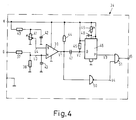
- Fig. 4 den bei der Schaltungsanordnung nach Fig. 2 verwendeten Verzögerungsschalter und
- Fig. 5 die Impulsfolgediagramme des Verzögerungsschalters nach Fig. 4,
- Fig. 6 die bei der Schaltungsanordnung nach Fig. 2 verwendete Zündeinheit.
- 1 shows a pulse diagram of the current with which a high-pressure gas discharge lamp can be operated,
- 2 shows a circuit arrangement for starting and operating a high-pressure gas discharge lamp which is located in the bridge branch of a capacitive half-bridge,
- 3 shows the duty cycle controller with clock generator used in the circuit arrangement according to FIG. 2,
- Fig. 4 shows the delay switch used in the circuit arrangement according to Fig. 2 and
- 5 shows the pulse sequence diagrams of the delay switch according to FIG. 4,
- 6 shows the ignition unit used in the circuit arrangement according to FIG. 2.
In Fig. 1 ist das Impulsdiagramm des bipolaren Versorgungsstromes I einer Hochdruckgasentladungslampe dargestellt, wobei td die Impulsbreite der Rechteckimpulse und to die Impulspausen sind. Das Tastverhältnis ![]()
![]()
In Fig. 2 sind mit A und B Eingangsklemmen zum Anschließen an ein Wechselspannungsquelle von z.B. 220 V, 50 Hz bezeichnet. An diese Eingangsklemmen ist, gegebenenfalls über ein Hochfrequenznetzfilter, ein Brückengleichrichter 1 mit vier Dioden angeschlossen, dessem Ausgang ein Ladekondensator 2 parallel geschaltet ist.In Fig. 2, A and B are input terminals for connection to an AC voltage source of e.g. Designated 220 V, 50 Hz. A
Die Gleichrichteranordnung 1, 2 bildet eine Gleichspannungsquelle, an die eine Brückenschaltung nach Art einer kapazitiven Halbbrücke angeschlossen ist, die aus zwei in Reihe liegenden Kondensatoren 3 und 4 und zwei in Reihe geschalteten Leistungs-Feldeffekttransistoren (VMOS-Transistoren) 5 und 6 besteht. Im Brückenzweig der kapazitiven Halbbrücke ist eine mit einer Drosselspule 7 in Reihe liegende Hochdruckgasentladungslampe 8 angeordnet. Die Drosselspule 7 bildet die Primärwicklung eines Transformators. Parallel zu jedem der Transistoren 5 und 6 liegt eine Freilaufdiode 9 bzw. 10, welche die Aufgabe hat, die beim Abschalten des jeweils angesteuerten Transistors in der Drosselspule 7 induzierte Spannung über die Lampe 8 kurzzuschließen. Mit den beiden Transistoren 5 und 6 ist jeweils eine Diode 11 bzw. 12 in Reihe geschaltet; hierdurch wird verhindert, daß Freilaufströme über die in den Transistoren 5 und 6 integrierten Dioden fließen, wodurch eine unnötige Erwärmung der Transistoren 5 und 6 vermieden wird. Die Drosselspule 7 ist mit zwei zusätzlichen Sekundärwicklungen 7a und 7b versehen, an deren Anschlußklemmen C und D bzw. E und F Versorgungsspannungen für die Steuerelektronik abgenommen werden. Ferner befindet sich in Reihe mit der Lampe 8 eine Sekundärwicklung 13b eines Zündtransformators 13, dessen Primärwicklung 13a an eine Zündeinheit 14 angeschlossen ist, welche Zündimpulse zum Zünden der Lampe 8 liefern kann (Fig. 6). Ein Kondensator 15, der parallel über der Reihenschaltung von Lampe 8 und Zündtransformator 13 liegt, dient als Rückschlußkondensator für die vom Zündtransformator 13 erzeugten Hochspannungszündimpulse.The
Die Versorgungsspannung für die Steuerelektronik wird vor dem Zünden der Hochdruckgasentladungslampe 8 aus der gleichgerichteten Netzspannung erzeugt, wobei jedoch relativ hohe Verluste auftreten. Hierfür ist parallel zum Ladekondensator 2 eine Reihenschaltung, bestehend aus einer Diode 16, einem Widerstand 17, einem Transistor 18, einer Diode 19 und einer Zenerdiode 20, geschaltet. Parallel zur Zenerdiode 20 liegt ein Ladekondensator 21. Über der Zenerdiode 20 fällt, bedingt durch den aus den Bauelementen 16 bis 20 bestehenden Spannungsteiler, am Ladekondensator 21 am Punkt K eine Hilfsversorgungsspannung von z.B. 13 V= ab. Durch einen der Basis des Transistors 18 vorgeschalteten Widerstand 22 ist der Transistor 18 zunächst leitend geschaltet.The supply voltage for the control electronics is generated from the rectified mains voltage before the high-pressure gas discharge lamp 8 is ignited, although relatively high losses occur. For this purpose, a series circuit consisting of a
Wenn die Lampe 8 gezündet hat, wird in der Sekundärwicklung 7a der Drosselspule 7 eine stromabhängige hochfrequente Spannung erzeugt. Diese an den Klemmen C und D der Sekundärwicklung 7a abzunehmende Spannung wird einem Vollweggleichrichter 23 zugeführt, dessem Ausgang ein Ladekondensator 24 parallel geschaltet ist. Zwischen die Basis des Transistors 18 und der Minusleitung ist eine Reihenschaltung, bestehend aus einem Transistor 25 und einer Zenerdiode 26, geschaltet. Zwischen der Basis des Transistors 25 und dem positiven Ausgang des Vollweggleichrichters 23 liegt ein Widerstand 27 in Reihe mit einer Zenerdiode 28. Am Punkt G des Ladekondensators 24 entsteht somit eine Gleichspannung, welche den Transistor 25 nach Erreichen der Durchbruchspannung der Zenerdioden 26 und 28 über den Widerstand 27 und die Zenerdiode 28 leitend schaltet. Dadurch wird der Transistor 18 nichtleitend, wodurch die Hilfsspannungserzeugung aus der gleichgerichteten Netzspannung unterbrochen wird. Die Spannung am Punkt K wird jetzt ausschließlich aus der Sekundärwicklung 7a der Drosselspule 7 erzeugt. Zur Entkopplung beider Stromkreise dienen die Dioden 19 und 29. Ein zwischen den positiven Ausgang des Vollweggleichrichters 23 und die Diode 29 geschalteter Widerstand 30 dient zur Strombegrenzung der aus der Sekundärwicklung 7a und dem Vollweggleichrichter 23 erzeugten Versorgungsspannung am Punkt K. Ein dem Transistor 25 und der Zenerdiode 26 parallel geschalteter Kondensator 31 wird zur Siebung noch vorhandener Niederfrequenzanteile (z.B. 300 Hz) benötigt.When the lamp 8 has ignited, the secondary winding 7a of the choke coil 7 becomes a current-dependent one high-frequency voltage generated. This voltage to be taken from the terminals C and D of the secondary winding 7a is fed to a full-
Die beiden als Halbleiterschalter dienenden Feldeffekt-Transistoren 5 und 6 werden mit Hilfe eines Schaltreglers 32 über jeweils eine Treiberstufe gesteuert. Die Spannungsversorgung des Schaltreglers 32 erfolgt aus der Sekundärwicklung 7b der Drosselspule 7. Der Schaltregler 32 steht mit einem Tastverhältnisregler 33 mit Taktgenerator 65 in Verbindung. Dem Tastverhältnisregler 33 wiederum ist ein Verzögerungsschalter 34 vorgeschaltet. Der Tastverhältnisregler 33 liefert zwei im festen Verhältnis zueinander stehende Rechteckimpulsfolgen, deren Impulsbreiten einstellbar sind. In Reihe mit den beiden Brückenkondensatoren 3 und 4 liegt ein Widerstand 35 und in Reihe mit den beiden Brückentransistoren 5 und 6 ein Widerstand 36. Die an den Widerständen 35 und 36 abfallenden Spannungen U1 und U2 werden dem Schaltregler 32 zugeführt und dienen als Regelgrößen zur Stabilisierung des Lampenstromes. Die eine aus dem Tastverhältnisregler 33 stammende Rechteckimpulsfolge steuert in Verknüpfung mit der am Widerstand 35 abfallenden Spannung U2 über den Schaltregler 32 den Brückentransistor 5, während die zweite Rechteckimpulsfolge mit der am Widerstand 36 abfallenden Spannung U1 den Brückentransistor 6 ansteuert.The two field-
Der Schaltregler 32 bildet zusammen mit dem Tastverhältnisregler 33 und dem Verzögerungsschalter 34 die Steuereinheit im Sinne der Erfindung.The switching
Einzelheiten des Verzögerungsschalters 34 sind in Fig. 4 dargestellt. Die Spannung am Punkt G wird über einen aus Widerständen 37 und 38 bestehenden Spannungsteiler als Spannung U3 auf den ersten Eingang M eines Komparators 39 geschaltet, wo sie verglichen wird mit der am Punkt K erzeugten Hilfsspannung, die dem zweiten Eingang N des Komparators 39 über einen aus Widerständen 40 und 41 bestehenden Spannungsteiler als Spannung U4 zugeführt wird. Kondensatoren 42 und 43 dienen zur Unterdrückung von Störspannungen. Widerstand 44 ist der Arbeitswiderstand des Komparators 39. Ein Widerstand 45 hält den Eingang O einer nachfolgenden monostabilen Kippstufe 46 im Ruhezustand auf H-Signal. Wenn die Spannung U3 während der Startphase der Lampe 8 am ersten Eingang M des Komparators 39 größer wird als die Spannung U4 am zweiten Komparatoreingang N (Fig. 5a), macht das Ausgangssignal V1 des Komparators 39 einen H-L Sprung (Fig. 5b). Hierbei wird ein zwischen dem Komparator 39 und der monostabilen Kippstufe 46 liegender Kondensator 47 und damit die Eingangsspannung V2 der monostabilen Kippstufe 46 kurzzeitig auf L-Potential gezogen (Fig. 5c), wodurch am Ausgang P der monostabilen Kippstufe 46 entsprechend der durch einen Kondensator 48 und einen Widerstand 49 bedingten Zeitkonstanten ein H-L-H Impuls V3 erzeugt wird (Fig. 5d). Für das zeitverzögerte Umschalten des Tastverhältnisses ist nur der L-H Übergang wichtig. Das Ausgangssignal V1 des Komparators 39 wird ferner auf den Eingang eines Inverters 50 geschaltet, dessen Ausgangssignal V4 (Fig. 5e) zusammen mit dem Ausgangssignal V3 der monostabilen Kippstufe 46 auf die Eingänge eines UND-Gatters 51 geschaltet werden. Dadurch wird erreicht, daß das Ausgangssignal V5 des UND-Gatters 51 und damit des Verzögerungsschalters 34 solange auf L-Signal bleibt, bis der L-H Übergang der monostabilen Kippstufe 46 erfolgt (Fig. 5f). In Fig. 5 sind die Impulsfolgediagramme des Verzögerungsschalters 34 dargestellt.Details of the
Der L-H Übergang wird nun benutzt, um im Tastverhältnisregler 33 (Fig. 3) das Tastverhältnis vom Starttastverhältnis auf das stationäre Betriebstastverhältnis umzuschalten. Als Taktgenerator 65 wurde der Baustein TL 494 CN von Texas Instr. benutzt. Seine Impulsfolgefrequenz wird bestimmt durch den Kondensator 52 und der am Spannungsteiler, bestehend aus den Widerständen 53 und 54, abfallenden Spannung. Die Kondensatoren 55, 56 und 57 verhindern Störspannungseinflüsse. Vor dem Start der Lampe 8 ist das vom Verzögerungsschalter 34 kommende Signal V5, welches dem Eingang Q des Tastverhältnisreglers 33 zugeführt wird, auf L-Potential. In diesem Falle liegt am Steuereingang K für das Tastverhältnis des Tastverhältnisreglers 33 eine vernachlässigbar kleine Spannung. Da ein im Tastverhältnisregler 33 vorhandener Feldeffekttransistor 58 noch hochohmig geschaltet ist, wird die Spannung bestimmt durch das Teilerverhältnis der Widerstände 59, 60 und 61. Sobald die Lampe 8 gezündet hat, erfolgt mit der eingestellten Verzögerungszeit am Eingang Q des Tastverhältnisreglers 33 ein L-H Übergang. Mit diesem H-Signal wird der Transistor 58 über einen Widerstand 62 leitend geschaltet. Die am Potentiometerwiderstand 61 abgegriffene und dem Eingang des Taktgenerators 65 zugeführte Steuerspannung steigt nun entsprechend dem Teilerverhältnis der Widerstände 59, 61 an, was zu einer Erniedrigung des Tastverhältnisses der Ausgangssignale an den Ausgängen S und T führt. An den Ausgangswiderständen 63 und 64 stehen jetzt Signale an, mit denen die beiden Brückentransistoren 5 und 6 über den Schaltregler 32 gesteuert werden.The LH transition is now used to switch the duty cycle from the start duty cycle to the stationary operating duty cycle in the duty cycle controller 33 (FIG. 3). The TL 494 CN module from Texas Instr. used. Its pulse repetition frequency is determined by the
Das vom Verzögerungsschalter 34 kommende Signal V5 wird außerdem dem Eingang W der Zündeinheit 14 zugeführt, deren Schaltung und Funktionsweise nunmehr anhand der Fig. 6 beschrieben wird.The signal V5 coming from the
Die mit Plus und Minus bezeichneten Klemmen der Zündeinheit 14 sind an den Ausgang des Brückengleichrichters 1 angeschlossen (Fig. 2). Die Klemen X und Y sind mit der Primärwicklung 13a des Zündtransformators 13 verbunden. Zwischen der Klemme X und dem Minusanschluß liegt ein Impulskondensator 66. Zwischen die Klemme Y und den Minusanschluß ist ein Thyristor 67 geschaltet, der über einen Widerstand 68 mit der Plusklemme verbunden ist. An die Zündelektrode des Thyristors 67 schließt sich ein Widerstand 69 und ein Diac 70 an, der einerseits über einen Kondensator 71 mit dem Minusanschluß und über einen Widerstand 72 mit der Plusklemme verbunden ist. Parallel zum Kondensator 71 ist eine aus einem Transistor 73 und einem Widerstand 74 bestehende Serienschaltung gelegt. Die Basis des Transistors 73 ist über einen Widerstand 75 mit dem Eingang W der Zündeinheit 14 verbunden. Ein Kondensator 76 zwischen der Basis und dem Emitter des Transistors 73 dient zur Störspanungsunterdrückung.The terminals of the
Wie bereits erwähnt, ist der Eingang W der Zündeinheit 14 mit dem Ausgang des Verzögerungsschalters 34 verbunden. Vor dem Starten der Lampe liegt auf dem Eingang W der Zündeinheit 14 L-Potential (Fig. 5f). Der Transistor 73 ist dadurch über den Widerstand 75 nichtleitend geschaltet. Der Impulskondensator 66 ist über den Widerstand 68 und die Primärwicklung 13a des Zündtransformators 13 aufgeladen. Über den Widerstand 72 lädt sich der Kondensator 71 bis zum Erreichen der Schwellenspannung des Diacs 70 (etwa 30 V) auf. Dann schlägt der Diac 70 durch, so daß der Entladestrom des Kondensators 71 über den Widerstand 69 den Thyristor 67 zündet. Dieser geht in seinen leitenden Zustand über, so daß sich der über den Widerstand 68 aufgeladene Impulskondensator 66 nun über die Primärwicklung 13a des Zündtransformators 13 zwischen den Anschlüssen X und Y entlädt, wodurch ein Hochspannungs-Zündimpuls in der Sekundärwicklung 13b des Zündtransformators 13 erzeugt wird. Nach jedem Zündimpuls schaltet sich der Thyristor 67 selbsttätig wieder in seinen nichtleitenden Zustand.As already mentioned, the input W of the
Für das zeitverzögerte Abschalten der Zündeinheit ist der L-H-Übergang im Verzögerungsschalter 34 bestimmend (Fig. 5f). Der Zündvorgang wiederholt sich nämlich solange, bis der Transistor 73 durch den Übergang vom L-auf das H-Signal am Eingang W der Zündeinheit 14 leitend geschaltet wird. Hierdurch wird das Potential am Punkt Z zwischen dem Widerstand 72 und dem Kondensator 71 unter die Schwellenspannung des Diacs 70 gezogen, wodurch die Zündimpulse abgeschaltet werden.The LH transition in the
Bei einem Ausführungsbeispiel zum Starten und Betrieb einer 30 W-Natriumhochdruckentladungslampe mit bipolaren Impulsen betrug die Impulsfolgefrequenz 300 Hz, der eine höherfrequente Spannung zwischen 30 und 70 KHz überlagert war. Das Starttastverhältnis war auf etwa 0,7 und das Betriebstastverhältnis auf etwa 0,5 eingestellt. Die verwendeten Bauelemente wiesen folgende Werte auf:
Claims (8)
- A circuit arrangement for starting and operating a high-pressure gas discharge lamp by means of a voltage converter comprising at least one semiconductor switch which can be periodically switched to the conductive and to the non-conductive state by a control unit in such a manner that the lamp receives a pulsatory supply current having a duty cycle in the operating condition (operating duty cycle) between 0.1 and 0.7, characterized in that the control unit (32, 33, 34) can switch the semiconductor switches (5,6) upon starting of the lamp (8) with a duty cycle during starting (starting duty cycle) which is increased with respect to the operating duty cycle, and in that the starting duty cycle exceeds the operating duty cycle by at least 0. 2.
- A circuit arrangement as claimed in Claim 1, characterized in that the control unit (32, 33, 34) comprises a delay switch (34) having a time constant for maintaining the starting duty cycle for a constant time after ignition of the lamp (8).
- A circuit arrangement as claimed in Claim 1, characterized in that the control unit (32, 33, 34) reduces the starting duty cycle to the operating duty cycle after the ignition of the lamp (8) in dependence on a signal which is proportional to the lamp voltage.
- A circuit arrangement as claimed in any one of Claims 1 to 3, characterized in that the control unit (32, 33, 34) controls the periodic switching of the semiconductor switch (5, 6) after the ignition of the lamp (8) in such a manner that the starting duty cycle can be reduced abruptly to the operating duty cycle thereby.
- A circuit arrangement as claimed in any one of Claims 1 to 3, characterized in that the control unit (32, 33, 34) controls the periodic switching of the semiconductor switch (5, 6) in such a manner that the starting duty cycle can be reduced gradually to the operating duty cycle thereby.
- A circuit arrangement as claimed in Claim 2 or 3, in which a secondary winding (13b) of an ignition transformer (13) for producing high-frequency ignition pulses is connected in series with the high-pressure gas discharge lamp (8) and a primary winding (13a) of this transformer is connected to an ignition unit (14), characterized in that the ignition unit (14) is connected to an output of the delay switch (34) in order that the ignition unit can be switched off with a delay of at least 0.1 s after the ignition of the lamp.
- A circuit arrangement as claimed in Claims 2 and 6, characterized in that the ignition unit is switched off with a delay of at least 0.1 s after a given value of the lamp current has been attained.
- A circuit arrangement as claimed in Claim 7, characterized in that a choke coil (7) is connected in series with the high-pressure gas discharge lamp (8) and takes the form of the primary winding of a transformer whose secondary winding (7a) produces a voltage proportional to the lamp current and is connected to the delay switch (34).
Priority Applications (1)
| Application Number | Priority Date | Filing Date | Title |
|---|---|---|---|
| AT88201822T ATE96977T1 (en) | 1987-09-03 | 1988-08-26 | CIRCUIT ARRANGEMENT FOR STARTING A HIGH PRESSURE GAS DISCHARGE LAMP. |
Applications Claiming Priority (2)
| Application Number | Priority Date | Filing Date | Title |
|---|---|---|---|
| DE19873729383 DE3729383A1 (en) | 1987-09-03 | 1987-09-03 | CIRCUIT ARRANGEMENT FOR STARTING A HIGH-PRESSURE DISCHARGE LAMP |
| DE3729383 | 1987-09-03 |
Publications (2)
| Publication Number | Publication Date |
|---|---|
| EP0306086A1 EP0306086A1 (en) | 1989-03-08 |
| EP0306086B1 true EP0306086B1 (en) | 1993-11-03 |
Family
ID=6335094
Family Applications (1)
| Application Number | Title | Priority Date | Filing Date |
|---|---|---|---|
| EP88201822A Expired - Lifetime EP0306086B1 (en) | 1987-09-03 | 1988-08-26 | Circuit arrangement for starting a high-pressure gas discharge lamp |
Country Status (5)
| Country | Link |
|---|---|
| US (1) | US4937501A (en) |
| EP (1) | EP0306086B1 (en) |
| JP (1) | JPS6472496A (en) |
| AT (1) | ATE96977T1 (en) |
| DE (2) | DE3729383A1 (en) |
Families Citing this family (28)
| Publication number | Priority date | Publication date | Assignee | Title |
|---|---|---|---|---|
| FR2644314A1 (en) * | 1989-03-10 | 1990-09-14 | Harel Jean Claude | ELECTRONIC STARTING AND SUPPLY DEVICE FOR FLUORESCENT TUBES WITH PREHEATABLE ELECTRODES |
| FI903403A0 (en) * | 1989-07-10 | 1990-07-05 | Philips Corp | KRETTSSAMMANSTAELLNING. |
| ATE120066T1 (en) * | 1990-01-29 | 1995-04-15 | Philips Electronics Nv | SWITCHING ARRANGEMENT. |
| ATE120067T1 (en) * | 1990-01-29 | 1995-04-15 | Philips Electronics Nv | SWITCHING ARRANGEMENT. |
| DE4015398A1 (en) * | 1990-05-14 | 1991-11-21 | Hella Kg Hueck & Co | Starter control circuit for HV gas discharge lamp in road vehicle |
| US5051665A (en) * | 1990-06-21 | 1991-09-24 | Gte Products Corporation | Fast warm-up ballast for arc discharge lamp |
| US5270620A (en) * | 1990-09-04 | 1993-12-14 | General Electric Company | High frequency resonant converter for operating metal halide lamps |
| JP2587718B2 (en) * | 1990-10-01 | 1997-03-05 | 株式会社小糸製作所 | Lighting circuit for vehicle discharge lamps |
| DE4039161C2 (en) * | 1990-12-07 | 2001-05-31 | Zumtobel Ag Dornbirn | System for controlling the brightness and operating behavior of fluorescent lamps |
| JPH06503203A (en) * | 1991-01-09 | 1994-04-07 | ウエルチ.アリン.インコーポレイテッド | low wattage metal halide lamp equipment |
| US5261916A (en) * | 1991-12-12 | 1993-11-16 | Target Therapeutics | Detachable pusher-vasoocclusive coil assembly with interlocking ball and keyway coupling |
| US5320770A (en) * | 1992-04-27 | 1994-06-14 | Dow Corning Corporation | Electrorheological (ER) fluid based on amino acid containing metal polyoxo-salts |
| DE9315239U1 (en) * | 1993-10-08 | 1994-11-17 | Niggemeyer Gert Guenther | Circuit for operating a plasma |
| GB2298749B (en) * | 1994-03-04 | 1998-01-07 | Int Rectifier Corp | Electronic ballasts for gas discharge lamps |
| DE4439812A1 (en) * | 1994-11-08 | 1996-05-09 | Bosch Gmbh Robert | Device for operating a gas discharge lamp |
| US5530321A (en) * | 1995-02-21 | 1996-06-25 | Sears; Lawrence M. | Power supply for a gas discharge lamp |
| DE19608655A1 (en) * | 1996-03-06 | 1997-09-11 | Bosch Gmbh Robert | Power control of a high-pressure gas discharge lamp operated with alternating current, in particular for motor vehicles |
| EP0955793B1 (en) * | 1998-05-08 | 2004-03-03 | Denso Corporation | Discharge lamp apparatus |
| US6097162A (en) * | 1998-08-17 | 2000-08-01 | Alliedsignal Inc. | Power supply system for a fluorescent lamp |
| US6369518B1 (en) * | 1999-01-28 | 2002-04-09 | Matsoshita Electric Works R & D Laboratories Inc | Lamps with electronic control of color temperature and color rendering index |
| DE19922039A1 (en) * | 1999-05-12 | 2000-11-16 | Patent Treuhand Ges Fuer Elektrische Gluehlampen Mbh | Fluorescent lamp choke for a gas discharge lamp and method for operating it includes a DC-AC converter fed by a DC source having a bridge circuit with first and second controllable switches fitted parallel to the DC source. |
| JP4724908B2 (en) * | 2000-09-26 | 2011-07-13 | 岩崎電気株式会社 | HID lamp lighting circuit |
| US6504313B1 (en) * | 2000-10-13 | 2003-01-07 | Koninklijke Philips Electronics N.V. | Ignition scheme for electronic HID ballast |
| CN1321547C (en) * | 2001-01-12 | 2007-06-13 | 松下电工株式会社 | Ballast for a discharge lamp |
| DE10319511A1 (en) * | 2003-04-30 | 2004-11-18 | Tridonicatco Gmbh & Co. Kg | Ignition circuit with regulated ignition voltage |
| DE102008016754A1 (en) * | 2008-03-31 | 2009-10-01 | Tridonicatco Gmbh & Co. Kg | Low-voltage supply in control gear for bulbs |
| DE102009019625B4 (en) * | 2009-04-30 | 2014-05-15 | Osram Gmbh | A method of determining a type of gas discharge lamp and electronic ballast for operating at least two different types of gas discharge lamps |
| JP2011009088A (en) * | 2009-06-25 | 2011-01-13 | Panasonic Electric Works Co Ltd | Discharge lamp lighting device and lighting system using it |
Family Cites Families (6)
| Publication number | Priority date | Publication date | Assignee | Title |
|---|---|---|---|---|
| US3999100A (en) * | 1975-05-19 | 1976-12-21 | Morton B. Leskin | Lamp power supply using a switching regulator and commutator |
| US4128789A (en) * | 1976-06-30 | 1978-12-05 | General Electric Company | Method of operating gaseous discharge lamps |
| US4527099A (en) * | 1983-03-09 | 1985-07-02 | Lutron Electronics Co., Inc. | Control circuit for gas discharge lamps |
| FI68747C (en) * | 1984-02-17 | 1985-10-10 | Helvar Oy | LIGHT RELEASE FOR MEDICAL ELECTRONIC SYSTEMS FOR FORED LAMPS |
| AU4214285A (en) * | 1984-03-28 | 1985-11-01 | Electronic Transformer Corp. | Ballast and control unit for electric discharge lamp |
| DE3530638A1 (en) * | 1985-08-28 | 1987-03-05 | Philips Patentverwaltung | CIRCUIT ARRANGEMENT FOR STARTING AND OPERATING GAS DISCHARGE LAMPS |
-
1987
- 1987-09-03 DE DE19873729383 patent/DE3729383A1/en not_active Withdrawn
-
1988
- 1988-08-26 DE DE88201822T patent/DE3885391D1/en not_active Expired - Fee Related
- 1988-08-26 AT AT88201822T patent/ATE96977T1/en active
- 1988-08-26 EP EP88201822A patent/EP0306086B1/en not_active Expired - Lifetime
- 1988-08-29 US US07/238,022 patent/US4937501A/en not_active Expired - Fee Related
- 1988-08-31 JP JP63215311A patent/JPS6472496A/en active Pending
Also Published As
| Publication number | Publication date |
|---|---|
| DE3885391D1 (en) | 1993-12-09 |
| ATE96977T1 (en) | 1993-11-15 |
| DE3729383A1 (en) | 1989-03-16 |
| EP0306086A1 (en) | 1989-03-08 |
| JPS6472496A (en) | 1989-03-17 |
| US4937501A (en) | 1990-06-26 |
Similar Documents
| Publication | Publication Date | Title |
|---|---|---|
| EP0306086B1 (en) | Circuit arrangement for starting a high-pressure gas discharge lamp | |
| DE2642272C2 (en) | Ballast arrangement for gas discharge lamps with short deionization times | |
| EP0056642B1 (en) | Method and circuit for heating, starting and driving or controlling the light current of low pressure gas discharge lamps | |
| EP0359860A1 (en) | Device and method for operating at least one discharge lamp | |
| DE60006046T2 (en) | Ballast for high voltage gas discharge lamp | |
| DE3231939C2 (en) | ||
| DE60205830T2 (en) | Ballast with efficient electrode preheating and lamp fault protection | |
| DE4014391A1 (en) | LIGHTING SYSTEM FOR COMPACT FLUORESCENT TUBES | |
| DE2705968A1 (en) | STARTER AND CIRCUIT ARRANGEMENT FOR GAS DISCHARGE LAMP | |
| DE3829388A1 (en) | CIRCUIT ARRANGEMENT FOR OPERATING A LOAD | |
| DE19653604A1 (en) | Ballast unit for starting fluorescent lamp | |
| DE69911376T2 (en) | METHOD AND ARRANGEMENT FOR OPERATING ELECTRONIC CONTROL GEARS FOR DISCHARGE LAMPS OF HIGH INTENSITY | |
| DE3711814C2 (en) | Electronic ballast for operating fluorescent lamps | |
| DE19712258A1 (en) | Circuit for igniting a high-pressure discharge lamp | |
| EP0614052A2 (en) | Automatic ignition device | |
| DE19849738A1 (en) | Pulse generator | |
| DE2835044A1 (en) | LOAD SWITCH FOR FLUORESCENT LAMPS | |
| AT397326B (en) | CIRCUIT FOR THE IGNITION AND OPERATION OF GAS DISCHARGE LAMPS | |
| EP0111373B1 (en) | Circuit arrangement for starting and operating high pressure gas discharge lamps | |
| DE60122192T2 (en) | CIRCUIT | |
| DE3338464A1 (en) | High-frequency brightness control for fluorescent lamps | |
| DE3530638A1 (en) | CIRCUIT ARRANGEMENT FOR STARTING AND OPERATING GAS DISCHARGE LAMPS | |
| DE2527086A1 (en) | BURNER IGNITION ARRANGEMENT | |
| DE69930897T2 (en) | Arrangement for operating a discharge lamp | |
| DE3607109C1 (en) | Ballast for discharge lamps |
Legal Events
| Date | Code | Title | Description |
|---|---|---|---|
| PUAI | Public reference made under article 153(3) epc to a published international application that has entered the european phase |
Free format text: ORIGINAL CODE: 0009012 |
|
| AK | Designated contracting states |
Kind code of ref document: A1 Designated state(s): AT BE DE FR GB NL |
|
| 17P | Request for examination filed |
Effective date: 19890830 |
|
| 17Q | First examination report despatched |
Effective date: 19910322 |
|
| GRAA | (expected) grant |
Free format text: ORIGINAL CODE: 0009210 |
|
| AK | Designated contracting states |
Kind code of ref document: B1 Designated state(s): AT BE DE FR GB NL |
|
| REF | Corresponds to: |
Ref document number: 96977 Country of ref document: AT Date of ref document: 19931115 Kind code of ref document: T |
|
| REF | Corresponds to: |
Ref document number: 3885391 Country of ref document: DE Date of ref document: 19931209 |
|
| GBT | Gb: translation of ep patent filed (gb section 77(6)(a)/1977) |
Effective date: 19940127 |
|
| ET | Fr: translation filed | ||
| PLBE | No opposition filed within time limit |
Free format text: ORIGINAL CODE: 0009261 |
|
| STAA | Information on the status of an ep patent application or granted ep patent |
Free format text: STATUS: NO OPPOSITION FILED WITHIN TIME LIMIT |
|
| 26N | No opposition filed | ||
| REG | Reference to a national code |
Ref country code: FR Ref legal event code: CD |
|
| NLT1 | Nl: modifications of names registered in virtue of documents presented to the patent office pursuant to art. 16 a, paragraph 1 |
Owner name: PHILIPS ELECTRONICS N.V. |
|
| PGFP | Annual fee paid to national office [announced via postgrant information from national office to epo] |
Ref country code: BE Payment date: 19950816 Year of fee payment: 8 |
|
| PGFP | Annual fee paid to national office [announced via postgrant information from national office to epo] |
Ref country code: NL Payment date: 19950830 Year of fee payment: 8 |
|
| PGFP | Annual fee paid to national office [announced via postgrant information from national office to epo] |
Ref country code: GB Payment date: 19960731 Year of fee payment: 9 |
|
| PGFP | Annual fee paid to national office [announced via postgrant information from national office to epo] |
Ref country code: FR Payment date: 19960828 Year of fee payment: 9 |
|
| PG25 | Lapsed in a contracting state [announced via postgrant information from national office to epo] |
Ref country code: BE Effective date: 19960831 |
|
| PGFP | Annual fee paid to national office [announced via postgrant information from national office to epo] |
Ref country code: AT Payment date: 19960913 Year of fee payment: 9 |
|
| BERE | Be: lapsed |
Owner name: PHILIPS ELECTRONICS N.V. Effective date: 19960831 |
|
| PG25 | Lapsed in a contracting state [announced via postgrant information from national office to epo] |
Ref country code: NL Effective date: 19970301 |
|
| NLV4 | Nl: lapsed or anulled due to non-payment of the annual fee |
Effective date: 19970301 |
|
| PG25 | Lapsed in a contracting state [announced via postgrant information from national office to epo] |
Ref country code: GB Free format text: LAPSE BECAUSE OF NON-PAYMENT OF DUE FEES Effective date: 19970826 Ref country code: AT Free format text: LAPSE BECAUSE OF NON-PAYMENT OF DUE FEES Effective date: 19970826 |
|
| PGFP | Annual fee paid to national office [announced via postgrant information from national office to epo] |
Ref country code: DE Payment date: 19971219 Year of fee payment: 10 |
|
| GBPC | Gb: european patent ceased through non-payment of renewal fee |
Effective date: 19970826 |
|
| PG25 | Lapsed in a contracting state [announced via postgrant information from national office to epo] |
Ref country code: FR Free format text: LAPSE BECAUSE OF NON-PAYMENT OF DUE FEES Effective date: 19980430 |
|
| REG | Reference to a national code |
Ref country code: FR Ref legal event code: ST |
|
| PG25 | Lapsed in a contracting state [announced via postgrant information from national office to epo] |
Ref country code: DE Free format text: LAPSE BECAUSE OF NON-PAYMENT OF DUE FEES Effective date: 19990601 |