EP0305877A2 - Vorrichtung zur Verwendung in einer Servolenkung - Google Patents
Vorrichtung zur Verwendung in einer Servolenkung Download PDFInfo
- Publication number
- EP0305877A2 EP0305877A2 EP88113778A EP88113778A EP0305877A2 EP 0305877 A2 EP0305877 A2 EP 0305877A2 EP 88113778 A EP88113778 A EP 88113778A EP 88113778 A EP88113778 A EP 88113778A EP 0305877 A2 EP0305877 A2 EP 0305877A2
- Authority
- EP
- European Patent Office
- Prior art keywords
- fluid
- main conduit
- pressure
- bypass valve
- fluid pressure
- Prior art date
- Legal status (The legal status is an assumption and is not a legal conclusion. Google has not performed a legal analysis and makes no representation as to the accuracy of the status listed.)
- Granted
Links
- 239000012530 fluid Substances 0.000 claims abstract description 154
- 230000007246 mechanism Effects 0.000 claims description 12
- 238000013022 venting Methods 0.000 claims 1
- 230000007423 decrease Effects 0.000 abstract description 2
- 238000010276 construction Methods 0.000 description 4
- 238000012986 modification Methods 0.000 description 2
- 230000004048 modification Effects 0.000 description 2
- 238000011144 upstream manufacturing Methods 0.000 description 2
- 230000000977 initiatory effect Effects 0.000 description 1
- 238000004519 manufacturing process Methods 0.000 description 1
Images


Classifications
-
- F—MECHANICAL ENGINEERING; LIGHTING; HEATING; WEAPONS; BLASTING
- F04—POSITIVE - DISPLACEMENT MACHINES FOR LIQUIDS; PUMPS FOR LIQUIDS OR ELASTIC FLUIDS
- F04C—ROTARY-PISTON, OR OSCILLATING-PISTON, POSITIVE-DISPLACEMENT MACHINES FOR LIQUIDS; ROTARY-PISTON, OR OSCILLATING-PISTON, POSITIVE-DISPLACEMENT PUMPS
- F04C14/00—Control of, monitoring of, or safety arrangements for, machines, pumps or pumping installations
- F04C14/24—Control of, monitoring of, or safety arrangements for, machines, pumps or pumping installations characterised by using valves controlling pressure or flow rate, e.g. discharge valves or unloading valves
- F04C14/26—Control of, monitoring of, or safety arrangements for, machines, pumps or pumping installations characterised by using valves controlling pressure or flow rate, e.g. discharge valves or unloading valves using bypass channels
-
- B—PERFORMING OPERATIONS; TRANSPORTING
- B62—LAND VEHICLES FOR TRAVELLING OTHERWISE THAN ON RAILS
- B62D—MOTOR VEHICLES; TRAILERS
- B62D6/00—Arrangements for automatically controlling steering depending on driving conditions sensed and responded to, e.g. control circuits
Definitions
- the present invention relates to a power steering system having a bypass valve which directs excess fluid flow from a pump to reservoir.
- a known power steering system includes a pump, a steering control valve which is actuated by turning of a vehicle steering wheel, and a power steering motor for assisting in moving the vehicle wheels in response to actuation of the control valve.
- the pump is driven by the engine and provides fluid at a flow rate which varies as a function of the speed of operation of the engine. At high engine operating speeds, the output of the pump is substantially greater than at low engine operating speeds.
- a bypass valve directs excess fluid flow from the pump to the reservoir.
- the bypass flow control valve is controlled (i) in response to the fluid flow rate through the flow control orifice and (ii) in response to a pressure drop created by a small pilot fluid flow from the outlet of the pump through a variable orifice.
- the variable orifice is provided by a solenoid actuated valve located in the pilot fluid flow conduit.
- the solenoid actuated valve is controlled in response to vehicle speed, and acts to reduce fluid flow to the power steering motor as vehicle speed increases and while steering is occurring.
- a solenoid actuated valve in a power steering system, in the manner disclosed in the aforementioned U.S. Patent No. 4,691,797, could be objectionable. This is because under at least certain operating conditions, a solenoid actuated valve may not be as durable as a mechanical or fluid pressure actuated valve. In addition, it is believed that a mechanical or fluid actuated valve is simpler and easier to manufacture and install in a power steering system than a solenoid actuated valve.
- a power steering system constructed in accordance with the present invention includes a bypass valve assembly which bypasses fluid from a main conduit connected with a power steering pump and power steering motor.
- the bypass valve assembly is urged toward an open condition, bypassing fluid from the main conduit, with a force which varies as a function of the fluid pressure drop across an orifice in the main conduit.
- the bypass valve assembly is urged toward a closed condition by a spring and by fluid pressure.
- a pressure responsive pilot valve assembly provides the fluid pressure for urging the bypass valve toward the closed condition.
- the pressure responsive pilot valve assembly operates to increase the fluid pressure force urging the bypass valve assembly closed. This decreases the rate at which fluid from the power steering pump is bypassed to thereby increase the amount of fluid available for actuation of the power steering motor. Since the pilot valve assembly is actuated by fluid pressure rather than a solenoid, the objections to solenoid operated valves are not applicable to the pressure responsive pilot valve assembly.
- the bypass valve is actuated as a function of demand for fluid by the power steering motor.
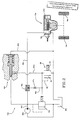
- a vehicle power steering system 10 (Fig. 1) includes a power steering mechanism 12 which is operable in response to rotation of a vehicle steering wheel (not shown) to turn steerable vehicle wheels 14 and 16.
- the power steering mechanism 12 includes an open center power steering control valve 18 which is operable, in response to rotation of the steering wheel, to port fluid under pressure to a power steering motor 20.
- the power steering motor 20 is connected with the steerable vehicle wheels 14 and 16 by a known steering linkage 22.
- the construction of the power steering mechanism 12 is described in U.S. Patent No. 3,606,819 issued September 21, 1971 and entitled Power Steering Gear Assembly. Other known power steering mechanisms could be used if desired.
- a power steering pump 26 is driven by an engine of the vehicle to supply fluid under pressure to the power steering mechanism 12.
- the pump 26 draws fluid from a tank or reservoir 28.
- the pump 26 discharges fluid to a main conduit 30 which connects the pump in fluid communication with the power steering control valve 18.
- a bypass valve assembly 34 directs excess fluid flow from the pump 26 back to the reservoir 28.
- a flow of fluid under pressure from the pump 26 is, during nonsteering conditions, conducted to the reservoir 28 through the open center power steering control valve 18 and through the bypass valve assembly 34.
- the higher the engine operating speed the greater is the output from the pump 26 and the more fluid which is directed to the reservoir 28 through the bypass valve assembly 34.
- the amount of fluid directed to the reservoir 28 through the bypass valve assembly 34 is reduced depending upon the demand for fluid by the power steering mechanism 12.
- a flow control orifice 38 is disposed in the main conduit 30.
- the flow control orifice 38 is connected with the power steering pump 26 by a first section 40 of the main conduit 30 and is connected with the power steering control valve 18 by a second section 42 of the main conduit 30.
- the flow control orifice 38 could have many different constructions, in one specific embodiment of the invention, the orifice 38 is a venturi having the construction illustrated in U.S. Patent No. 3,384,020 issued May 21, 1968 and entitled Pump.
- a control pressure conduit 46 is connected to the throat of the flow control orifice 38 through a secondary orifice 47.
- the conduit 46 conducts a hydraulic control signal which varies as a function of the rate of flow through the flow control orifice 38.
- the control pressure conduit 46 is connected in fluid communication with a pressure chamber 48 in the bypass valve assembly 34.
- the fluid pressure in the chamber 48 urges a bypass valve member 50 toward the illustrated closed condition.
- a biasing spring 52 is provided in the chamber 48 and acts with the fluid pressure in urging the bypass valve member 50 toward the closed condition.
- the bypass valve assembly 34 is urged toward the open condition by fluid pressure conducted from the first section 40 of the main conduit 30 through a pressure conduit 56. Since the first section 40 of the main conduit 30 is upstream of the flow control orifice 38, the fluid pressure in the conduit 56 will be greater than the pressure of the hydraulic control signal conducted through the conduit 46 from the flow control orifice. When the difference in the pressures in conduits 56 and 46 is sufficiently great, the force of the spring 52 will be overcome and the bypass valve member 50 will move to an open condition.
- the fluid pressure in the first section 40 of the main conduit 30 will substantially exceed the fluid pressure in the second section 42 of the main conduit 30.
- This pressure differential when it exceeds the force of spring 52, moves the bypass valve member 50 from the closed condition indicated in Fig. 1 to an open condition bypassing fluid back to the reservoir 28.
- the extent of movement of the bypass valve member 50 from the closed condition to an open condition will depend upon the amount by which the fluid pressure in the conduit 56 exceeds the fluid pressure in the conduit 46.
- the bypass valve member 50 moves to an open position to bypass fluid at a rate which is a function of the difference between the fluid pressures in the conduits 46 and 56.
- the power steering control valve 18 restricts fluid flow to the reservoir 28 and directs fluid flow to the power steering motor 20. Due to the resistance encountered by the power steering motor 20 in turning the steerable vehicle wheels 14 and 16, the fluid pressure in the second section 42 of the main conduit 30 increases. This results in the bypass valve member 50 moving toward the closed position.
- a pressure responsive pilot valve assembly 60 is provided to increase the force urging the bypass valve assembly 34 toward the closed condition whenever the fluid pressure in the first section 40 of the main conduit 30 exceeds a predetermined pressure. Actuation of the pilot valve assembly 60 provides a pilot pressure signal through a pilot conduit 64. The pilot fluid pressure signal modifies the flow control signal conducted through the conduit 46 to increase fluid pressure in the chamber 48 and the force urging the bypass valve assembly 34 toward the closed condition. By increasing the force urging the bypass valve assembly 34 toward its closed condition, the bypass valve member 50 moves to reduce and, perhaps, even stop the bypassing of fluid during a steering maneuver.
- the pressure responsive pilot valve assembly 60 is actuated from its closed condition to an open condition whenever the fluid pressure in the first section 40 of the main conduit 30 exceeds a predetermined pressure, the extent to which the pressure responsive pilot valve assembly is opened will vary depending upon the fluid pressure in the first section 40 of the main conduit 30.
- the pressure responsive pilot valve assembly 60 increases the fluid pressure urging the bypass valve assembly 34 toward its closed condition as a direct function of increases in resistance to operation of the power steering motor 22 upon actuation of the power steering control valve 18. If there is a relatively large resistance to turning of the steerable vehicle wheels 14 and 16, such as would be encountered during parking at low vehicle speeds, the pressure responsive pilot valve assembly 60 is actuated to a fully open condition. At this time, a relatively large fluid pressure signal is conducted to the pressure chamber 48 in the bypass valve assembly 34 to assist the spring 52 in moving the bypass valve member 50 toward a fully closed position.
- bypass valve assembly 34 moves toward a fully closed position so that a greater amount of the output of the pump 26 is available to perform a steering operation.
- pilot valve assembly 60 When the pilot valve assembly 60 is open, there will be a limited flow of fluid from the conduit 46 through the secondary orifice 47 to the conduit 42.
- the embodiment of the pilot valve assembly 60 illustrated in Fig. 1 includes an axially tapered pin 70 having a cylindrical body portion 72 and a conical nose end portion 74. An end of the pin 70 is connected with a piston 76 disposed in a cylindrical spring chamber 78. The piston 76 is urged toward the left (as viewed in Fig. 1) by a biasing spring 80 located in a spring chamber 78. The spring chamber 78 is connected with the reservoir 28 by a conduit 82 so that any fluid leakage in chamber 78 is communicated with the reservoir 28.
- the tapered pin When the fluid pressure against the conical nose end portion 74 of the tapered pin 70 is less than a predetermined pressure, the tapered pin is in the fully closed position illustrated in Fig. 1. At this time, the cylindrical body portion 72 of the pin blocks fluid communication between a pilot conduit 86, connected with the first section 40 of the main conduit 30, and the pilot conduit 64, connected with the bypass valve assembly 34.
- the fluid pressure applied against the nose end portion 74 of the tapered pin 70 increases and urges the pin away from the illustrated closed condition toward an open condition.
- the amount by which the fluid pressure in the first section 40 of the main conduit exceeds a predetermined fluid pressure determines the distance which the tapered pin 70 is moved toward the right (as viewed in Fig. 1) against the influence of the biasing spring 80.
- the pin 70 is moved through only a relatively small distance from the closed position illustrated in Fig. 1 to an open position. This results in a very small opening being formed around the nose 74 of the pin 70 to connect the pilot conduits 86 and 64 in fluid communication with each other.
- the pressure responsive pilot valve assembly 60 is operated from a closed condition to any one of many open conditions to modulate the fluid pressure force urging the bypass valve assembly 34 toward its closed condition as a function of the fluid pressure in the first section 40 of the main conduit 30, which is a function of the resistance to turning of the steerable vehicle wheels 14 and 16 during a steering operation.
- the resistance to operation of the power steering motor 20 causes the fluid pressure in both the first and second sections 40 and 42 of the main conduit 30 to increase.
- This causes the bypass valve assembly 34 to move toward a closed condition.
- the increase in fluid pressure in the first section 40 of the main conduit 30, if sufficient, causes the pressure responsive pilot valve assembly 60 to open.
- the fluid pressure from the pilot valve assembly 60 is transmitted to the pressure chamber 48 in the bypass valve assembly 34 to urge the bypass valve member 50 toward its closed position. This results in an increase in flow to the power steering motor.
- the extent to which the bypass valve member 50 moves toward its closed position will be determined by the pressure increase in the first section 40 of the main conduit 30.
- the increased load applied to the power steering motor results in the fluid pressure in the first section 40 of the main conduit 30 increasing to about 150 psi. This fluid pressure is sufficient to initiate actuation of the pressure responsive pilot valve assembly 60 from its closed condition.
- the fluid pressure in the first section 40 of the main conduit 30 will increase to about 1,000 psi, depending upon the load encountered by the steerable vehicle wheels 14 and 16. This fluid pressure is sufficient to maintain the pilot valve assembly 60 in an open position. It should be understood that the foregoing specific pressures for specific steering conditions have been set forth merely for purposes of illustration and not for purposes of limitation of the invention.
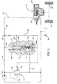
- the pressure relief valve assembly 90 is provided between the conduit 64a and reservoir 28a.
- the pressure relief valve assembly 90 includes a valve member 92 (shown schematically) which is urged to a closed position by a spring 94.
- the valve member 92 is urged toward an open condition by fluid pressure conducted through a conduit 96 from the pilot conduit 64a and control pressure conduit 46a. Whenever the fluid pressure in the pilot conduit 64a or control pressure conduit 46a exceeds a predetermined fluid pressure, the relief valve member 92 is moved to its open position to vent the conduits 46a and 64a to reservoir.
- the pilot flow control valve assembly 60a When the pressure relief valve assembly 90 is actuated, the pilot flow control valve assembly 60a will be at least partially opened. At this time, the pressure drop across the pilot flow control valve assembly 60a will be approximately the same as the pressure drop across the flow control orifice 38a and secondary orifice 47a. Therefore, a pressure equilibrium condition will exist in the conduits 46a and 64a.
- FIG. 2 there is a separate pressure relief valve assembly 90 and pilot flow control valve assembly 60a. Ease of assembly and compact construction can be promoted by combining the relief valve assembly 90 and pilot valve assembly 60a into a unitary structure in the manner illustrated in Fig. 3. Since the embodiment of the invention illustrated in Fig. 3 is generally similar to the embodiment of the invention illustrated in Figs. 1 and 2, similar numerals are utilized to designate similar components, the suffix letter "b" being associated with the components of the embodiment of the invention shown in Fig. 3 to avoid confusion.
- a pressure responsive pilot valve assembly 60b includes a tapered pin 70b which is urged toward its closed position, illustrated in Fig. 3, by a biasing spring 102.
- the biasing spring 102 also urges a relief valve member 92b in a relief valve assembly 90b toward its closed position.
- only one biasing spring is required to urge both the pilot valve assembly 60b and the relief valve assembly 90b to their closed conditions.
- the conical nose end portion 74b of the tapered pin 70b has a larger cross sectional area than the end portion of the relief valve member 92b which is exposed to the fluid pressure in the conduit 46b. Therefore, the tapered pin 70b in the pilot valve assembly 60b is moved to its fully open position before the relief valve member 92b moves away from its closed position illustrated in Fig. 3. However, after the pilot valve assembly 60b is operated to a fully open condition and the fluid pressure in the conduits 46b and 96b exceeds a predetermined fluid pressure, the pilot valve member 92b is moved from its closed position against the influence of the biasing spring 102 to vent the conduits 46b and 64b to reservoir 28b through a conduit 104.
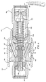
- Figs. 4 and 5 One specific preferred embodiment of the combined pilot valve assembly 60b and relief valve 90b of Fig. 3 is illustrated in Figs. 4 and 5. Since the embodiment of the invention illustrated in Figs. 4 and 5 is generally similar to the embodiments of the invention illustrated in Figs. 1-3, similar numerals are utilized to designate similar components, the suffix letter "c" being associated with the embodiment of Figs. 4 and 5 to avoid confusion.
- a pressure responsive pilot valve assembly 60c and a pressure relief valve assembly 90c are combined into one valve assembly 110.
- the pilot valve assembly 60c and pressure relief valve assembly 90c are enclosed within a common housing 112 which in turn is enclosed within a housing 114 (Fig. 5) of a pump 26c.
- the pump 26c is connected in fluid communication with a power steering mechanism, similar to the power steering mechanism 12b of Fig. 3, by a main conduit (not shown) corresponding to the main conduit 30b of Fig. 3.
- the pressure responsive pilot valve assembly 60c (Fig. 4) includes a cylindrical inlet cavity 120 which is connected in fluid communication with the main conduit at a location upstream of a flow control orifice in the same manner as is the pilot valve assembly 60b of Fig. 3.
- the pilot valve assembly 60c of Fig. 4 includes an axially movable cylindrical valve member 124 having a recess 126 which opens to the inlet cavity 120.
- a plurality of circumferentially spaced apart and axially offset openings 130 are formed in the pilot valve member 124.
- the pilot valve member 124 is urged toward the closed position shown in Fig. 4 by a biasing spring 102c.
- the openings 130 are either blocked by an annular valve seat 134 or are exposed only to the inlet chamber 120.
- fluid pressure causes the pilot valve member 124 to move rightwardly (as viewed in Fig. 4) against the influence of the biasing spring 102c.
- openings 130 in the pilot valve member 124 are exposed to a chamber 138.
- the chamber 138 is connected in fluid communication with the pilot conduit, corresponding to the pilot conduit 64b of Fig. 3, by a plurality of passages 142 which are connected with an annular chamber 144 extending around the valve housing and connected with the pilot conduit corresponding to the pilot conduit 64b.
- the relief valve assembly 90c includes an inlet 150 which is connected in fluid communication with a fluid pressure conduit corresponding to the conduit 96b of Fig. 3. If the fluid pressure to which the relief valve assembly 90c is exposed exceeds a predetermined maximum pressure, a relief valve member 92c moves leftwardly (as viewed in Fig. 4) against the influence of biasing spring 102c to connect the inlet 150 with spring chamber 154.
- a plurality of passages 156 connect the spring chamber 154 in fluid communication with an annular chamber 158 which is connected with the reservoir.
- the annular chamber 158 is connected in fluid communication with the reservoir and with the inlet to the pump 26c by a passage 162 located in the pump housing 114.
- the fluid pressure conducted from the flow control orifice 38, 38a or 38b and the fluid pressure conducted from the pilot valve assembly 60, 60a or 60b are both directed to a single pressure chamber 48, 48a or 48b in the bypass valve assembly 34, 34a or 34b. Therefore, the control fluid pressure signal from the pilot valve assembly is combined with the control fluid pressure signal from the flow control orifice.
- the conduit 46, 46a or 46b from the flow control orifice 38, 38a or 38b could be connected to one pressure chamber and the conduit 64, 64a or 64b from the pilot valve assembly 60, 60a or 60b, could be connected to a second pressure chamber.
Landscapes
- Engineering & Computer Science (AREA)
- Mechanical Engineering (AREA)
- Chemical & Material Sciences (AREA)
- Combustion & Propulsion (AREA)
- Transportation (AREA)
- Physics & Mathematics (AREA)
- Fluid Mechanics (AREA)
- General Engineering & Computer Science (AREA)
- Power Steering Mechanism (AREA)
Applications Claiming Priority (2)
| Application Number | Priority Date | Filing Date | Title |
|---|---|---|---|
| US93802 | 1987-09-04 | ||
| US07/093,802 US4768605A (en) | 1987-09-04 | 1987-09-04 | Apparatus for use in a power steering system |
Publications (3)
| Publication Number | Publication Date |
|---|---|
| EP0305877A2 true EP0305877A2 (de) | 1989-03-08 |
| EP0305877A3 EP0305877A3 (en) | 1990-05-16 |
| EP0305877B1 EP0305877B1 (de) | 1993-09-29 |
Family
ID=22240809
Family Applications (1)
| Application Number | Title | Priority Date | Filing Date |
|---|---|---|---|
| EP88113778A Expired - Lifetime EP0305877B1 (de) | 1987-09-04 | 1988-08-24 | Vorrichtung zur Verwendung in einer Servolenkung |
Country Status (6)
| Country | Link |
|---|---|
| US (1) | US4768605A (de) |
| EP (1) | EP0305877B1 (de) |
| JP (1) | JPH0818566B2 (de) |
| BR (1) | BR8804528A (de) |
| DE (1) | DE3884533T2 (de) |
| ES (1) | ES2046262T3 (de) |
Cited By (2)
| Publication number | Priority date | Publication date | Assignee | Title |
|---|---|---|---|---|
| ES2052434A2 (es) * | 1991-03-12 | 1994-07-01 | Trw Inc | Sistema de direccion hidraulica asistida para vehiculos. |
| EP1510437A1 (de) * | 2003-08-29 | 2005-03-02 | Dana Corporation | Verfahren und Vorrichtung zur Verminderung von fluidbasierten Geräuschen in Hydrauliksystemen |
Families Citing this family (17)
| Publication number | Priority date | Publication date | Assignee | Title |
|---|---|---|---|---|
| GB2207896B (en) * | 1987-08-07 | 1991-07-31 | Trw Cam Gears Ltd | A power assisted steering system |
| US4947951A (en) * | 1988-08-01 | 1990-08-14 | Trw Inc. | Pressure responsive and electrically controllable flow control apparatus |
| GB2233291B (en) * | 1989-06-23 | 1993-02-24 | Trw Cam Gears Ltd | A vehicle power assisted steering system |
| WO1991007712A1 (en) * | 1989-11-21 | 1991-05-30 | Sundstrand Corporation | Simple surge control for compressors with improved response |
| ES2020769A6 (es) * | 1990-02-23 | 1991-09-16 | Bendix Espana | Sistema hidraulico para una servodireccion de vehiculo automovil. |
| US5192196A (en) * | 1991-03-11 | 1993-03-09 | Ford Motor Company | Flow control orifice for parallel flow fluid supply to power steering gear |
| JP3815805B2 (ja) * | 1994-11-15 | 2006-08-30 | 富士重工業株式会社 | 自動変速機のポンプ吐出量制御装置 |
| US5713429A (en) * | 1995-04-28 | 1998-02-03 | Trw Inc. | Power steering system |
| US5904222A (en) * | 1996-11-06 | 1999-05-18 | Ford Motor Company | Variable assist power steering using vehicle speed and steering pressure |
| US6182363B1 (en) | 1999-10-07 | 2001-02-06 | Trw Inc. | Method of making a poppet valve |
| US7017605B2 (en) * | 2003-06-06 | 2006-03-28 | Trw Automotive U.S. Llc | Valve assembly |
| JP5382863B2 (ja) * | 2009-07-15 | 2014-01-08 | Udトラックス株式会社 | パワーステアリング機構 |
| US20120061184A1 (en) | 2010-09-14 | 2012-03-15 | Eaton Corporation | Transmission Pump |
| US9315208B2 (en) * | 2012-09-13 | 2016-04-19 | Trw Automotive U.S. Llc | Power steering apparatus |
| US9616920B2 (en) * | 2012-09-13 | 2017-04-11 | Trw Automotive U.S. Llc | Power steering apparatus |
| WO2016085959A1 (en) * | 2014-11-24 | 2016-06-02 | Parker-Hannifin Corporation | System architectures for steering and work functions in a wheel loader |
| DE102018125053B4 (de) * | 2018-10-10 | 2022-02-17 | Danfoss Power Solutions Aps | Hydraulische Lenkanordnung |
Family Cites Families (7)
| Publication number | Priority date | Publication date | Assignee | Title |
|---|---|---|---|---|
| DE1167669B (de) * | 1961-10-17 | 1964-04-09 | Daimler Benz Ag | Servolenkung fuer Fahrzeuge, insbesondere fuer Kraftfahrzeuge |
| US3384020A (en) * | 1966-07-29 | 1968-05-21 | Eaton Yale & Towne | Pump |
| GB2046953B (en) * | 1979-03-22 | 1983-02-23 | Trw Inc | Fluid flow control |
| DE3249441T1 (de) * | 1982-04-16 | 1984-10-04 | Ford-Werke AG, 5000 Köln | Entlastungsventil für eine geschwindigkeitsempfindliche Pumpe einer Lenkhilfe |
| US4570662A (en) * | 1984-04-09 | 1986-02-18 | General Motors Corporation | Demand responsive flow control valve |
| US4570667A (en) * | 1984-09-17 | 1986-02-18 | General Motors Corporation | Demand responsive flow regulator valve |
| US4691797A (en) * | 1986-07-10 | 1987-09-08 | Trw Inc. | Fluid flow control apparatus for a power steering system |
-
1987
- 1987-09-04 US US07/093,802 patent/US4768605A/en not_active Expired - Lifetime
-
1988
- 1988-08-24 EP EP88113778A patent/EP0305877B1/de not_active Expired - Lifetime
- 1988-08-24 ES ES198888113778T patent/ES2046262T3/es not_active Expired - Lifetime
- 1988-08-24 DE DE88113778T patent/DE3884533T2/de not_active Expired - Fee Related
- 1988-09-02 BR BR8804528A patent/BR8804528A/pt not_active IP Right Cessation
- 1988-09-02 JP JP63220269A patent/JPH0818566B2/ja not_active Expired - Lifetime
Cited By (3)
| Publication number | Priority date | Publication date | Assignee | Title |
|---|---|---|---|---|
| ES2052434A2 (es) * | 1991-03-12 | 1994-07-01 | Trw Inc | Sistema de direccion hidraulica asistida para vehiculos. |
| EP1510437A1 (de) * | 2003-08-29 | 2005-03-02 | Dana Corporation | Verfahren und Vorrichtung zur Verminderung von fluidbasierten Geräuschen in Hydrauliksystemen |
| US7114525B2 (en) | 2003-08-29 | 2006-10-03 | Dana Corporation | Method and apparatus for reduction of fluid-borne noise in hydraulic systems |
Also Published As
| Publication number | Publication date |
|---|---|
| JPH0818566B2 (ja) | 1996-02-28 |
| EP0305877A3 (en) | 1990-05-16 |
| US4768605A (en) | 1988-09-06 |
| DE3884533T2 (de) | 1994-02-17 |
| EP0305877B1 (de) | 1993-09-29 |
| DE3884533D1 (de) | 1993-11-04 |
| JPH0195965A (ja) | 1989-04-14 |
| BR8804528A (pt) | 1989-04-04 |
| ES2046262T3 (es) | 1994-02-01 |
Similar Documents
| Publication | Publication Date | Title |
|---|---|---|
| US4768605A (en) | Apparatus for use in a power steering system | |
| US4420934A (en) | Automotive vehicle hydraulic system | |
| US4557342A (en) | Hydraulic apparatus | |
| US3777839A (en) | Hydraulic-power control device for power-assisted steering system | |
| EP0081658A2 (de) | Lenkeinrichtung für Fahrzeug | |
| US3996838A (en) | Diverter valve for power steering with power beyond | |
| JPH0316305B2 (de) | ||
| JPS6141784B2 (de) | ||
| US3675422A (en) | Full power braking system with skid control and redundant power steering | |
| EP0658468A1 (de) | Hydraulische Servolenkung | |
| EP0186135A2 (de) | Hydraulischer Reaktionskraftapparat für Servolenkungssystem | |
| JPH0465247B2 (de) | ||
| US4830131A (en) | Variable assist power steering system | |
| US4566477A (en) | Fluid flow control apparatus | |
| US4507920A (en) | Steering control apparatus | |
| JPS59114161A (ja) | サ−ボ装置用流体分配装置 | |
| US3653209A (en) | Vehicle hydraulic system | |
| EP0642970A1 (de) | Hydraulische Servolenkung | |
| US4947951A (en) | Pressure responsive and electrically controllable flow control apparatus | |
| US4570662A (en) | Demand responsive flow control valve | |
| US5184691A (en) | Auxiliary power steering system | |
| JPS58136562A (ja) | サ−ボモ−タ用の液圧式制御装置 | |
| EP0090129A2 (de) | Hydrauliksteuervorrichtung | |
| US4825751A (en) | Controlled bypass and flow-control valve unit for hydraulic power steering system | |
| JPH0147345B2 (de) |
Legal Events
| Date | Code | Title | Description |
|---|---|---|---|
| PUAI | Public reference made under article 153(3) epc to a published international application that has entered the european phase |
Free format text: ORIGINAL CODE: 0009012 |
|
| AK | Designated contracting states |
Kind code of ref document: A2 Designated state(s): DE ES FR GB IT |
|
| PUAL | Search report despatched |
Free format text: ORIGINAL CODE: 0009013 |
|
| AK | Designated contracting states |
Kind code of ref document: A3 Designated state(s): DE ES FR GB IT |
|
| 17P | Request for examination filed |
Effective date: 19901010 |
|
| 17Q | First examination report despatched |
Effective date: 19920504 |
|
| GRAA | (expected) grant |
Free format text: ORIGINAL CODE: 0009210 |
|
| AK | Designated contracting states |
Kind code of ref document: B1 Designated state(s): DE ES FR GB IT |
|
| REF | Corresponds to: |
Ref document number: 3884533 Country of ref document: DE Date of ref document: 19931104 |
|
| ITF | It: translation for a ep patent filed | ||
| ET | Fr: translation filed | ||
| REG | Reference to a national code |
Ref country code: ES Ref legal event code: FG2A Ref document number: 2046262 Country of ref document: ES Kind code of ref document: T3 |
|
| PLBE | No opposition filed within time limit |
Free format text: ORIGINAL CODE: 0009261 |
|
| STAA | Information on the status of an ep patent application or granted ep patent |
Free format text: STATUS: NO OPPOSITION FILED WITHIN TIME LIMIT |
|
| 26N | No opposition filed | ||
| PGFP | Annual fee paid to national office [announced via postgrant information from national office to epo] |
Ref country code: GB Payment date: 20000703 Year of fee payment: 13 |
|
| PGFP | Annual fee paid to national office [announced via postgrant information from national office to epo] |
Ref country code: FR Payment date: 20000803 Year of fee payment: 13 |
|
| PGFP | Annual fee paid to national office [announced via postgrant information from national office to epo] |
Ref country code: DE Payment date: 20000830 Year of fee payment: 13 |
|
| PG25 | Lapsed in a contracting state [announced via postgrant information from national office to epo] |
Ref country code: GB Free format text: LAPSE BECAUSE OF NON-PAYMENT OF DUE FEES Effective date: 20010824 |
|
| GBPC | Gb: european patent ceased through non-payment of renewal fee |
Effective date: 20010824 |
|
| PG25 | Lapsed in a contracting state [announced via postgrant information from national office to epo] |
Ref country code: FR Free format text: LAPSE BECAUSE OF NON-PAYMENT OF DUE FEES Effective date: 20020430 |
|
| PG25 | Lapsed in a contracting state [announced via postgrant information from national office to epo] |
Ref country code: DE Free format text: LAPSE BECAUSE OF NON-PAYMENT OF DUE FEES Effective date: 20020501 |
|
| REG | Reference to a national code |
Ref country code: FR Ref legal event code: ST |
|
| PGFP | Annual fee paid to national office [announced via postgrant information from national office to epo] |
Ref country code: ES Payment date: 20020828 Year of fee payment: 15 |
|
| PG25 | Lapsed in a contracting state [announced via postgrant information from national office to epo] |
Ref country code: ES Free format text: LAPSE BECAUSE OF NON-PAYMENT OF DUE FEES Effective date: 20030825 |
|
| REG | Reference to a national code |
Ref country code: ES Ref legal event code: FD2A Effective date: 20030825 |
|
| PG25 | Lapsed in a contracting state [announced via postgrant information from national office to epo] |
Ref country code: IT Free format text: LAPSE BECAUSE OF NON-PAYMENT OF DUE FEES;WARNING: LAPSES OF ITALIAN PATENTS WITH EFFECTIVE DATE BEFORE 2007 MAY HAVE OCCURRED AT ANY TIME BEFORE 2007. THE CORRECT EFFECTIVE DATE MAY BE DIFFERENT FROM THE ONE RECORDED. Effective date: 20050824 |