EP0304979A2 - Packaging machine for the continuous packaging of products having a variable size - Google Patents
Packaging machine for the continuous packaging of products having a variable size Download PDFInfo
- Publication number
- EP0304979A2 EP0304979A2 EP88201608A EP88201608A EP0304979A2 EP 0304979 A2 EP0304979 A2 EP 0304979A2 EP 88201608 A EP88201608 A EP 88201608A EP 88201608 A EP88201608 A EP 88201608A EP 0304979 A2 EP0304979 A2 EP 0304979A2
- Authority
- EP
- European Patent Office
- Prior art keywords
- welding
- conveyor belt
- packaging machine
- products
- packaging
- Prior art date
- Legal status (The legal status is an assumption and is not a legal conclusion. Google has not performed a legal analysis and makes no representation as to the accuracy of the status listed.)
- Granted
Links
Images


Classifications
-
- B—PERFORMING OPERATIONS; TRANSPORTING
- B65—CONVEYING; PACKING; STORING; HANDLING THIN OR FILAMENTARY MATERIAL
- B65B—MACHINES, APPARATUS OR DEVICES FOR, OR METHODS OF, PACKAGING ARTICLES OR MATERIALS; UNPACKING
- B65B9/00—Enclosing successive articles, or quantities of material, e.g. liquids or semiliquids, in flat, folded, or tubular webs of flexible sheet material; Subdividing filled flexible tubes to form packages
- B65B9/02—Enclosing successive articles, or quantities of material between opposed webs
-
- B—PERFORMING OPERATIONS; TRANSPORTING
- B65—CONVEYING; PACKING; STORING; HANDLING THIN OR FILAMENTARY MATERIAL
- B65B—MACHINES, APPARATUS OR DEVICES FOR, OR METHODS OF, PACKAGING ARTICLES OR MATERIALS; UNPACKING
- B65B57/00—Automatic control, checking, warning, or safety devices
- B65B57/10—Automatic control, checking, warning, or safety devices responsive to absence, presence, abnormal feed, or misplacement of articles or materials to be packaged
-
- B—PERFORMING OPERATIONS; TRANSPORTING
- B65—CONVEYING; PACKING; STORING; HANDLING THIN OR FILAMENTARY MATERIAL
- B65B—MACHINES, APPARATUS OR DEVICES FOR, OR METHODS OF, PACKAGING ARTICLES OR MATERIALS; UNPACKING
- B65B59/00—Arrangements to enable machines to handle articles of different sizes, to produce packages of different sizes, to vary the contents of packages, to handle different types of packaging material, or to give access for cleaning or maintenance purposes
- B65B59/001—Arrangements to enable adjustments related to the product to be packaged
-
- B—PERFORMING OPERATIONS; TRANSPORTING
- B65—CONVEYING; PACKING; STORING; HANDLING THIN OR FILAMENTARY MATERIAL
- B65G—TRANSPORT OR STORAGE DEVICES, e.g. CONVEYORS FOR LOADING OR TIPPING, SHOP CONVEYOR SYSTEMS OR PNEUMATIC TUBE CONVEYORS
- B65G21/00—Supporting or protective framework or housings for endless load-carriers or traction elements of belt or chain conveyors
- B65G21/10—Supporting or protective framework or housings for endless load-carriers or traction elements of belt or chain conveyors movable, or having interchangeable or relatively movable parts; Devices for moving framework or parts thereof
- B65G21/14—Supporting or protective framework or housings for endless load-carriers or traction elements of belt or chain conveyors movable, or having interchangeable or relatively movable parts; Devices for moving framework or parts thereof to allow adjustment of length or configuration of load-carrier or traction element
Definitions
- the present invention relates to a continuous packaging machine for the continuous packaging of products having a variable size.
- Packaging products or groups of products on packaging machines which are provided with a lower conveyor unit, above which the product to be packaged is made run and is fed towards a transversal welding unit, is known.
- the product once that the conveyor belt is stopped, is welded wrapped inside the packaging film, after which the again re-started conveyor unit carries out the final discharge of the packaged material towards a heat-shrinking oven, or towards a side longitudinal welding unit of the package before the possible heat-shrinking suitable for individuating a correctly done package.
- this type of packaging causes a time waste owing to the stop, with the consequent loss of production and limited packaging speed.
- a first solution of the problem had been proposed by causing the products to continuously advance on a closed-loop conveyor belt constituted by a silicone-treated material, above which the upper welding element acted, with a vertical motion being supplied to the same upper welding element by means of a pneumatic piston.
- the same belt besides acting as a conveyor means, performed the function of counter-welding element, or lower welding element, and made it possible the packaging to be carried out in a nearly continuous way, but causing the serious problem of the considerably large consumption of wrapping material, which increased, above all, when the product to be packaged had a rather considerable size, e.g., when it was a parcel of the height of a bottle, or when it even was a group of bottles.
- the purpose of the present invention is on the contrary the solution of said problems in a continuous packaging machine, in such a way as to make it possible the stop times due to the transversal welding, or even to a possibly necessary and carried out longitudinal welding, to be annulled with the productivity and the packaging rate being increased.
- a packaging machine for the continuous packaging of products having a variable size comprising a framework fitted with conveyor means for conveying the products to be packaged, a transversal welding unit for the transversal welding of a plastic material having the form of a continuous sheet suitable for wrapping said products to be packaged, wherein said continuous-sheet material is fed by a couple of bobbins positioned on relevant unwinding units and free ends of said bobbins are transversely welded so as to form a single continuous sheet, with said conveyor means being a first conveyor belt and a second conveyor belt respectively positioned upstream and downstream said welding unit, which is transversal relatively to the direction of unwinding of said packaging material and which is composed by an upper, vertically movable, welding bar, and by a lower welding bar, stationary, and positioned at the same level as of said first conveyor belt and second conveyor belt, with relevant motor means and actuator means being furthermore provided, characterized in that said welding unit is positioned on a horizontally translatable car,
- a continuous packaging machine comprises a framework, generally indicated by the reference numeral 11, on which a plurality of operating units - the transversal welding unit, the product conveyor units, the drive units, the unwinding units for unwinding the continuous wrapping material, and so forth - are installed, which are such as to make it possible individual products, or groups of products to be packaged in continuous, with said individual products/groups of products being indicated by the reference numeral 12, and having a size, both in height and in length, which may vary relatively to one another, and are fed after each other according to a whatever order, such as books, newpapers, magazines, bottles, containers, parcels, and the like.
- a wrapping or packaging material 13 such as, e.g., a continuous heat-shrinking plastic film
- a couple of bobbins 14 respectively positioned on an upper unwinding unit 15 and on a lower unwinding unit 16, fitted with compensating means 17, such as so-said "dandy rolls", which make it possible the same film 13 to be constantly and continuously, parallelly fed to a transversal welding unit, generally indicated by the reference number 18, which constrains it around the product 12, cutting it and welding it in correspondence of the leading edge and of the trailing edge of said product 12 ( Figure 1).
- the product 12 is in fact fed in a known way by means of a conveyor belt (not shown in the figures) above a first conveyor belt 19 installed upstream said transversal welding unit 18 and is subsequently made advance towards a second conveyor belt 20 installed downstream said transversal welding unit 18.
- Both said conveyor belts 19, 20 run along a closed-loop path and are caused to revolve by a couple of drive rolls 21, linked with each other by a chain transmission 22, and driven by a transmission 23, also of chain-transmission type, driven by a main centralized motor-speed variator unit 24, which is suitable for supplying the movement to all the operating units of the packaging machine.
- the conveyor belts 19 and 20 have a mutually specular shape, run along an essentially trapezoidal path and the mutually opposite sides of both paths show a "C"-shaped recess individuated by a stationary return roll 25 fastened to the framework 11.
- two further rolls 26 and 27 are positioned, which are horizontally movable relatively to the framework 11.
- the upper roll 26 is integrally rotatable relatively to a central car 28, on which said transversal welding unit 18 is mounted
- the lower roll 27 is integrally rotatable relatively to a tightening device 29, so designed as to link both said lower rolls 27 of both conveyor belts 19 and 20 ( Figure 2).
- Such a tightening device 29 connects the lower end of two chain portions 30 which, after running around two sprocket wheels 31 coaxially positioned relatively to the stationary rolls 25, are constrained to the central car 28, at the top thereof, nearly in correspondence of the upper rolls 26.
- the chain portions 30 slide on a flat guide 34 which is integral with the framework 11; also integral with the framework 11 is a further flat guide 35 on which the tightening device 29 is guided by means of rolls 36 integral with it.
- the framework 11 furthermore supports further flat guides 37 on which support rolls 38 slide, which are integral, at the bottom, with the central car 28, so that also said central car 28 can horizontally translate.
- the central car 28, which can horizontally reciprocate, is provided with shoulder portions 39, which extend upwards and through which slots 40 are provided, inside which support rolls 41 slide, which support the opposite ends of an upper welding bar 42 vertically movable inside said slots, which, together with a lower welding bar 43, stationary relatively to the central car 28, constitutes the above-said transversal welding unit 18.
- the film 13 is made run ( Figure 1), according to a vertical direction parallel to the direction of movement of the welding bar of the transversal welding unit 18. Said film is continuous, in that the film coming from the upper bobbin, and the film coming from the lower bobbin have been previously made integral with each other by means of a transversal welding.
- the film 13 coming from the upper bobbin 14, once that it has left the upper unwinding unit 15, is guided by a return roll 75 between the shoulder portions 39 of the car 28 towards a calender 76 which drives the film being unwound from the lower bobbin 14 made revolve by the lower unwinding unit 16 and positioned under the upper rolls 26, and it too on board of the central car 28, and made revolve by a transmission 78 integral with the upper roller 26 of the second conveyor belt 20.
- the above said calender 76 acts as a means for guiding, driving and unwinding the film 13, which comes from the lower unwinding unit 16 and is deviated towards it by return rolls 77 integral with the framework 11 of the machine ( Figure 1), and is engaged on the same film by means of actuator means 79, e.g., constituted by a cylinder, controlled by suitable sensor means which are disclosed in the following.
- actuator means 79 e.g., constituted by a cylinder
- the lower welding bar 43 which is positioned in the area of separation of the two conveyor belts 19, 20, has its upper surface approximately at the same level as of the same belts, but in such a way as to enable the so-generated continuous film coming from the upper unwinding unit 15 and from the lower film-driving calender 76, to run through.
- the horizontal reciprocating movement of the central car 28, as well as the vertical movement of the upper welding bar 42 are determined in a purely mechanical way according to a certain law deriving from the particular structure given to a cam-crank and slotted link unit coupled with relevant levers which transmit the relevant motion to the upper welding bar, and to the welding unit supporting car, which furthermore makes it possible the upper, inner, mutually-opposite ends of both conveyor belts to be shifted.
- a toothed belt 44 transmits the movement to a reduction gear 45, with the interposition of a brake-clutch unit 46.
- a small transmission 47 e.g., a chain-type transmission, drives a main intermediate shaft 48 to revolve, from the ends of said main intermediate shaft 48 the revolutionary motion being taken, which drives a cam 49 which controls the movement of the upper welding bar 42 and respectively the movement of a swinging crank and slotted link 50 for the horizontal reciprocating of the central car 28 ( Figure 2).
- the main intermediate shaft 48 is integral, at an end, with the center of a disk-cam 49′ which is provided with an eccentrically-positioned groove 51; and at its other end, said main intermediate shaft 48 is integral with an eccentric lever, i.e., a crank 52; with a pin 54, which drives the swinging lever, i.e., the crank and slotted link, 50, being suitable for being radially positioned inside a groove 53 provided in said crank 52.
- the position of said pin 54 inside the groove 53 is adjustable relatively to said main intermediate shaft 48.
- Said articulated lever 58 is linked in its turn to a drive lever 59 keyed on a reciprocating shaft 60 which bears, at its opposite ends, a couple of levers 61 which drive the movement of the upper welding bar 42, and are linked to said upper welding bar 42 by means of respective tie-rods 62, each of which incorporates a shock-absorber mechanism, not shown in the figures, in order to optimize the transversal welding of the wrapping film 13.
- crank 52 installed at the other end of the intermediate shaft 48, by causing the pin 54 to rotate, causes the crank and slotted link 50 to swing; with such crank and slotted link 50 the central car 28 is articulatedly linked by means of an adjustable tie-rod 63, which central car 28 being thus caused to reciprocate.
- the crank and slotted link 50 is provided with a groove 80, inside which a runner or pad element 81, positioned on the end of said pin 54, can slide.
- the pin 54 can be shifted in an adjustable way inside the groove 53, e.g., by means of an adjustment screw 64, so that the length of the stroke of the central car 28, or, better, the amplitude of its reciprocating movement, can be changed as desired, with varying lengths of the product to be packaged. In this way, by adequately adjusting the length of the stroke of the car 28 which bears the welding unit 18, the speed thereof can properly match the speed of the conveyor belts with varying product lengths.
- the upper unwinding unit 15 is driven by a kinematic transmission which draws the motion directly from the outlet end of the centralized motor-speed variator unit 24, with a speed reduction gear 65 and a brake-cluth unit 66 being interposed ( Figure 1).
- the lower unwinding unit 16 draws its motion from a sprocket wheel 67, which interacts with the chain transmission 22 which drives the driving rolls 21 of the conveyor belt 19 and of the conveyor belt 20.
- Said sprocket wheel 67 drives a chain 68 which, with the interposition of a coupling 69, causes an unwinding roll 70 to revolve in order to unwind the lower bobbin 14, whenever necessary.
- a first set of photocells 71 vertically positioned on the framework 11, is provided ( Figure 1), which detect the arrival of the product, or of the products 12, defining the size in height thereof, and consequently presetting a time (relevant, e.g., to a "low", to a "medium” or to a "high” product), for the actuation of the upper unwinding unit 15.
- the welding cycle is then started by a second photocell 72, which is preferably positioned on the same plane as of the first conveyor belt 19.
- said first conveyor belt is preferably composed by two conveyor belts placed side-by-side to, and spaced apart from, each other, wherein, in an area of separation thereof along their adjacent sides, an upwards-facing receiver element (not shown in the figures) for said photocell 72 is positioned.
- a third photocell 73 is also positioned in the area between said two side-by-side belts of the first conveyor belt 19, in the nearby of its end outlet portion and, once that it detects the arrival of the leading edge of the product, starts, by means of the intervention of the cylinder 79, the engagement of the drive calender 76 on the film 13, thus enabling the plastic film 13 to wrap on both the upper and lower sides the product made advance by the conveyor belts 19 and 20 and possibly, with the drive calender 76 being only disengaged when the trailing edge of the product is detected.
- the lower unwinding unit 16 determines the unwinding of the film from the lower bobbin 14 when the relevant compensator means 17 command the coupling 69 to engage, so as to make the unwinding roll 70 revolve.
- a fourth photocell 74 can be furthermore and optionally provided, which is positioned beyond the area of separation between the two conveyor belts 19, 20, or, better, at the inlet end of the second belt 20 and above it on the framework 11, which, by detecting the trailing edge of the passed and packaged product, controls the perfect prosecution of machine's operation and allows sich prosecution.
- the provision of said sensor elements or photocells allows the operation of the packaging machine according to the present invention to be easily understood.
- a conveyor means feeds the products after each other towards the packaging machine and said feed is initialy detected by the first set of photocells 71 at the inlet end of the first conveyor belt 19. Thereafter, the product continues to advance on board of the conveyor belt 19, until the passage thereof in correspondence of the second photocell 72 confirms the feed, and the third photocell 73 commands the drive calender 76 to reach its engagement position, with the lower unwinding unit 16 being started, if necessary, thus enabling the film 13 to wrap the product both at the top and at the bottom, in that the film coming from the upper bobbin of the upper unwinding unit 15 is bonded to the film coming from the upper unwinding unit, by means of a transversal welding previously carried out.
- the second photocell 72 detects the trailing end of the product 12
- said detection starts the cycle of welding-central car shifting by means of the brake-clutch unit 46 which, by getting engaged, enables the motion to be transmitted.
- the third photocell 73 detects the trailing edge of the product 12, it disengages the drive calender 76 and causes the lower unwinding unit 16 to stop, so that, after that the welding and the cutting of the film have been simultaneously carried out, said film positions again itself in a nearly vertical position inside the car 28, nearly parallel to the direction of movement of the welding unit, ready to receive a new product.
- the engagement of the brake-clutch unit 46 makes the disk-cam 49 revolve, in order to actuate the upper welding bar 42, and makes the crank and slotted link 50 start to swing, which causes the central car 28 to reciprocate.
- the (A) step, and the (C) step respectively of approaching and of removal of the welding bar, take place on a nearly vertical direction, with the welding unit travelling in the same direction of advancement as of the conveyor belts, still in order to minimize the consumption of the packaging film.
- the whole cycle could be subdivided, as regards the total revolution angle, into three angles of approximately 100° each, for the first three (A), (C) and (D) steps, and an angle of 60° as regards the last (B) step, of accompanying during the welding step.
- transversal welding unit 18 can be turned on at the end of the same product 12 by means of the intervention of the photocell 72, products of any lengths can be packaged.
Abstract
Description
- The present invention relates to a continuous packaging machine for the continuous packaging of products having a variable size.
- Packaging products or groups of products on packaging machines which are provided with a lower conveyor unit, above which the product to be packaged is made run and is fed towards a transversal welding unit, is known.
- Under said welding unit, the product, once that the conveyor belt is stopped, is welded wrapped inside the packaging film, after which the again re-started conveyor unit carries out the final discharge of the packaged material towards a heat-shrinking oven, or towards a side longitudinal welding unit of the package before the possible heat-shrinking suitable for individuating a correctly done package. It clearly appears that this type of packaging causes a time waste owing to the stop, with the consequent loss of production and limited packaging speed.
- A first solution of the problem had been proposed by causing the products to continuously advance on a closed-loop conveyor belt constituted by a silicone-treated material, above which the upper welding element acted, with a vertical motion being supplied to the same upper welding element by means of a pneumatic piston. In this way, the same belt, besides acting as a conveyor means, performed the function of counter-welding element, or lower welding element, and made it possible the packaging to be carried out in a nearly continuous way, but causing the serious problem of the considerably large consumption of wrapping material, which increased, above all, when the product to be packaged had a rather considerable size, e.g., when it was a parcel of the height of a bottle, or when it even was a group of bottles.
- Another solution was given by proposing lower conveyor means provided with counter-welding elements positioned at a constant pitch from each other, on which a welding element sinks, by being pushed by a pneumatic piston. In both above-said solutions, there was hence a downwards-movement time and an upwards-return movement time, which was strictly a function of the speed of the pnuematic device which drove the welding element, and a non-constant welding time, because it had to match tthe different speeds, and the descent of the welding element and the same welding step had to be correlated to the products continuously fed after each other.
- All said systems known from the prior art, by being a combination of mechanical movements and of pneumatic movements, require continuous adjustments, when the speeds are changed, as well as when the product to be packaged is changed, and inasmuch as the mutual enslaving of the various operating units is very complex, misadjustments are very likely to occur.
- A further solution to the problem was given, but unfortunately for packaging machines for low-thickness products only, by using transversal welding units installed on board of a car, and vertically movable, so as to be supplied with a movement of elliptical type, which makes it possible a certain saving in packaging material to be achieved, but does not reach a valid solution of the initial technical problem, which is that of minimizing the amount of wrapping thermoplastic material needed in order to wrap the materials to be packaged, independently from their size, above all, from their height.
- The purpose of the present invention is on the contrary the solution of said problems in a continuous packaging machine, in such a way as to make it possible the stop times due to the transversal welding, or even to a possibly necessary and carried out longitudinal welding, to be annulled with the productivity and the packaging rate being increased.
- This purpose according to the present invention is achieved by providing a packaging machine for the continuous packaging of products having a variable size, of the type comprising a framework fitted with conveyor means for conveying the products to be packaged, a transversal welding unit for the transversal welding of a plastic material having the form of a continuous sheet suitable for wrapping said products to be packaged, wherein said continuous-sheet material is fed by a couple of bobbins positioned on relevant unwinding units and free ends of said bobbins are transversely welded so as to form a single continuous sheet, with said conveyor means being a first conveyor belt and a second conveyor belt respectively positioned upstream and downstream said welding unit, which is transversal relatively to the direction of unwinding of said packaging material and which is composed by an upper, vertically movable, welding bar, and by a lower welding bar, stationary, and positioned at the same level as of said first conveyor belt and second conveyor belt, with relevant motor means and actuator means being furthermore provided, characterized in that said welding unit is positioned on a horizontally translatable car, with said car bearing, on opposite sides relatively to said welding unit, a return roller of said first conveyor belt and a return roller of said second conveyor belt, wherein said first conveyor belt and said second conveyor belt run along a closed-loop path and are provided with a belt tightening device suitable for enabling them to correctly operate, a centralized motor means being provided, which, through a first transmission, determines the continuous revolution of said conveyor belts, and, with the interposition of a brake-clutch unit, selectively actuated by sensor means monitoring the position of said products on said conveyor belts, drives an intermediate shaft to revolve in order to actuate a cam for the vertical movement of said upper welding bar and for actuating a crank and slotted link for driving the horizontal reciprocating of said car.
- The structural and functional characteristics and the advantages of a packaging machine according to the present invention will be better understood from the following exemplifying and non-limitative disclosure, referred to the hereto attached drawings, wherein:
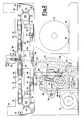
- Figure 1 shows a side elevation view of a packaging machine, wherein the film path with the relevant unwinding units, and the drive mechanisms driving the conveyor belts are shown;
- Figure 2 shows a magnified longitudinal sectional view of the machine of Figure 1 in its welding position;
- Figure 3 shows a magnified longitudinal sectional view equivalent to that of Figure 1, in a different operating position; and
- Figure 4 is a chart showing the combined motion of the welding unit and of the car.
- Referring to the drawings, a continuous packaging machine according to the present invention comprises a framework, generally indicated by the
reference numeral 11, on which a plurality of operating units - the transversal welding unit, the product conveyor units, the drive units, the unwinding units for unwinding the continuous wrapping material, and so forth - are installed, which are such as to make it possible individual products, or groups of products to be packaged in continuous, with said individual products/groups of products being indicated by thereference numeral 12, and having a size, both in height and in length, which may vary relatively to one another, and are fed after each other according to a whatever order, such as books, newpapers, magazines, bottles, containers, parcels, and the like. - As depicted in the figures, a wrapping or
packaging material 13, such as, e.g., a continuous heat-shrinking plastic film, is fed by a couple ofbobbins 14 respectively positioned on an upperunwinding unit 15 and on a lowerunwinding unit 16, fitted with compensatingmeans 17, such as so-said "dandy rolls", which make it possible thesame film 13 to be constantly and continuously, parallelly fed to a transversal welding unit, generally indicated by thereference number 18, which constrains it around theproduct 12, cutting it and welding it in correspondence of the leading edge and of the trailing edge of said product 12 (Figure 1). - The
product 12 is in fact fed in a known way by means of a conveyor belt (not shown in the figures) above afirst conveyor belt 19 installed upstream saidtransversal welding unit 18 and is subsequently made advance towards asecond conveyor belt 20 installed downstream saidtransversal welding unit 18. Both saidconveyor belts drive rolls 21, linked with each other by achain transmission 22, and driven by atransmission 23, also of chain-transmission type, driven by a main centralized motor-speed variator unit 24, which is suitable for supplying the movement to all the operating units of the packaging machine. - The
conveyor belts stationary return roll 25 fastened to theframework 11. At the ends of said sides of said "C"-shaped recess, twofurther rolls framework 11. In fact, theupper roll 26 is integrally rotatable relatively to acentral car 28, on which saidtransversal welding unit 18 is mounted, whilst thelower roll 27 is integrally rotatable relatively to a tighteningdevice 29, so designed as to link both saidlower rolls 27 of bothconveyor belts 19 and 20 (Figure 2). Such a tighteningdevice 29 connects the lower end of twochain portions 30 which, after running around twosprocket wheels 31 coaxially positioned relatively to thestationary rolls 25, are constrained to thecentral car 28, at the top thereof, nearly in correspondence of theupper rolls 26. - A plurality of
supports 32, constrained to thechain portions 30, bear an equal number ofrolls 33 constituting a roller apron on which upper portions of bothconveyor belts product 12 are fed. Thechain portions 30 slide on aflat guide 34 which is integral with theframework 11; also integral with theframework 11 is a furtherflat guide 35 on which the tighteningdevice 29 is guided by means ofrolls 36 integral with it. Theframework 11 furthermore supports furtherflat guides 37 on which support rolls 38 slide, which are integral, at the bottom, with thecentral car 28, so that also saidcentral car 28 can horizontally translate. - The
central car 28, which can horizontally reciprocate, is provided withshoulder portions 39, which extend upwards and through whichslots 40 are provided, inside which support rolls 41 slide, which support the opposite ends of anupper welding bar 42 vertically movable inside said slots, which, together with alower welding bar 43, stationary relatively to thecentral car 28, constitutes the above-saidtransversal welding unit 18. - Inside said
shoulder portions 39 and saidsame car 28, thefilm 13 is made run (Figure 1), according to a vertical direction parallel to the direction of movement of the welding bar of thetransversal welding unit 18. Said film is continuous, in that the film coming from the upper bobbin, and the film coming from the lower bobbin have been previously made integral with each other by means of a transversal welding. - More precisely, the
film 13 coming from theupper bobbin 14, once that it has left the upperunwinding unit 15, is guided by areturn roll 75 between theshoulder portions 39 of thecar 28 towards a calender 76 which drives the film being unwound from thelower bobbin 14 made revolve by the lowerunwinding unit 16 and positioned under theupper rolls 26, and it too on board of thecentral car 28, and made revolve by atransmission 78 integral with theupper roller 26 of thesecond conveyor belt 20. - The above said calender 76 acts as a means for guiding, driving and unwinding the
film 13, which comes from the lowerunwinding unit 16 and is deviated towards it byreturn rolls 77 integral with theframework 11 of the machine (Figure 1), and is engaged on the same film by means of actuator means 79, e.g., constituted by a cylinder, controlled by suitable sensor means which are disclosed in the following. - The
lower welding bar 43, which is positioned in the area of separation of the twoconveyor belts unwinding unit 15 and from the lower film-driving calender 76, to run through. - The horizontal reciprocating movement of the
central car 28, as well as the vertical movement of theupper welding bar 42 are determined in a purely mechanical way according to a certain law deriving from the particular structure given to a cam-crank and slotted link unit coupled with relevant levers which transmit the relevant motion to the upper welding bar, and to the welding unit supporting car, which furthermore makes it possible the upper, inner, mutually-opposite ends of both conveyor belts to be shifted. - In fact, exiting from said centralized motor-speed variator unit 24 (Figure 1), a
toothed belt 44 transmits the movement to a reduction gear 45, with the interposition of a brake-clutch unit 46. Furthermore, asmall transmission 47, e.g., a chain-type transmission, drives a mainintermediate shaft 48 to revolve, from the ends of said mainintermediate shaft 48 the revolutionary motion being taken, which drives acam 49 which controls the movement of theupper welding bar 42 and respectively the movement of a swinging crank and slottedlink 50 for the horizontal reciprocating of the central car 28 (Figure 2). - The main
intermediate shaft 48 is integral, at an end, with the center of a disk-cam 49′ which is provided with an eccentrically-positionedgroove 51; and at its other end, said mainintermediate shaft 48 is integral with an eccentric lever, i.e., acrank 52; with apin 54, which drives the swinging lever, i.e., the crank and slotted link, 50, being suitable for being radially positioned inside agroove 53 provided in saidcrank 52. The position of saidpin 54 inside thegroove 53 is adjustable relatively to said mainintermediate shaft 48. - Now, examining at first the drive of the
upper welding bar 42, one can observe that inside theeccentric groove 51 of the disk-cam 49 anidle roll 55 is inserted, which protrudes from an intermediate portion of aswinging lever 56, which is hinged, in correspondence of its lower end, in 57, and at its other end bears an articulated,adjustable lever 58. Said articulatedlever 58 is linked in its turn to adrive lever 59 keyed on areciprocating shaft 60 which bears, at its opposite ends, a couple oflevers 61 which drive the movement of theupper welding bar 42, and are linked to saidupper welding bar 42 by means of respective tie-rods 62, each of which incorporates a shock-absorber mechanism, not shown in the figures, in order to optimize the transversal welding of the wrappingfilm 13. - The
crank 52, installed at the other end of theintermediate shaft 48, by causing thepin 54 to rotate, causes the crank and slottedlink 50 to swing; with such crank and slottedlink 50 thecentral car 28 is articulatedly linked by means of an adjustable tie-rod 63, whichcentral car 28 being thus caused to reciprocate. The crank and slottedlink 50 is provided with agroove 80, inside which a runner orpad element 81, positioned on the end of saidpin 54, can slide. As said, thepin 54 can be shifted in an adjustable way inside thegroove 53, e.g., by means of anadjustment screw 64, so that the length of the stroke of thecentral car 28, or, better, the amplitude of its reciprocating movement, can be changed as desired, with varying lengths of the product to be packaged. In this way, by adequately adjusting the length of the stroke of thecar 28 which bears thewelding unit 18, the speed thereof can properly match the speed of the conveyor belts with varying product lengths. - The upper
unwinding unit 15 is driven by a kinematic transmission which draws the motion directly from the outlet end of the centralized motor-speed variator unit 24, with a speed reduction gear 65 and a brake-cluth unit 66 being interposed (Figure 1). - On the contrary, the lower
unwinding unit 16 draws its motion from a sprocket wheel 67, which interacts with thechain transmission 22 which drives thedriving rolls 21 of theconveyor belt 19 and of theconveyor belt 20. Said sprocket wheel 67 drives achain 68 which, with the interposition of acoupling 69, causes anunwinding roll 70 to revolve in order to unwind thelower bobbin 14, whenever necessary. - Together with these devices of essentially mechanical type, suitable sensor elements are provided in the machine, which control and correlate the various movements of the packaging machine, so as to cause it to perfectly and correctly operate, in particular acting on the movement of the main car, and on the movement of the upper welding bar, in order to achieve the purpose of the invention. For example, at the inlet side of the machine, a first set of photocells 71, vertically positioned on the
framework 11, is provided (Figure 1), which detect the arrival of the product, or of theproducts 12, defining the size in height thereof, and consequently presetting a time (relevant, e.g., to a "low", to a "medium" or to a "high" product), for the actuation of the upperunwinding unit 15. The welding cycle is then started by asecond photocell 72, which is preferably positioned on the same plane as of thefirst conveyor belt 19. In fact, said first conveyor belt is preferably composed by two conveyor belts placed side-by-side to, and spaced apart from, each other, wherein, in an area of separation thereof along their adjacent sides, an upwards-facing receiver element (not shown in the figures) for saidphotocell 72 is positioned. - A
third photocell 73 is also positioned in the area between said two side-by-side belts of thefirst conveyor belt 19, in the nearby of its end outlet portion and, once that it detects the arrival of the leading edge of the product, starts, by means of the intervention of the cylinder 79, the engagement of the drive calender 76 on thefilm 13, thus enabling theplastic film 13 to wrap on both the upper and lower sides the product made advance by theconveyor belts - Of course, the lower
unwinding unit 16 determines the unwinding of the film from thelower bobbin 14 when the relevant compensator means 17 command thecoupling 69 to engage, so as to make theunwinding roll 70 revolve. - Finally, a
fourth photocell 74 can be furthermore and optionally provided, which is positioned beyond the area of separation between the twoconveyor belts second belt 20 and above it on theframework 11, which, by detecting the trailing edge of the passed and packaged product, controls the perfect prosecution of machine's operation and allows sich prosecution. The provision of said sensor elements or photocells allows the operation of the packaging machine according to the present invention to be easily understood. - In fact, as hereinabove said, a conveyor means feeds the products after each other towards the packaging machine and said feed is initialy detected by the first set of photocells 71 at the inlet end of the
first conveyor belt 19. Thereafter, the product continues to advance on board of theconveyor belt 19, until the passage thereof in correspondence of thesecond photocell 72 confirms the feed, and thethird photocell 73 commands the drive calender 76 to reach its engagement position, with the lowerunwinding unit 16 being started, if necessary, thus enabling thefilm 13 to wrap the product both at the top and at the bottom, in that the film coming from the upper bobbin of the upperunwinding unit 15 is bonded to the film coming from the upper unwinding unit, by means of a transversal welding previously carried out. When thesecond photocell 72 detects the trailing end of theproduct 12, said detection starts the cycle of welding-central car shifting by means of the brake-clutch unit 46 which, by getting engaged, enables the motion to be transmitted. Of course, when also thethird photocell 73, detects the trailing edge of theproduct 12, it disengages the drive calender 76 and causes the lowerunwinding unit 16 to stop, so that, after that the welding and the cutting of the film have been simultaneously carried out, said film positions again itself in a nearly vertical position inside thecar 28, nearly parallel to the direction of movement of the welding unit, ready to receive a new product. - The engagement of the brake-clutch unit 46 makes the disk-
cam 49 revolve, in order to actuate theupper welding bar 42, and makes the crank and slottedlink 50 start to swing, which causes thecentral car 28 to reciprocate. - In Figure 4, the combined movement which derives from the above is depicted; one can observe that the (A) step of approaching of the welding bar towards its position of engagement with the material to be packaged, the (C) step of removal, and the (D) step of car return are rather fast, whilst the (B) step of accompanying during the welding step is slower. By the "O" character, the point relevant to the stand-by position, at which the welding cycle starts, is indicated, and in chain a portion of the film-wrapped product is also indicated, wherein the minimizing in wrapping film consumption can be observed.
- It should be observed that the (A) step, and the (C) step, respectively of approaching and of removal of the welding bar, take place on a nearly vertical direction, with the welding unit travelling in the same direction of advancement as of the conveyor belts, still in order to minimize the consumption of the packaging film. According to a generic and exemplifying formulation, the whole cycle could be subdivided, as regards the total revolution angle, into three angles of approximately 100° each, for the first three (A), (C) and (D) steps, and an angle of 60° as regards the last (B) step, of accompanying during the welding step. The combination of the movements of said cam and of said swinging crank and slotted link makes it possible a combined movement to be obtained, which is determined in a completely mechanical way, essentially comprising a step of approaching of the welding bar towards said products wrapped inside said packaging material, an accompanying step during the welding step, a removal step, and a step of quick return to the stand-by position, and representable by means of an upside-down isosceles trapezium with inclined, curved sides.
- The important point is that during the (B) step of accompanying during the welding step, the
central car 28 horizontally moves in such a way that its motion, causing a change in length of both portions ofconveyor belts rollers 33 which constitute the so-said roller apron, makes it possible the own movement of thebelts transversal welding unit 18 remains closed for the necessary time for a correct welding of the wrapping film to be obtained. This is the so-said "slow step" of the welding cycle. The movement of theconveyor belts car 28, by being integral with it, whilst thelower rollers 27 are made integral with the tighteningdevice 29 and with thechain portions 30, and exactly move in the opposite direction to the direction of displacement of theupper roll 26 positioned on the same side, and nearly at the end of thesame chain portion 30. - In fact, one could consider that the two
chain portions 30, the tighteningdevice 29 and the lower body of thecentral car 28 constitute a closed loop which can move around both idle,coaxial sprocket wheels 31, free of rotating relatively to thestationary rolls 25, revolutionary and integral with theframework 11. In this way, inasmuch as the upper,movable welding bar 42, positioned in a nearly bridge-fashion on the upwards extendingshoulder portions 39, is driven by a cam-driven movement, and inasmuch as with this movement the movement is combined of thecar 28 which supports the welding unit, driven by a swinging crank and slotted link, a combined movement of sinking of the welding bar, and of accompanying of the product with the car during the welding step, derives, which, by realizing the transversal welding precisely in the nearby of the product, makes it possible a saving in the amount of the plastic material used for the packaging to be obtained, with an as small amount thereof as possible being consumed. Precisely the arrangement of the welding bar in a bridge-position, the possibility of actuating the cycle of welding at the trailing edge of the product, and the detection of the height of the product being packaged make it possible the above-said optimization in packaging film consumption to be achieved, independently from the height of the product, or of the products to be packaged, with any stop times being got rid of. - Advantageously, it should be observed that in a machine according to the present invention, inasmuch as the
transversal welding unit 18 can be turned on at the end of thesame product 12 by means of the intervention of thephotocell 72, products of any lengths can be packaged.
Claims (12)
Priority Applications (1)
| Application Number | Priority Date | Filing Date | Title |
|---|---|---|---|
| AT88201608T ATE96389T1 (en) | 1987-08-27 | 1988-07-26 | PACKAGING MACHINE FOR CONTINUOUS PACKAGING OF PRODUCTS WITH CHANGING HEIGHTS. |
Applications Claiming Priority (2)
| Application Number | Priority Date | Filing Date | Title |
|---|---|---|---|
| IT2173287 | 1987-08-27 | ||
| IT21732/87A IT1222550B (en) | 1987-08-27 | 1987-08-27 | CONTINUOUS PACKAGING MACHINES FOR VARIABLE SIZE PRODUCTS |
Publications (3)
| Publication Number | Publication Date |
|---|---|
| EP0304979A2 true EP0304979A2 (en) | 1989-03-01 |
| EP0304979A3 EP0304979A3 (en) | 1990-02-07 |
| EP0304979B1 EP0304979B1 (en) | 1993-10-27 |
Family
ID=11186084
Family Applications (1)
| Application Number | Title | Priority Date | Filing Date |
|---|---|---|---|
| EP88201608A Expired - Lifetime EP0304979B1 (en) | 1987-08-27 | 1988-07-26 | Packaging machine for the continuous packaging of products having a variable size |
Country Status (8)
| Country | Link |
|---|---|
| US (1) | US4881357A (en) |
| EP (1) | EP0304979B1 (en) |
| JP (1) | JP2777145B2 (en) |
| AT (1) | ATE96389T1 (en) |
| CA (1) | CA1296245C (en) |
| DE (1) | DE3885209T2 (en) |
| ES (1) | ES2045087T3 (en) |
| IT (1) | IT1222550B (en) |
Cited By (9)
| Publication number | Priority date | Publication date | Assignee | Title |
|---|---|---|---|---|
| DE4010506A1 (en) * | 1989-04-04 | 1990-10-11 | Ulma S Coop | Containers sealed closing machine |
| ES2065215A2 (en) * | 1991-07-29 | 1995-02-01 | Baumer Srl | Machine for the packaging of articles of any size in sheets of, in particular, a heat-shrinking material |
| ES2122867A1 (en) * | 1995-05-12 | 1998-12-16 | Construcciones Metalicas J Bar | Automatic packaging unit using shrink film wrap |
| DE10241802A1 (en) * | 2002-09-06 | 2004-03-18 | Convenience Food Systems Wallau Gmbh & Co Kg | Packing machine with one travel unit |
| WO2012045553A1 (en) * | 2010-10-07 | 2012-04-12 | Hochland Se | Belt conveyor having a variable-length belt support |
| CN104494880A (en) * | 2014-12-22 | 2015-04-08 | 常熟市鹏龙机械有限公司 | PE (polyethylene) film packaging machine |
| ITUB20160599A1 (en) * | 2016-02-09 | 2017-08-09 | Colines Spa | METHOD AND CUTTING UNIT IN AN EXTENSIBLE FILM PACKAGING MACHINE |
| WO2017137318A1 (en) * | 2016-02-09 | 2017-08-17 | Colines S.P.A. | Packaging method and machine in extensible film of products fed in continuous |
| WO2017137360A1 (en) * | 2016-02-09 | 2017-08-17 | Colines S.P.A. | Packaging method and machine in extensible film of products fed in groups |
Families Citing this family (8)
| Publication number | Priority date | Publication date | Assignee | Title |
|---|---|---|---|---|
| JP3245746B2 (en) * | 1989-12-08 | 2002-01-15 | エス イー ゲー シュバイツェリッシェ インズストリー‐ゲゼルシャフト | Column forming device for articles, especially chocolate bars |
| IT1244384B (en) * | 1990-11-05 | 1994-07-11 | Mopa | LUNG FOR THE ACCUMULATION AND LIBERATION IN EQUIDISTANT ROWS OR WITH A PROGRAMMED CADENCE OF PRODUCTS COMING FROM A CONTINUOUS ADVANCE LINE ARRANGED IN NON-EQUIDISTANT RANGES. |
| US5566531A (en) * | 1992-07-15 | 1996-10-22 | John E. Nordstrom | Napkin wrapping machine and method for wrapping napkins |
| IT1272536B (en) * | 1993-08-30 | 1997-06-23 | Ocme Srl | CARTONING MACHINE FOR WRAPPING CARTONS AROUND HIGH SPEED OBJECTS |
| EP1398289B1 (en) * | 2002-09-13 | 2008-06-11 | Müller Martini Holding AG | Transport system for processing printed products |
| PT1502883E (en) * | 2003-08-01 | 2008-07-09 | Will E C H Gmbh & Co | Device for the transverse conveying of reams |
| US20060218884A1 (en) * | 2005-03-30 | 2006-10-05 | Sealed Air Corporation | Adjustable infeed bed for packaging apparatus |
| ITMI20131550A1 (en) * | 2013-09-20 | 2015-03-21 | Area S R L | EQUIPMENT FOR PACKAGING BOTTLES WITH THIN PLASTIC EXTENSIBLE MATERIALS. |
Citations (3)
| Publication number | Priority date | Publication date | Assignee | Title |
|---|---|---|---|---|
| US3618740A (en) * | 1969-08-26 | 1971-11-09 | Ferag Ag | Apparatus for transporting and working piece goods and the like |
| FR2297773A1 (en) * | 1975-01-17 | 1976-08-13 | Situno Holding Sa | WELDING AND CUTTING DEVICE FOR PACKAGING MACHINES |
| GB2024760A (en) * | 1978-06-13 | 1980-01-16 | Sitma Spa | Web feeding in a packaging machine |
Family Cites Families (2)
| Publication number | Priority date | Publication date | Assignee | Title |
|---|---|---|---|---|
| DE2949519C2 (en) * | 1979-12-08 | 1985-08-22 | Hans Hugo 4020 Mettmann Büttner | Machine for strapping packages |
| JPS57133829A (en) * | 1981-02-06 | 1982-08-18 | Shin Meiwa Ind Co Ltd | High speed packer |
-
1987
- 1987-08-27 IT IT21732/87A patent/IT1222550B/en active
-
1988
- 1988-07-25 US US07/223,915 patent/US4881357A/en not_active Expired - Lifetime
- 1988-07-26 EP EP88201608A patent/EP0304979B1/en not_active Expired - Lifetime
- 1988-07-26 AT AT88201608T patent/ATE96389T1/en not_active IP Right Cessation
- 1988-07-26 ES ES88201608T patent/ES2045087T3/en not_active Expired - Lifetime
- 1988-07-26 DE DE88201608T patent/DE3885209T2/en not_active Expired - Fee Related
- 1988-08-12 CA CA000574623A patent/CA1296245C/en not_active Expired - Lifetime
- 1988-08-25 JP JP63211569A patent/JP2777145B2/en not_active Expired - Lifetime
Patent Citations (3)
| Publication number | Priority date | Publication date | Assignee | Title |
|---|---|---|---|---|
| US3618740A (en) * | 1969-08-26 | 1971-11-09 | Ferag Ag | Apparatus for transporting and working piece goods and the like |
| FR2297773A1 (en) * | 1975-01-17 | 1976-08-13 | Situno Holding Sa | WELDING AND CUTTING DEVICE FOR PACKAGING MACHINES |
| GB2024760A (en) * | 1978-06-13 | 1980-01-16 | Sitma Spa | Web feeding in a packaging machine |
Cited By (15)
| Publication number | Priority date | Publication date | Assignee | Title |
|---|---|---|---|---|
| DE4010506A1 (en) * | 1989-04-04 | 1990-10-11 | Ulma S Coop | Containers sealed closing machine |
| ES2065215A2 (en) * | 1991-07-29 | 1995-02-01 | Baumer Srl | Machine for the packaging of articles of any size in sheets of, in particular, a heat-shrinking material |
| ES2122867A1 (en) * | 1995-05-12 | 1998-12-16 | Construcciones Metalicas J Bar | Automatic packaging unit using shrink film wrap |
| DE10241802A1 (en) * | 2002-09-06 | 2004-03-18 | Convenience Food Systems Wallau Gmbh & Co Kg | Packing machine with one travel unit |
| WO2012045553A1 (en) * | 2010-10-07 | 2012-04-12 | Hochland Se | Belt conveyor having a variable-length belt support |
| CN104494880A (en) * | 2014-12-22 | 2015-04-08 | 常熟市鹏龙机械有限公司 | PE (polyethylene) film packaging machine |
| ITUB20160599A1 (en) * | 2016-02-09 | 2017-08-09 | Colines Spa | METHOD AND CUTTING UNIT IN AN EXTENSIBLE FILM PACKAGING MACHINE |
| WO2017137318A1 (en) * | 2016-02-09 | 2017-08-17 | Colines S.P.A. | Packaging method and machine in extensible film of products fed in continuous |
| WO2017137403A1 (en) * | 2016-02-09 | 2017-08-17 | Colines S.P.A. | Cutting method and unit in a packaging machine in extensible film |
| WO2017137360A1 (en) * | 2016-02-09 | 2017-08-17 | Colines S.P.A. | Packaging method and machine in extensible film of products fed in groups |
| CN108698718A (en) * | 2016-02-09 | 2018-10-23 | 科林斯股份公司 | Packing method and machine for the extensible film for feeding product in groups |
| RU2725840C2 (en) * | 2016-02-09 | 2020-07-06 | Колинес С.п.А. | Method and machine for packaging products into stretchable film, supplied by blocks |
| RU2725845C2 (en) * | 2016-02-09 | 2020-07-06 | Колинес С.п.А. | Cutting method and cutting unit in machine for articles packing into stretchable film |
| US10934043B2 (en) | 2016-02-09 | 2021-03-02 | Colines S.P.A. | Cutting method and unit in a packaging machine in extensible film |
| US11117693B2 (en) | 2016-02-09 | 2021-09-14 | Colines S.P.A. | Packaging method and machine in extensible film of products fed in continuous |
Also Published As
| Publication number | Publication date |
|---|---|
| DE3885209T2 (en) | 1994-04-14 |
| ES2045087T3 (en) | 1994-01-16 |
| DE3885209D1 (en) | 1993-12-02 |
| IT1222550B (en) | 1990-09-05 |
| ATE96389T1 (en) | 1993-11-15 |
| CA1296245C (en) | 1992-02-25 |
| IT8721732A0 (en) | 1987-08-27 |
| EP0304979B1 (en) | 1993-10-27 |
| EP0304979A3 (en) | 1990-02-07 |
| US4881357A (en) | 1989-11-21 |
| JPS6470312A (en) | 1989-03-15 |
| JP2777145B2 (en) | 1998-07-16 |
Similar Documents
| Publication | Publication Date | Title |
|---|---|---|
| US4881357A (en) | Packaging machine for the continuous packaging of products having a variable size | |
| EP0304978B1 (en) | Packaging machine for the continuous packaging of individual products, and of groups of overlapped products having a variable height | |
| US5475965A (en) | Machine for sealing containers by applying a covering film | |
| US7114609B2 (en) | Product diverter and method | |
| US6067780A (en) | Automatic packaging machine for packaging products | |
| JP3868490B2 (en) | Multi-pack packaging equipment | |
| US4029194A (en) | Automatic indexing and transferring apparatus | |
| EP2001772B1 (en) | Device for forming a continuous flow of oriented products | |
| US5285621A (en) | Apparatus for stretching a continuous plastics film in a packaging machine | |
| JPS5843292B2 (en) | Kamitaba Mataha Sonorujibutsunoratsupingouchi | |
| EP1043250B1 (en) | An ordering device for arranging products received in a loose state in an orderly succession | |
| CA1190780A (en) | Method and apparatus for making bag-type packages | |
| EP1500592B1 (en) | Apparatus for wrapping groups of products | |
| CN209921738U (en) | Non-woven fabrics packing closing device | |
| US4058426A (en) | Method and apparatus for wrapping objects with a sealable wrap | |
| EP0865988A1 (en) | A device for stacking sorted products to be packaged | |
| EP2853498B1 (en) | Machine and method for packaging articles | |
| EP1003675B1 (en) | Transfer mechanism | |
| CN218142455U (en) | Self-adaptation bag transport mechanism | |
| EP0270880A1 (en) | Sealing and cutting apparatus for continuous automatic wrapping machines | |
| KR200290503Y1 (en) | A film packing machine | |
| CN115504017A (en) | Self-adaptation bag transport mechanism | |
| KR20040003243A (en) | A film packing machine |
Legal Events
| Date | Code | Title | Description |
|---|---|---|---|
| PUAI | Public reference made under article 153(3) epc to a published international application that has entered the european phase |
Free format text: ORIGINAL CODE: 0009012 |
|
| AK | Designated contracting states |
Kind code of ref document: A2 Designated state(s): AT BE CH DE ES FR GB GR IT LI LU NL SE |
|
| PUAL | Search report despatched |
Free format text: ORIGINAL CODE: 0009013 |
|
| AK | Designated contracting states |
Kind code of ref document: A3 Designated state(s): AT BE CH DE ES FR GB GR IT LI LU NL SE |
|
| RAP1 | Party data changed (applicant data changed or rights of an application transferred) |
Owner name: SITMA S.P.A. |
|
| 17P | Request for examination filed |
Effective date: 19900628 |
|
| 17Q | First examination report despatched |
Effective date: 19920227 |
|
| GRAA | (expected) grant |
Free format text: ORIGINAL CODE: 0009210 |
|
| ITF | It: translation for a ep patent filed |
Owner name: BARZANO' E ZANARDO MILA |
|
| AK | Designated contracting states |
Kind code of ref document: B1 Designated state(s): AT BE CH DE ES FR GB GR IT LI LU NL SE |
|
| REF | Corresponds to: |
Ref document number: 96389 Country of ref document: AT Date of ref document: 19931115 Kind code of ref document: T |
|
| REF | Corresponds to: |
Ref document number: 3885209 Country of ref document: DE Date of ref document: 19931202 |
|
| ET | Fr: translation filed | ||
| REG | Reference to a national code |
Ref country code: GR Ref legal event code: FG4A Free format text: 3009542 |
|
| REG | Reference to a national code |
Ref country code: ES Ref legal event code: FG2A Ref document number: 2045087 Country of ref document: ES Kind code of ref document: T3 |
|
| PLBE | No opposition filed within time limit |
Free format text: ORIGINAL CODE: 0009261 |
|
| STAA | Information on the status of an ep patent application or granted ep patent |
Free format text: STATUS: NO OPPOSITION FILED WITHIN TIME LIMIT |
|
| EPTA | Lu: last paid annual fee | ||
| 26N | No opposition filed | ||
| EAL | Se: european patent in force in sweden |
Ref document number: 88201608.2 |
|
| REG | Reference to a national code |
Ref country code: GB Ref legal event code: IF02 |
|
| PGFP | Annual fee paid to national office [announced via postgrant information from national office to epo] |
Ref country code: ES Payment date: 20050818 Year of fee payment: 18 |
|
| PGFP | Annual fee paid to national office [announced via postgrant information from national office to epo] |
Ref country code: GR Payment date: 20060616 Year of fee payment: 19 |
|
| PGFP | Annual fee paid to national office [announced via postgrant information from national office to epo] |
Ref country code: AT Payment date: 20060712 Year of fee payment: 19 |
|
| PGFP | Annual fee paid to national office [announced via postgrant information from national office to epo] |
Ref country code: FR Payment date: 20060719 Year of fee payment: 19 |
|
| PGFP | Annual fee paid to national office [announced via postgrant information from national office to epo] |
Ref country code: DE Payment date: 20060720 Year of fee payment: 19 |
|
| PGFP | Annual fee paid to national office [announced via postgrant information from national office to epo] |
Ref country code: CH Payment date: 20060727 Year of fee payment: 19 |
|
| PGFP | Annual fee paid to national office [announced via postgrant information from national office to epo] |
Ref country code: LU Payment date: 20060728 Year of fee payment: 19 |
|
| PGFP | Annual fee paid to national office [announced via postgrant information from national office to epo] |
Ref country code: BE Payment date: 20060911 Year of fee payment: 19 |
|
| PGFP | Annual fee paid to national office [announced via postgrant information from national office to epo] |
Ref country code: GB Payment date: 20070725 Year of fee payment: 20 |
|
| BERE | Be: lapsed |
Owner name: *SITMA S.P.A. Effective date: 20070731 |
|
| PGFP | Annual fee paid to national office [announced via postgrant information from national office to epo] |
Ref country code: NL Payment date: 20070624 Year of fee payment: 20 Ref country code: IT Payment date: 20070726 Year of fee payment: 20 |
|
| REG | Reference to a national code |
Ref country code: CH Ref legal event code: PL |
|
| EUG | Se: european patent has lapsed | ||
| PG25 | Lapsed in a contracting state [announced via postgrant information from national office to epo] |
Ref country code: CH Free format text: LAPSE BECAUSE OF NON-PAYMENT OF DUE FEES Effective date: 20070731 Ref country code: SE Free format text: LAPSE BECAUSE OF NON-PAYMENT OF DUE FEES Effective date: 20070727 Ref country code: DE Free format text: LAPSE BECAUSE OF NON-PAYMENT OF DUE FEES Effective date: 20080201 Ref country code: LI Free format text: LAPSE BECAUSE OF NON-PAYMENT OF DUE FEES Effective date: 20070731 |
|
| REG | Reference to a national code |
Ref country code: FR Ref legal event code: ST Effective date: 20080331 |
|
| PG25 | Lapsed in a contracting state [announced via postgrant information from national office to epo] |
Ref country code: AT Free format text: LAPSE BECAUSE OF NON-PAYMENT OF DUE FEES Effective date: 20070726 |
|
| PGFP | Annual fee paid to national office [announced via postgrant information from national office to epo] |
Ref country code: SE Payment date: 20060705 Year of fee payment: 19 |
|
| REG | Reference to a national code |
Ref country code: GB Ref legal event code: PE20 Expiry date: 20080725 |
|
| PG25 | Lapsed in a contracting state [announced via postgrant information from national office to epo] |
Ref country code: BE Free format text: LAPSE BECAUSE OF NON-PAYMENT OF DUE FEES Effective date: 20070731 |
|
| PG25 | Lapsed in a contracting state [announced via postgrant information from national office to epo] |
Ref country code: FR Free format text: LAPSE BECAUSE OF NON-PAYMENT OF DUE FEES Effective date: 20070731 |
|
| NLV7 | Nl: ceased due to reaching the maximum lifetime of a patent |
Effective date: 20080726 |
|
| REG | Reference to a national code |
Ref country code: ES Ref legal event code: FD2A Effective date: 20070727 |
|
| PG25 | Lapsed in a contracting state [announced via postgrant information from national office to epo] |
Ref country code: NL Free format text: LAPSE BECAUSE OF EXPIRATION OF PROTECTION Effective date: 20080726 |
|
| PG25 | Lapsed in a contracting state [announced via postgrant information from national office to epo] |
Ref country code: GB Free format text: LAPSE BECAUSE OF EXPIRATION OF PROTECTION Effective date: 20080725 |
|
| PG25 | Lapsed in a contracting state [announced via postgrant information from national office to epo] |
Ref country code: GR Free format text: LAPSE BECAUSE OF NON-PAYMENT OF DUE FEES Effective date: 20080206 Ref country code: ES Free format text: LAPSE BECAUSE OF NON-PAYMENT OF DUE FEES Effective date: 20070727 |
|
| PG25 | Lapsed in a contracting state [announced via postgrant information from national office to epo] |
Ref country code: LU Free format text: LAPSE BECAUSE OF NON-PAYMENT OF DUE FEES Effective date: 20070726 |