EP0304237B1 - Connector element - Google Patents
Connector element Download PDFInfo
- Publication number
- EP0304237B1 EP0304237B1 EP88307475A EP88307475A EP0304237B1 EP 0304237 B1 EP0304237 B1 EP 0304237B1 EP 88307475 A EP88307475 A EP 88307475A EP 88307475 A EP88307475 A EP 88307475A EP 0304237 B1 EP0304237 B1 EP 0304237B1
- Authority
- EP
- European Patent Office
- Prior art keywords
- shaft
- sleeve
- connector element
- elongate member
- end region
- Prior art date
- Legal status (The legal status is an assumption and is not a legal conclusion. Google has not performed a legal analysis and makes no representation as to the accuracy of the status listed.)
- Expired - Lifetime
Links
- 230000004323 axial length Effects 0.000 claims description 2
- 230000000694 effects Effects 0.000 abstract description 5
- 230000013011 mating Effects 0.000 description 4
- 238000000605 extraction Methods 0.000 description 1
- 238000004519 manufacturing process Methods 0.000 description 1
Images


Classifications
-
- H—ELECTRICITY
- H05—ELECTRIC TECHNIQUES NOT OTHERWISE PROVIDED FOR
- H05K—PRINTED CIRCUITS; CASINGS OR CONSTRUCTIONAL DETAILS OF ELECTRIC APPARATUS; MANUFACTURE OF ASSEMBLAGES OF ELECTRICAL COMPONENTS
- H05K7/00—Constructional details common to different types of electric apparatus
- H05K7/14—Mounting supporting structure in casing or on frame or rack
- H05K7/1401—Mounting supporting structure in casing or on frame or rack comprising clamping or extracting means
- H05K7/1411—Mounting supporting structure in casing or on frame or rack comprising clamping or extracting means for securing or extracting box-type drawers
- H05K7/1412—Mounting supporting structure in casing or on frame or rack comprising clamping or extracting means for securing or extracting box-type drawers hold down mechanisms, e.g. avionic racks
-
- Y—GENERAL TAGGING OF NEW TECHNOLOGICAL DEVELOPMENTS; GENERAL TAGGING OF CROSS-SECTIONAL TECHNOLOGIES SPANNING OVER SEVERAL SECTIONS OF THE IPC; TECHNICAL SUBJECTS COVERED BY FORMER USPC CROSS-REFERENCE ART COLLECTIONS [XRACs] AND DIGESTS
- Y10—TECHNICAL SUBJECTS COVERED BY FORMER USPC
- Y10S—TECHNICAL SUBJECTS COVERED BY FORMER USPC CROSS-REFERENCE ART COLLECTIONS [XRACs] AND DIGESTS
- Y10S411/00—Expanded, threaded, driven, headed, tool-deformed, or locked-threaded fastener
- Y10S411/916—Bolt having tension feature
Definitions
- This invention relates to a connector element.
- the connector element described herein has particular application for connecting two components in a system which is likely to be subject to vibration.
- a connector element for use in connecting together two components, the components having respective surfaces, which, when the components are connected together, abut one another, the connector element comprising:
- such predetermined relative positions can be indicative that two components just abut.
- the connector element can include a rotatable grip remote from said threaded end region of the shaft and coupled to the shaft so that rotation of said grip causes rotation of said shaft, said end region of the elongate member extending axially of the grip.
- the grip includes means providing a surface having a recessed portion, for example of dished shape, and the indicating means comprises a resilient planar indicating element secured to said end region of the elongate member.
- the grip includes means providing a surface having a slot
- the indication means comprises a further elongate member (indicator lever) pivotally mounted to said end region of the first-mentioned elongate member.
- the arrangement is such that the connector element operates as follows: when the connector element is not in use the sleeve is urged by the biasing means in the direction away from the radial flange on the shaft, thereby causing the elongate member to adopt a first position in which part of the indicating element protrudes above the surface of the grip to indicate that the components are not correctly relatively positioned.
- the resilient planar indicating element sits in the recessed portion of the grip, whereby the shape of the indicator element is deformed so that its edges protrude above the grip surface.
- the indicator lever is pivoted so that its end protrudes from the slot.
- the indicating element When the connector element is in use to connect together two such components, the indicating element will remain in that first position until the predetermined relative positions of the sleeve and shaft have been reached, when the sleeve causes the indicating element to move against the action of the biasing means towards the radial flange of the shaft thereby urging the elongate member towards the second position in which the indicating element lies flush against the grip surface, thereby indicating that the components are correctly relatively positioned.
- the resilient planar indicating element is released from the recessed portion so that it lies flush against the grip surface.
- the indicator lever lies within the slot.
- the shaft is formed with a slot in which slides a bar which is secured to the sleeve to extend diametrically thereof and which is fixedly secured to the first-mentioned elongate member.
- the grip incorporates a torque limiting device for limiting the torque applied to the shaft after two components have been correctly relatively positioned, as indicated by the indicating means.
- torque limited bolt Since the connector element of the preferred embodiment of the present invention incorporates a torque limiting device, it will be referred to hereinafter as torque limited bolt.
- the connector element described hereinafter can ensure that two components just abut when the connector element is done up and is resistant to vibration so that it will not inadvertently come undone while in use.
- the connector element should be able to be positively locked against undoing itself under the influence of vibration.
- the connector element should preferably not exert a force greater than is required just to ensure that the components abut.
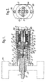
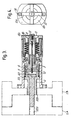
- FIG. 1 Reference is made to Figures 1 to 4. It is noted that reference numerals present in Figures 1 and 2 are not generally duplicated in Figures 3 and 4. This is for reasons of clarity.
- the purpose of the bolt is to ensure that two mating components 2A and 2B are fixedly relatively secured in a vibration proof manner.
- the bolt is permanently in place relative to the mating component 2B shown in Figure 1 and 2, and when component 2A is brought into contact with the component 2B the bolt is done up until the components just mate, whereafter a predetermined torque is applied to maintain a secure connection.
- the bolt comprises a shaft 1 screw threaded at one end 1a to engage a correspondingly screw threaded hole 30 in one 2A of the two mating components 2A, 2B.
- the shaft 1 is formed with a portion 31 of larger diameter than that of the end 1a, this portion 31 of larger diameter having a slot 5 formed therein.
- the shaft 1 also has a radial flange 35 and on one side of this flange 35 (to the right in Figure 1) a smaller diameter portion 36 extending within a sleeve 17.
- the smaller diameter portion 36 is fixedly secured to the sleeve 17 to rotate therewith. It is possible however to replace one shaft by another to accommodate different sized shafts.
- the shaft 1 has a passageway 32 formed therein for receiving a rod 8 of an indicating mechanism to be described in more detail hereinafter.
- a cylindrical casing 3 has a flange 37 to be secured to the component 2B by means of holes 38 in combination with screws or other suitable securing elements.
- the casing 3 can be formed as part of the component 2B.
- the casing 3 enables the bolt to be left permanently in place relative to component 2B, the shaft 1 passing through a hole 30B in the component 2B aligned with the threaded hole 30A.
- the casing 3 has a front wall 39 provided with an aperture 40 for receiving the sleeve 17.
- a thrust washer 13 for extraction is provided between the flange 35 of the shaft and the front wall 39 of the casing 3.
- the casing 3 also carries an axially extending cylindrical portion 41, having serrated teeth 6 the purpose of which is described in more detail hereinafter.
- a rotatable grip 42 is fitted about the sleeve 17, the grip 42 comprising an external collar 15 and a knob 44.
- the knob 44 carries a colour coded elastomeric cylinder 16.
- the colour coding is indicative of the maximum torque which can be applied by the bolt.
- the collar 15 can slide but not rotate relative to the knob 44.
- the elastomeric cylinder 16 has four circumferentially spaced protrusions 50 which provide a biasing force against a recessed surface 51 of the collar 15.
- the collar 15 is castellated so as to co-operate with respective ridges in the collar 15 to provide resistance to turning the knob 16. This assists in preventing vibrational effects from undoing the bolt once secured.
- the knob 44 has, at its right hand end as seen in Figure 1, a recess in which are disposed a pack of disc springs, (for example Belleville washers) 45.
- the springs are held in position by an adjustable nut 18.
- the adjustable nut 18 has in its surface 18b a recessed or dished portion 18a the purpose of which will be described hereinafter.
- the axially extending portion 41 of the casing 3 forms an annular recess which co-operates with the collar 15 of rotatable grip 42 and the sleeve 17 to define an annular cavity housing a torque limiting arrangement 47.
- the torque limiting arrangement is as described in European Patent Application No. 83305061.0 (Publication No. 0105609) and comprises a drive plate 48 and a plurality of ball bearings 49. Operation of the arrangement is described in detail in EPA 0105609 and will hence not be described in more detail hereinafter.
- the collar 15 is removably secured to the axially extending portion 41 of the casing 3 via a positive self locking rachet mechanism.
- the rachet mechanism comprises the set of "saw teeth" 6 on the axially extending portion 41 co-operating with a set of similar teeth 14 on the collar 15.
- the saw teeth are so shaped (see Figure 6) that the leading edge has a smaller gradient than the trailing edge whereby rotation of the collar 15 of the grip 42 in one direction is permitted (the direction which cause the bolt to be tightened), against resistance caused by the action of the trailing surface of a tooth on the collar 15 sliding "up and over" the leading surface of a tooth on the axially extending portion 41.
- the mechanism includes a sleeve or collar 11 encircling the shaft 1 between the latter and the hole 30B and a T-piece 12 located in apertures in the collar 11 and assembled onto one end of the rod 8 so as to be slidable (with axial movement of the rod 8) along the slot 5.
- the T-piece 12 is secured to the rod 8 by screwing. In this way, the operable length of the rod 8 can be adjusted as described later.
- the collar 11 has a flange 53 between which and the flange 35 of the shaft 1 is arranged a coil spring 4.
- a rod guide 9 which is screw threadedly secured to the rod 8. While it might be simplest to manufacture the push rod 8 with a screw thread along its entire length, a screw thread is only required at the one end where it is connected to the T-piece 12 and at the other end where it is connected to the guide 9.
- An adjusting screw 19 serves to attach an indicator spring 10 to the guide 9.
- the indicator spring 10 can take the form of a planar resilient member such as a flat flexible member of cruciform shape (as illustrated) or an elastomeric disc. It will be apparent from the following description that other resilient members could be used, but the afore-mentioned forms have been found to be preferred.
- the adjusting screw 19 can adjust the position of the rod 8 longitudinally relative to the passageway 32. In this way, the bolt can be set up by positioning the collar 11 flush with the face of connector 2B and then adjusting the adjusting screw 19 until the indicator spring 10 lies flat against the facing surface 18b of the nut 18, as shown in Figure 3. To accommodate this adjustment, a recess 60 is provided in the shaft 1.
- the coil spring 4 overcomes the force exerted by the indicator spring 10 to pull the latter into the dished portion 18a of the adjusting nut 18, forcing the tags 10a of the cruciform spring 10 (or the periphery of an elastomeric disc) to protrude from the nut 18 to indicate the unmated condition of the connector.
- the knob 44 is rotated to draw the two connectors 2A, 2B together.
- the serrated teeth 6 of which are allowed to ride over the serrated teeth 14 of the casing 3 against the pressure exerted by the circumferentially spaced protrusions of the elastomeric cylinder 16.
- the collar 11 is pushed back against the force of the spring 4 which causes the T-piece 12 and hence the push rod 8 and guide 9 to be moved axially so as to permit the indicator spring 10 to resume its flat condition flush with the surface 18b of the nut 18 as shown in Figure 3.
- the knob 44 is further rotated until the torque limit is reached [as described in the above-referenced European patent application] after which the torque limiting mechanism 47 will slip and the shaft 1 will no longer be driven.
- An adjustable nut 180 replaces the adjustable nut 18 of the first described embodiment.
- the adjustable nut 180 has a slot formed in its surface.
- Indicator lever 110 is located within the slot 112 by a pivot pin 114.
- a push rod 116 may be connected to the end of the rod 8.
- the end of the push rod 116 is attached to the indicator lever by means of a further pivot pin 118.
- the proximity of pivot points 114 and 118 serves to amplify the movement of lever 110 in response to movement of push rod 116.
- the width of the indicator lever is less than the diameter of the push rod 116 in order that the indicator lever can be held axially with the push rod and both items screwed onto the rod 8.
- the bolt can be set up by positioning the collar 11 flush with the face of the connector 2b and screwing the push rod complete with the indicator lever assembled on the pivot pin 118 until the indicator lever can be positioned at 90° relative to the push rod 116, so that it lies flush within the slot adjusting nut 180 as shown in Figure 8.
- Indicating mechanism operates substantially as described above. That is, the coil spring 4 pulls the end of the indicator lever secured to the push rod 116 thereby causing the opposite end region to protrude from the slot in the adjusting nut 180 to indicate the unmated condition of the connector. When mated, the push rod 116 is moved axially to cause the indicator lever 110 to lie flush within the slot in the adjusting nut 180.
- a particular feature of the described bolt is that the thrust washer 48 keyed onto the sleeve 17 causes the components of the bolt to the left of the wall 39 to be maintained in tension relative to end wall 39. Vibrational effects on the bolt to the left of end wall 39 are hence reduced.
- the indicating mechanism provides an easily visible effect to show whether or not the components are mated. This can be seen most readily from Figure 1, in which the cruciform tags 10a protrude to indicate the unmated condition. When the connectors are mated, the spring 10 lies flush with the surface 18b.
Landscapes
- Engineering & Computer Science (AREA)
- Microelectronics & Electronic Packaging (AREA)
- Details Of Connecting Devices For Male And Female Coupling (AREA)
- Vibration Prevention Devices (AREA)
- Piezo-Electric Or Mechanical Vibrators, Or Delay Or Filter Circuits (AREA)
- Cable Accessories (AREA)
- Superconductors And Manufacturing Methods Therefor (AREA)
- Radiation-Therapy Devices (AREA)
- Wire Bonding (AREA)
- Connector Housings Or Holding Contact Members (AREA)
- Quick-Acting Or Multi-Walled Pipe Joints (AREA)
Abstract
Description
- This invention relates to a connector element.
- The connector element described herein has particular application for connecting two components in a system which is likely to be subject to vibration.
- From EP-A-0071559 there is known a hold down apparatus to secure a movable unit to a supporting structure comprising hinge element including a portion fixed to the supporting structure and a link element pivotably mounted to said fixed portion; a shaft pivotably connected at one end to said link element; and rotatable means mounted on said shaft for moving the axis of pivot of said shaft and link element between a first predetermined position and a second predetermined position in which said shaft is at a predetermined angle with respect to the horizontal plane said hold down apparatus further including a rotatable element mounted on said shaft, coupled to said sleeve for axial movement therewith, and adapted to receive a member secured to the unit in one rotational position and to lock said member in place in a second rotational position.
- According to the present invention there is provided a connector element for use in connecting together two components, the components having respective surfaces, which, when the components are connected together, abut one another, the connector element comprising:
- i)
- a shaft having a threaded end region and, remote from said end region, a radial flange, the shaft further having a passageway extending axially for at least part of its axial length;
- ii)
- a sleeve coaxial with and positioned around the shaft, the sleeve having an end surface proximate the threaded end region of the shaft and a radial flange remote from said end surface;
- iii)
- biasing means arranged between the radial flange of the shaft and the radial flange of the sleeve to urge the sleeve axially along the shaft in a direction away from the radial flange on the shaft;
- iv)
- an elongate member disposed for movement along the passageway in the shaft and coupled to the sleeve so as to undergo such movement in dependence upon axial movement of the sleeve, the elongate member having a region extending out of the shaft at the end thereof remote from the threaded end region of the shaft; and
- v)
- indicating means coupled to said region of the elongate member and responsive to movement thereof to indicate whether the shaft and the sleeve are in predetermined relative positions.
- In one application such predetermined relative positions can be indicative that two components just abut.
- The connector element can include a rotatable grip remote from said threaded end region of the shaft and coupled to the shaft so that rotation of said grip causes rotation of said shaft, said end region of the elongate member extending axially of the grip.
- In the first embodiment, the grip includes means providing a surface having a recessed portion, for example of dished shape, and the indicating means comprises a resilient planar indicating element secured to said end region of the elongate member.
- In a second embodiment, the grip includes means providing a surface having a slot, and the indication means comprises a further elongate member (indicator lever) pivotally mounted to said end region of the first-mentioned elongate member.
- In both embodiments, the arrangement is such that the connector element operates as follows:
when the connector element is not in use the sleeve is urged by the biasing means in the direction away from the radial flange on the shaft, thereby causing the elongate member to adopt a first position in which part of the indicating element protrudes above the surface of the grip to indicate that the components are not correctly relatively positioned. In the first embodiment, the resilient planar indicating element sits in the recessed portion of the grip, whereby the shape of the indicator element is deformed so that its edges protrude above the grip surface. In the second embodiment, the indicator lever is pivoted so that its end protrudes from the slot. When the connector element is in use to connect together two such components, the indicating element will remain in that first position until the predetermined relative positions of the sleeve and shaft have been reached, when the sleeve causes the indicating element to move against the action of the biasing means towards the radial flange of the shaft thereby urging the elongate member towards the second position in which the indicating element lies flush against the grip surface, thereby indicating that the components are correctly relatively positioned. In the first embodiment the resilient planar indicating element is released from the recessed portion so that it lies flush against the grip surface. In the second embodiment the indicator lever lies within the slot. - Preferably the shaft is formed with a slot in which slides a bar which is secured to the sleeve to extend diametrically thereof and which is fixedly secured to the first-mentioned elongate member.
- In the preferred embodiment the grip incorporates a torque limiting device for limiting the torque applied to the shaft after two components have been correctly relatively positioned, as indicated by the indicating means.
- Since the connector element of the preferred embodiment of the present invention incorporates a torque limiting device, it will be referred to hereinafter as torque limited bolt.
- The connector element described hereinafter can ensure that two components just abut when the connector element is done up and is resistant to vibration so that it will not inadvertently come undone while in use. Preferably, the connector element should be able to be positively locked against undoing itself under the influence of vibration. In addition, the connector element should preferably not exert a force greater than is required just to ensure that the components abut.
- For a better understanding of the present invention and to show how the same may be carried into effect, reference will now be made, by way of example, to the accompanying drawings, in which:
- Figure 1 is an axial section through one embodiment of a bolt ready for use;
- Figure 2 is a view from the end of Figure 1;
- Figure 3 is an axial section of the bolt of Figure 1 in use;
- Figure 4 is an end view of the bolt of Figure 3;
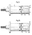
- Figure 5 is a side elevation of the bolt; and
- Figures 6 to 10 are views, corresponding to those of Figures 1 to 5, of another embodiment of the bolt.
- Reference is made to Figures 1 to 4. It is noted that reference numerals present in Figures 1 and 2 are not generally duplicated in Figures 3 and 4. This is for reasons of clarity. The purpose of the bolt is to ensure that two
mating components 2A and 2B are fixedly relatively secured in a vibration proof manner. For this purpose, the bolt is permanently in place relative to themating component 2B shown in Figure 1 and 2, and when component 2A is brought into contact with thecomponent 2B the bolt is done up until the components just mate, whereafter a predetermined torque is applied to maintain a secure connection. - The bolt comprises a shaft 1 screw threaded at one end 1a to engage a correspondingly screw threaded hole 30 in one 2A of the two
mating components 2A, 2B. The shaft 1 is formed with aportion 31 of larger diameter than that of the end 1a, thisportion 31 of larger diameter having aslot 5 formed therein. The shaft 1 also has aradial flange 35 and on one side of this flange 35 (to the right in Figure 1) asmaller diameter portion 36 extending within asleeve 17. Thesmaller diameter portion 36 is fixedly secured to thesleeve 17 to rotate therewith. It is possible however to replace one shaft by another to accommodate different sized shafts. The shaft 1 has apassageway 32 formed therein for receiving arod 8 of an indicating mechanism to be described in more detail hereinafter. - A
cylindrical casing 3 has aflange 37 to be secured to thecomponent 2B by means ofholes 38 in combination with screws or other suitable securing elements. As an alternative, thecasing 3 can be formed as part of thecomponent 2B. In any event, thecasing 3 enables the bolt to be left permanently in place relative tocomponent 2B, the shaft 1 passing through ahole 30B in thecomponent 2B aligned with the threadedhole 30A. Thecasing 3 has afront wall 39 provided with anaperture 40 for receiving thesleeve 17. Athrust washer 13 for extraction is provided between theflange 35 of the shaft and thefront wall 39 of thecasing 3. - The
casing 3 also carries an axially extendingcylindrical portion 41, having serrated teeth 6 the purpose of which is described in more detail hereinafter. - A rotatable grip 42 is fitted about the
sleeve 17, the grip 42 comprising anexternal collar 15 and a knob 44. The knob 44 carries a colour codedelastomeric cylinder 16. The colour coding is indicative of the maximum torque which can be applied by the bolt. Thecollar 15 can slide but not rotate relative to the knob 44. Theelastomeric cylinder 16 has four circumferentially spaced protrusions 50 which provide a biasing force against a recessed surface 51 of thecollar 15. Thecollar 15 is castellated so as to co-operate with respective ridges in thecollar 15 to provide resistance to turning theknob 16. This assists in preventing vibrational effects from undoing the bolt once secured. - The knob 44 has, at its right hand end as seen in Figure 1, a recess in which are disposed a pack of disc springs, (for example Belleville washers) 45. The springs are held in position by an
adjustable nut 18. Theadjustable nut 18 has in itssurface 18b a recessed or dished portion 18a the purpose of which will be described hereinafter. - The
axially extending portion 41 of thecasing 3 forms an annular recess which co-operates with thecollar 15 of rotatable grip 42 and thesleeve 17 to define an annular cavity housing a torque limiting arrangement 47. The torque limiting arrangement is as described in European Patent Application No. 83305061.0 (Publication No. 0105609) and comprises adrive plate 48 and a plurality ofball bearings 49. Operation of the arrangement is described in detail in EPA 0105609 and will hence not be described in more detail hereinafter. - The
collar 15 is removably secured to theaxially extending portion 41 of thecasing 3 via a positive self locking rachet mechanism. The rachet mechanism comprises the set of "saw teeth" 6 on theaxially extending portion 41 co-operating with a set ofsimilar teeth 14 on thecollar 15. The saw teeth are so shaped (see Figure 6) that the leading edge has a smaller gradient than the trailing edge whereby rotation of thecollar 15 of the grip 42 in one direction is permitted (the direction which cause the bolt to be tightened), against resistance caused by the action of the trailing surface of a tooth on thecollar 15 sliding "up and over" the leading surface of a tooth on theaxially extending portion 41. Rotation in the opposite direction is prevented unless thecollar 15 is pulled axially away, against the action of the protrusion 50 of theelastomeric cylinder 16, from theaxially extending portion 41 to release the teeth. Once done up, there is hence no danger of the bolt coming undone. - The indicating mechanism will now be described in detail. Reference numerals for components of the mechanism are shown only in Figure 2 for the sake of clarity. The mechanism includes a sleeve or collar 11 encircling the shaft 1 between the latter and the
hole 30B and a T-piece 12 located in apertures in the collar 11 and assembled onto one end of therod 8 so as to be slidable (with axial movement of the rod 8) along theslot 5. The T-piece 12 is secured to therod 8 by screwing. In this way, the operable length of therod 8 can be adjusted as described later. The collar 11 has aflange 53 between which and theflange 35 of the shaft 1 is arranged acoil spring 4. At the end of therod 8 remote from said one end is a rod guide 9 which is screw threadedly secured to therod 8. While it might be simplest to manufacture thepush rod 8 with a screw thread along its entire length, a screw thread is only required at the one end where it is connected to the T-piece 12 and at the other end where it is connected to the guide 9. An adjustingscrew 19 serves to attach anindicator spring 10 to the guide 9. Theindicator spring 10 can take the form of a planar resilient member such as a flat flexible member of cruciform shape (as illustrated) or an elastomeric disc. It will be apparent from the following description that other resilient members could be used, but the afore-mentioned forms have been found to be preferred. An important point however is that the resilient strength of theindicator spring 10 is less than the resilient strength of thecoil spring 4. The adjustingscrew 19 can adjust the position of therod 8 longitudinally relative to thepassageway 32. In this way, the bolt can be set up by positioning the collar 11 flush with the face ofconnector 2B and then adjusting the adjustingscrew 19 until theindicator spring 10 lies flat against the facingsurface 18b of thenut 18, as shown in Figure 3. To accommodate this adjustment, arecess 60 is provided in the shaft 1. - Operation of the bolt is as follows. In the unmated condition of the
components 2A, 2B, thespring 4 maintains the collar 11 in a position such that it protrudes through one of themating connectors 2B. - The
coil spring 4 overcomes the force exerted by theindicator spring 10 to pull the latter into the dished portion 18a of the adjustingnut 18, forcing thetags 10a of the cruciform spring 10 (or the periphery of an elastomeric disc) to protrude from thenut 18 to indicate the unmated condition of the connector. When the thread of the shaft 1 is engaged in the connector 2A, the knob 44 is rotated to draw the twoconnectors 2A, 2B together. As the knob 44 rotates it turns thecollar 15, the serrated teeth 6 of which are allowed to ride over theserrated teeth 14 of thecasing 3 against the pressure exerted by the circumferentially spaced protrusions of theelastomeric cylinder 16. As theconnectors 2A, 2B mate, the collar 11 is pushed back against the force of thespring 4 which causes the T-piece 12 and hence thepush rod 8 and guide 9 to be moved axially so as to permit theindicator spring 10 to resume its flat condition flush with thesurface 18b of thenut 18 as shown in Figure 3. The knob 44 is further rotated until the torque limit is reached [as described in the above-referenced European patent application] after which the torque limiting mechanism 47 will slip and the shaft 1 will no longer be driven. - Any anti-clockwise rotation of the knob 44 under vibration is prevented by the
collar 15 and the co-operation of itsserrated teeth 14 with the serrated teeth 6 under the reaction of the elastomeric protrusions 50. In order to undo the bolt and to separate theconnectors 2A, 2B, thecollar 15 must be pulled back against the force of theelastomeric cylinder 16 on the knob 44 to disengage the rachet of the serrated teeth and the whole knob rotated anti-clockwise. This must be repeated until the connectors are disengaged. However, as soon as the connectors part, the action ofspring 4 causes theindicator spring 10 to be pulled back making the tags protrude again. - Reference is now made to the embodiment shown in Figures 6 to 10, in which the
indicator spring 10 is replaced by anindicator lever 110. As this embodiment operates on the same principal as the embodiment described with reference to Figures 1 to 5, only the differences between the two embodiments will be described in the following. - An
adjustable nut 180 replaces theadjustable nut 18 of the first described embodiment. Theadjustable nut 180 has a slot formed in its surface.Indicator lever 110 is located within theslot 112 by apivot pin 114. In place of the rod guide 9, apush rod 116 may be connected to the end of therod 8. The end of thepush rod 116 is attached to the indicator lever by means of afurther pivot pin 118. The proximity of pivot points 114 and 118 serves to amplify the movement oflever 110 in response to movement ofpush rod 116. The width of the indicator lever is less than the diameter of thepush rod 116 in order that the indicator lever can be held axially with the push rod and both items screwed onto therod 8. In this way, the bolt can be set up by positioning the collar 11 flush with the face of the connector 2b and screwing the push rod complete with the indicator lever assembled on thepivot pin 118 until the indicator lever can be positioned at 90° relative to thepush rod 116, so that it lies flush within theslot adjusting nut 180 as shown in Figure 8. - Indicating mechanism operates substantially as described above. That is, the
coil spring 4 pulls the end of the indicator lever secured to thepush rod 116 thereby causing the opposite end region to protrude from the slot in the adjustingnut 180 to indicate the unmated condition of the connector. When mated, thepush rod 116 is moved axially to cause theindicator lever 110 to lie flush within the slot in the adjustingnut 180. - A particular feature of the described bolt is that the
thrust washer 48 keyed onto thesleeve 17 causes the components of the bolt to the left of thewall 39 to be maintained in tension relative to endwall 39. Vibrational effects on the bolt to the left ofend wall 39 are hence reduced. - Another important feature of the bolt is that the indicating mechanism provides an easily visible effect to show whether or not the components are mated. This can be seen most readily from Figure 1, in which the
cruciform tags 10a protrude to indicate the unmated condition. When the connectors are mated, thespring 10 lies flush with thesurface 18b. - The same is true of the embodiment of Figures 6 to 10 in which the indicator lever end protrudes to indicate the unmated condition, and, when the connectors are mated, lies flush within the slot.
Claims (7)
Priority Applications (1)
| Application Number | Priority Date | Filing Date | Title |
|---|---|---|---|
| AT88307475T ATE70402T1 (en) | 1987-08-18 | 1988-08-12 | CONNECTING ELEMENT. |
Applications Claiming Priority (2)
| Application Number | Priority Date | Filing Date | Title |
|---|---|---|---|
| GB8719484 | 1987-08-18 | ||
| GB878719484A GB8719484D0 (en) | 1987-08-18 | 1987-08-18 | Connector element |
Publications (2)
| Publication Number | Publication Date |
|---|---|
| EP0304237A1 EP0304237A1 (en) | 1989-02-22 |
| EP0304237B1 true EP0304237B1 (en) | 1991-12-11 |
Family
ID=10622428
Family Applications (1)
| Application Number | Title | Priority Date | Filing Date |
|---|---|---|---|
| EP88307475A Expired - Lifetime EP0304237B1 (en) | 1987-08-18 | 1988-08-12 | Connector element |
Country Status (6)
| Country | Link |
|---|---|
| US (1) | US4934884A (en) |
| EP (1) | EP0304237B1 (en) |
| AT (1) | ATE70402T1 (en) |
| DE (1) | DE3866825D1 (en) |
| ES (1) | ES2039036T3 (en) |
| GB (1) | GB8719484D0 (en) |
Cited By (1)
| Publication number | Priority date | Publication date | Assignee | Title |
|---|---|---|---|---|
| EP1758441A2 (en) | 2005-08-24 | 2007-02-28 | Engineering Dynamics (Southern) Limited | Screw-threaded fastening devices |
Families Citing this family (14)
| Publication number | Priority date | Publication date | Assignee | Title |
|---|---|---|---|---|
| GB8900663D0 (en) * | 1989-01-12 | 1989-03-08 | Barry Controls | Connector element |
| US5240361A (en) * | 1991-05-03 | 1993-08-31 | The Boeing Company | Limited force cartridge for temporary fasteners |
| US5668323A (en) * | 1996-07-12 | 1997-09-16 | Waxman; Cory S. | Method and apparatus for indicating a load |
| US6089525A (en) * | 1997-10-07 | 2000-07-18 | Ultratech Stepper, Inc. | Six axis active vibration isolation and payload reaction force compensation system |
| US6030305A (en) * | 1998-09-28 | 2000-02-29 | Ingersoll-Rand Company | Semi-automatic tensioner for a belt drive system |
| US6285564B1 (en) * | 2000-03-24 | 2001-09-04 | Keystone Electronics Packaging, Inc. | Circuit card retainer assembly |
| WO2005111438A1 (en) * | 2004-05-19 | 2005-11-24 | Vibrosystm Inc. | Shear component breakage detection |
| US8024979B2 (en) * | 2006-08-24 | 2011-09-27 | Clarke Ronald C | Indicating fastener loading |
| US7520174B2 (en) * | 2006-08-24 | 2009-04-21 | Ronald C. Clarke | Method and apparatus for indicating a load |
| US8128074B2 (en) * | 2006-11-14 | 2012-03-06 | General Electric Company | Automatic tensioning mount for belts |
| WO2015098141A1 (en) * | 2013-12-27 | 2015-07-02 | 株式会社ロックン・ボルト | Bolt |
| US10040152B2 (en) * | 2015-08-17 | 2018-08-07 | GM Global Technology Operations LLC | Mechanical lock for a work support |
| US10041518B1 (en) * | 2017-01-09 | 2018-08-07 | Heartland Precision Fasteners, Inc. | Captive screw |
| US12497987B1 (en) * | 2025-04-08 | 2025-12-16 | The Boeing Company | Cartridge mechanism and method for monitoring a clamping force exerted on a structure by a fastener during installation |
Family Cites Families (12)
| Publication number | Priority date | Publication date | Assignee | Title |
|---|---|---|---|---|
| GB828194A (en) * | 1955-09-20 | 1960-02-17 | Nat Res Dev | Captive screw fasteners |
| US3273443A (en) * | 1964-02-28 | 1966-09-20 | Norman N Rubin | Torque limiting nut |
| BE665715A (en) * | 1964-07-01 | |||
| US3294140A (en) * | 1964-09-02 | 1966-12-27 | Calfax Inc | Panel fastener |
| US3368602A (en) * | 1966-04-01 | 1968-02-13 | Tridair Industries | Self-locking captive screw assembly |
| US3555491A (en) * | 1969-03-20 | 1971-01-12 | Bendix Corp | Electrical connector |
| US3683988A (en) * | 1970-03-03 | 1972-08-15 | Textron Inc | Positive lock structural fastener |
| DE2112587B1 (en) * | 1971-12-15 | 1972-09-14 | Stop Choc Schwingungstechnik G | Locking device on a frame for holding electronic devices |
| IL66290A (en) * | 1981-07-28 | 1985-12-31 | Rexnord Inc | Swing fastening device particularly for securing electronic units |
| EP0105609B1 (en) * | 1982-09-03 | 1989-03-01 | Barry Wright Corporation | Apparatus for securing an electronic unit to an avionics tray |
| US4720223A (en) * | 1985-05-07 | 1988-01-19 | Rexnord Inc. | Controlled preload, self-retracting captive fastener assembly |
| US4692075A (en) * | 1986-05-02 | 1987-09-08 | Norco,Inc. | Panel fastener |
-
1987
- 1987-08-18 GB GB878719484A patent/GB8719484D0/en active Pending
-
1988
- 1988-08-12 EP EP88307475A patent/EP0304237B1/en not_active Expired - Lifetime
- 1988-08-12 DE DE8888307475T patent/DE3866825D1/en not_active Expired - Fee Related
- 1988-08-12 ES ES198888307475T patent/ES2039036T3/en not_active Expired - Lifetime
- 1988-08-12 AT AT88307475T patent/ATE70402T1/en not_active IP Right Cessation
- 1988-08-15 US US07/232,360 patent/US4934884A/en not_active Expired - Lifetime
Cited By (1)
| Publication number | Priority date | Publication date | Assignee | Title |
|---|---|---|---|---|
| EP1758441A2 (en) | 2005-08-24 | 2007-02-28 | Engineering Dynamics (Southern) Limited | Screw-threaded fastening devices |
Also Published As
| Publication number | Publication date |
|---|---|
| EP0304237A1 (en) | 1989-02-22 |
| GB8719484D0 (en) | 1987-09-23 |
| ATE70402T1 (en) | 1991-12-15 |
| US4934884A (en) | 1990-06-19 |
| DE3866825D1 (en) | 1992-01-23 |
| ES2039036T3 (en) | 1993-08-16 |
Similar Documents
| Publication | Publication Date | Title |
|---|---|---|
| US4934884A (en) | Connector element | |
| EP0297711B1 (en) | Coupling arrangements | |
| EP0333410A2 (en) | Screw-coupled connectors | |
| US4637502A (en) | Overload release mechanism for torque couplings | |
| US6796385B1 (en) | Fastener driving machine and associated method | |
| EP0071559B1 (en) | Fastener of the hold-down type | |
| US4830530A (en) | Hold-down device | |
| US6340074B1 (en) | Pad wear compensator for a disc brake caliper | |
| US4512697A (en) | Torque limiting fastener | |
| EP0414835B1 (en) | Connector element | |
| JPH0263320B2 (en) | ||
| US7780386B2 (en) | Torque-limited electrical connector | |
| US2786378A (en) | Torque tool and release mechanism | |
| EP0323166A2 (en) | Wrench | |
| US4968201A (en) | Adaptor for screwing or unscrewing threaded connection elements | |
| US11173586B2 (en) | Disengaging socket extension | |
| GB2150231A (en) | Device for fixing a thrust bearing | |
| WO1987007089A1 (en) | Screw-coupled connectors | |
| US20070048105A1 (en) | Screw-threaded fastening devices | |
| EP0517645A1 (en) | Catch for a shaft for mounting a knife in a mower and a knife device comprising such catch | |
| EP0174072A2 (en) | Releasable connector device | |
| US4065217A (en) | Nose tip locking device | |
| US2795857A (en) | Ring gauge protective device | |
| US4919036A (en) | Arresting apparatus for fixation of an adjusted position | |
| KR102339017B1 (en) | the unlock apparatus of brake for servomotor and the brake for servomotor therewith |
Legal Events
| Date | Code | Title | Description |
|---|---|---|---|
| PUAI | Public reference made under article 153(3) epc to a published international application that has entered the european phase |
Free format text: ORIGINAL CODE: 0009012 |
|
| 17P | Request for examination filed |
Effective date: 19880826 |
|
| AK | Designated contracting states |
Kind code of ref document: A1 Designated state(s): AT DE ES FR GB GR IT SE |
|
| 17Q | First examination report despatched |
Effective date: 19910228 |
|
| GRAA | (expected) grant |
Free format text: ORIGINAL CODE: 0009210 |
|
| AK | Designated contracting states |
Kind code of ref document: B1 Designated state(s): AT DE ES FR GB GR IT SE |
|
| PG25 | Lapsed in a contracting state [announced via postgrant information from national office to epo] |
Ref country code: SE Effective date: 19911211 Ref country code: GR Free format text: LAPSE BECAUSE OF FAILURE TO SUBMIT A TRANSLATION OF THE DESCRIPTION OR TO PAY THE FEE WITHIN THE PRESCRIBED TIME-LIMIT Effective date: 19911211 Ref country code: AT Effective date: 19911211 |
|
| REF | Corresponds to: |
Ref document number: 70402 Country of ref document: AT Date of ref document: 19911215 Kind code of ref document: T |
|
| REF | Corresponds to: |
Ref document number: 3866825 Country of ref document: DE Date of ref document: 19920123 |
|
| ITF | It: translation for a ep patent filed | ||
| ET | Fr: translation filed | ||
| PLBE | No opposition filed within time limit |
Free format text: ORIGINAL CODE: 0009261 |
|
| STAA | Information on the status of an ep patent application or granted ep patent |
Free format text: STATUS: NO OPPOSITION FILED WITHIN TIME LIMIT |
|
| 26N | No opposition filed | ||
| REG | Reference to a national code |
Ref country code: ES Ref legal event code: FG2A Ref document number: 2039036 Country of ref document: ES Kind code of ref document: T3 |
|
| REG | Reference to a national code |
Ref country code: GB Ref legal event code: IF02 |
|
| PGFP | Annual fee paid to national office [announced via postgrant information from national office to epo] |
Ref country code: FR Payment date: 20030627 Year of fee payment: 16 |
|
| PGFP | Annual fee paid to national office [announced via postgrant information from national office to epo] |
Ref country code: GB Payment date: 20030728 Year of fee payment: 16 |
|
| PGFP | Annual fee paid to national office [announced via postgrant information from national office to epo] |
Ref country code: DE Payment date: 20030805 Year of fee payment: 16 |
|
| PGFP | Annual fee paid to national office [announced via postgrant information from national office to epo] |
Ref country code: ES Payment date: 20030807 Year of fee payment: 16 |
|
| PG25 | Lapsed in a contracting state [announced via postgrant information from national office to epo] |
Ref country code: GB Free format text: LAPSE BECAUSE OF NON-PAYMENT OF DUE FEES Effective date: 20040812 |
|
| PG25 | Lapsed in a contracting state [announced via postgrant information from national office to epo] |
Ref country code: ES Free format text: LAPSE BECAUSE OF NON-PAYMENT OF DUE FEES Effective date: 20040813 |
|
| PG25 | Lapsed in a contracting state [announced via postgrant information from national office to epo] |
Ref country code: DE Free format text: LAPSE BECAUSE OF NON-PAYMENT OF DUE FEES Effective date: 20050301 |
|
| GBPC | Gb: european patent ceased through non-payment of renewal fee |
Effective date: 20040812 |
|
| PG25 | Lapsed in a contracting state [announced via postgrant information from national office to epo] |
Ref country code: FR Free format text: LAPSE BECAUSE OF NON-PAYMENT OF DUE FEES Effective date: 20050429 |
|
| REG | Reference to a national code |
Ref country code: FR Ref legal event code: ST |
|
| PG25 | Lapsed in a contracting state [announced via postgrant information from national office to epo] |
Ref country code: IT Free format text: LAPSE BECAUSE OF NON-PAYMENT OF DUE FEES;WARNING: LAPSES OF ITALIAN PATENTS WITH EFFECTIVE DATE BEFORE 2007 MAY HAVE OCCURRED AT ANY TIME BEFORE 2007. THE CORRECT EFFECTIVE DATE MAY BE DIFFERENT FROM THE ONE RECORDED. Effective date: 20050812 |
|
| REG | Reference to a national code |
Ref country code: ES Ref legal event code: FD2A Effective date: 20040813 |