EP0303693B1 - Electrical components produced from a nonisotropic solution polarizable material - Google Patents
Electrical components produced from a nonisotropic solution polarizable material Download PDFInfo
- Publication number
- EP0303693B1 EP0303693B1 EP88903503A EP88903503A EP0303693B1 EP 0303693 B1 EP0303693 B1 EP 0303693B1 EP 88903503 A EP88903503 A EP 88903503A EP 88903503 A EP88903503 A EP 88903503A EP 0303693 B1 EP0303693 B1 EP 0303693B1
- Authority
- EP
- European Patent Office
- Prior art keywords
- soap
- capacitor
- nonisotropic
- compound
- liquid
- Prior art date
- Legal status (The legal status is an assumption and is not a legal conclusion. Google has not performed a legal analysis and makes no representation as to the accuracy of the status listed.)
- Expired - Lifetime
Links
- 239000000463 material Substances 0.000 title claims abstract description 34
- 239000000344 soap Substances 0.000 claims abstract description 133
- 239000003990 capacitor Substances 0.000 claims abstract description 41
- 239000003792 electrolyte Substances 0.000 claims abstract description 20
- XLYOFNOQVPJJNP-UHFFFAOYSA-N water Substances O XLYOFNOQVPJJNP-UHFFFAOYSA-N 0.000 claims description 39
- 150000001875 compounds Chemical class 0.000 claims description 31
- 239000007788 liquid Substances 0.000 claims description 26
- 238000003860 storage Methods 0.000 claims description 26
- 235000014113 dietary fatty acids Nutrition 0.000 claims description 22
- 239000000194 fatty acid Substances 0.000 claims description 22
- 229930195729 fatty acid Natural products 0.000 claims description 22
- 239000004973 liquid crystal related substance Substances 0.000 claims description 22
- -1 alkali metal salts Chemical class 0.000 claims description 18
- 239000000203 mixture Substances 0.000 claims description 17
- 150000004665 fatty acids Chemical class 0.000 claims description 14
- 150000003839 salts Chemical class 0.000 claims description 12
- 229910052782 aluminium Inorganic materials 0.000 claims description 9
- XAGFODPZIPBFFR-UHFFFAOYSA-N aluminium Chemical compound [Al] XAGFODPZIPBFFR-UHFFFAOYSA-N 0.000 claims description 8
- RYYKJJJTJZKILX-UHFFFAOYSA-M sodium octadecanoate Chemical compound [Na+].CCCCCCCCCCCCCCCCCC([O-])=O RYYKJJJTJZKILX-UHFFFAOYSA-M 0.000 claims description 6
- KAKVFSYQVNHFBS-UHFFFAOYSA-N (5-hydroxycyclopenten-1-yl)-phenylmethanone Chemical compound OC1CCC=C1C(=O)C1=CC=CC=C1 KAKVFSYQVNHFBS-UHFFFAOYSA-N 0.000 claims description 5
- 239000003989 dielectric material Substances 0.000 claims description 5
- 229910052751 metal Inorganic materials 0.000 claims description 5
- 239000002184 metal Substances 0.000 claims description 5
- 229940114930 potassium stearate Drugs 0.000 claims description 5
- ANBFRLKBEIFNQU-UHFFFAOYSA-M potassium;octadecanoate Chemical compound [K+].CCCCCCCCCCCCCCCCCC([O-])=O ANBFRLKBEIFNQU-UHFFFAOYSA-M 0.000 claims description 5
- BTURAGWYSMTVOW-UHFFFAOYSA-M sodium dodecanoate Chemical compound [Na+].CCCCCCCCCCCC([O-])=O BTURAGWYSMTVOW-UHFFFAOYSA-M 0.000 claims description 5
- 229940082004 sodium laurate Drugs 0.000 claims description 5
- 229940045845 sodium myristate Drugs 0.000 claims description 5
- 229940045870 sodium palmitate Drugs 0.000 claims description 5
- GGXKEBACDBNFAF-UHFFFAOYSA-M sodium;hexadecanoate Chemical compound [Na+].CCCCCCCCCCCCCCCC([O-])=O GGXKEBACDBNFAF-UHFFFAOYSA-M 0.000 claims description 5
- JUQGWKYSEXPRGL-UHFFFAOYSA-M sodium;tetradecanoate Chemical compound [Na+].CCCCCCCCCCCCCC([O-])=O JUQGWKYSEXPRGL-UHFFFAOYSA-M 0.000 claims description 5
- XLYOFNOQVPJJNP-ZSJDYOACSA-N Heavy water Chemical compound [2H]O[2H] XLYOFNOQVPJJNP-ZSJDYOACSA-N 0.000 claims description 4
- 229910052784 alkaline earth metal Inorganic materials 0.000 claims description 4
- 230000005684 electric field Effects 0.000 claims description 4
- 229910052783 alkali metal Inorganic materials 0.000 claims description 3
- 150000003863 ammonium salts Chemical class 0.000 claims description 3
- DGAQECJNVWCQMB-PUAWFVPOSA-M Ilexoside XXIX Chemical compound C[C@@H]1CC[C@@]2(CC[C@@]3(C(=CC[C@H]4[C@]3(CC[C@@H]5[C@@]4(CC[C@@H](C5(C)C)OS(=O)(=O)[O-])C)C)[C@@H]2[C@]1(C)O)C)C(=O)O[C@H]6[C@@H]([C@H]([C@@H]([C@H](O6)CO)O)O)O.[Na+] DGAQECJNVWCQMB-PUAWFVPOSA-M 0.000 claims description 2
- WHXSMMKQMYFTQS-UHFFFAOYSA-N Lithium Chemical compound [Li] WHXSMMKQMYFTQS-UHFFFAOYSA-N 0.000 claims description 2
- 159000000006 cesium salts Chemical class 0.000 claims description 2
- JEGUKCSWCFPDGT-UHFFFAOYSA-N h2o hydrate Chemical compound O.O JEGUKCSWCFPDGT-UHFFFAOYSA-N 0.000 claims description 2
- 229910052744 lithium Inorganic materials 0.000 claims description 2
- 229910052700 potassium Inorganic materials 0.000 claims description 2
- 229910052708 sodium Inorganic materials 0.000 claims description 2
- 239000011734 sodium Substances 0.000 claims description 2
- ZLMJMSJWJFRBEC-UHFFFAOYSA-N Potassium Chemical compound [K] ZLMJMSJWJFRBEC-UHFFFAOYSA-N 0.000 claims 1
- 229910000831 Steel Inorganic materials 0.000 claims 1
- 239000002001 electrolyte material Substances 0.000 claims 1
- 150000002739 metals Chemical class 0.000 claims 1
- 239000011591 potassium Substances 0.000 claims 1
- 229910052701 rubidium Inorganic materials 0.000 claims 1
- IGLNJRXAVVLDKE-UHFFFAOYSA-N rubidium atom Chemical compound [Rb] IGLNJRXAVVLDKE-UHFFFAOYSA-N 0.000 claims 1
- 229940023574 sodium palmate Drugs 0.000 claims 1
- 229940080350 sodium stearate Drugs 0.000 claims 1
- 239000010959 steel Substances 0.000 claims 1
- 239000007787 solid Substances 0.000 abstract description 50
- 239000000243 solution Substances 0.000 abstract description 25
- 239000006104 solid solution Substances 0.000 abstract description 3
- 239000000523 sample Substances 0.000 description 30
- FAPWRFPIFSIZLT-UHFFFAOYSA-M Sodium chloride Chemical compound [Na+].[Cl-] FAPWRFPIFSIZLT-UHFFFAOYSA-M 0.000 description 18
- 238000000034 method Methods 0.000 description 14
- 239000011888 foil Substances 0.000 description 10
- 238000005259 measurement Methods 0.000 description 9
- 239000011780 sodium chloride Substances 0.000 description 9
- 239000003760 tallow Substances 0.000 description 8
- 239000003240 coconut oil Substances 0.000 description 5
- 235000019864 coconut oil Nutrition 0.000 description 5
- 230000000694 effects Effects 0.000 description 5
- 238000005516 engineering process Methods 0.000 description 5
- 238000002474 experimental method Methods 0.000 description 5
- 238000010587 phase diagram Methods 0.000 description 5
- 239000000126 substance Substances 0.000 description 5
- 239000003925 fat Substances 0.000 description 4
- 230000008569 process Effects 0.000 description 4
- 238000012360 testing method Methods 0.000 description 4
- 230000007704 transition Effects 0.000 description 4
- 244000060011 Cocos nucifera Species 0.000 description 3
- 235000013162 Cocos nucifera Nutrition 0.000 description 3
- HEMHJVSKTPXQMS-UHFFFAOYSA-M Sodium hydroxide Chemical compound [OH-].[Na+] HEMHJVSKTPXQMS-UHFFFAOYSA-M 0.000 description 3
- 210000000085 cashmere Anatomy 0.000 description 3
- 239000001913 cellulose Substances 0.000 description 3
- 229920002678 cellulose Polymers 0.000 description 3
- 239000000470 constituent Substances 0.000 description 3
- 238000009826 distribution Methods 0.000 description 3
- 235000019197 fats Nutrition 0.000 description 3
- PCHJSUWPFVWCPO-UHFFFAOYSA-N gold Chemical compound [Au] PCHJSUWPFVWCPO-UHFFFAOYSA-N 0.000 description 3
- 239000010931 gold Substances 0.000 description 3
- 229910052737 gold Inorganic materials 0.000 description 3
- 230000004044 response Effects 0.000 description 3
- 229910001220 stainless steel Inorganic materials 0.000 description 3
- 239000010935 stainless steel Substances 0.000 description 3
- 229910000619 316 stainless steel Inorganic materials 0.000 description 2
- OKTJSMMVPCPJKN-UHFFFAOYSA-N Carbon Chemical compound [C] OKTJSMMVPCPJKN-UHFFFAOYSA-N 0.000 description 2
- 239000000654 additive Substances 0.000 description 2
- 229910052799 carbon Inorganic materials 0.000 description 2
- 238000001816 cooling Methods 0.000 description 2
- 239000006185 dispersion Substances 0.000 description 2
- 238000001125 extrusion Methods 0.000 description 2
- 239000011152 fibreglass Substances 0.000 description 2
- 125000005456 glyceride group Chemical group 0.000 description 2
- 238000010438 heat treatment Methods 0.000 description 2
- 230000002535 lyotropic effect Effects 0.000 description 2
- 239000000693 micelle Substances 0.000 description 2
- 239000002480 mineral oil Substances 0.000 description 2
- 235000010446 mineral oil Nutrition 0.000 description 2
- QIQXTHQIDYTFRH-UHFFFAOYSA-N octadecanoic acid Chemical compound CCCCCCCCCCCCCCCCCC(O)=O QIQXTHQIDYTFRH-UHFFFAOYSA-N 0.000 description 2
- 239000003921 oil Substances 0.000 description 2
- 235000019198 oils Nutrition 0.000 description 2
- 229920006254 polymer film Polymers 0.000 description 2
- 238000002360 preparation method Methods 0.000 description 2
- 230000035945 sensitivity Effects 0.000 description 2
- 125000006850 spacer group Chemical group 0.000 description 2
- 150000004670 unsaturated fatty acids Chemical class 0.000 description 2
- 235000021122 unsaturated fatty acids Nutrition 0.000 description 2
- 239000001993 wax Substances 0.000 description 2
- WRIDQFICGBMAFQ-UHFFFAOYSA-N (E)-8-Octadecenoic acid Natural products CCCCCCCCCC=CCCCCCCC(O)=O WRIDQFICGBMAFQ-UHFFFAOYSA-N 0.000 description 1
- LQJBNNIYVWPHFW-UHFFFAOYSA-N 20:1omega9c fatty acid Natural products CCCCCCCCCCC=CCCCCCCCC(O)=O LQJBNNIYVWPHFW-UHFFFAOYSA-N 0.000 description 1
- QSBYPNXLFMSGKH-UHFFFAOYSA-N 9-Heptadecensaeure Natural products CCCCCCCC=CCCCCCCCC(O)=O QSBYPNXLFMSGKH-UHFFFAOYSA-N 0.000 description 1
- RSWGJHLUYNHPMX-UHFFFAOYSA-N Abietic-Saeure Natural products C12CCC(C(C)C)=CC2=CCC2C1(C)CCCC2(C)C(O)=O RSWGJHLUYNHPMX-UHFFFAOYSA-N 0.000 description 1
- QGZKDVFQNNGYKY-UHFFFAOYSA-O Ammonium Chemical compound [NH4+] QGZKDVFQNNGYKY-UHFFFAOYSA-O 0.000 description 1
- 229930185605 Bisphenol Natural products 0.000 description 1
- 239000004215 Carbon black (E152) Substances 0.000 description 1
- RYGMFSIKBFXOCR-UHFFFAOYSA-N Copper Chemical compound [Cu] RYGMFSIKBFXOCR-UHFFFAOYSA-N 0.000 description 1
- 241001465754 Metazoa Species 0.000 description 1
- ZQPPMHVWECSIRJ-UHFFFAOYSA-N Oleic acid Natural products CCCCCCCCC=CCCCCCCCC(O)=O ZQPPMHVWECSIRJ-UHFFFAOYSA-N 0.000 description 1
- 239000005642 Oleic acid Substances 0.000 description 1
- 235000019482 Palm oil Nutrition 0.000 description 1
- 235000019483 Peanut oil Nutrition 0.000 description 1
- 239000004743 Polypropylene Substances 0.000 description 1
- KHPCPRHQVVSZAH-HUOMCSJISA-N Rosin Natural products O(C/C=C/c1ccccc1)[C@H]1[C@H](O)[C@@H](O)[C@@H](O)[C@@H](CO)O1 KHPCPRHQVVSZAH-HUOMCSJISA-N 0.000 description 1
- 230000018199 S phase Effects 0.000 description 1
- 239000004990 Smectic liquid crystal Substances 0.000 description 1
- BCKXLBQYZLBQEK-KVVVOXFISA-M Sodium oleate Chemical compound [Na+].CCCCCCCC\C=C/CCCCCCCC([O-])=O BCKXLBQYZLBQEK-KVVVOXFISA-M 0.000 description 1
- 239000003568 Sodium, potassium and calcium salts of fatty acids Substances 0.000 description 1
- 235000021355 Stearic acid Nutrition 0.000 description 1
- 238000010521 absorption reaction Methods 0.000 description 1
- 230000009471 action Effects 0.000 description 1
- 230000000996 additive effect Effects 0.000 description 1
- 125000001931 aliphatic group Chemical group 0.000 description 1
- 150000001342 alkaline earth metals Chemical class 0.000 description 1
- 230000000844 anti-bacterial effect Effects 0.000 description 1
- 229940088710 antibiotic agent Drugs 0.000 description 1
- 239000007864 aqueous solution Substances 0.000 description 1
- KQLYFVFFPVJGRM-NBTZWHCOSA-N azanium;(9z,12z)-octadeca-9,12-dienoate Chemical compound [NH4+].CCCCC\C=C/C\C=C/CCCCCCCC([O-])=O KQLYFVFFPVJGRM-NBTZWHCOSA-N 0.000 description 1
- 239000010480 babassu oil Substances 0.000 description 1
- 230000004888 barrier function Effects 0.000 description 1
- 239000002585 base Substances 0.000 description 1
- 239000011324 bead Substances 0.000 description 1
- 229910002056 binary alloy Inorganic materials 0.000 description 1
- 230000015572 biosynthetic process Effects 0.000 description 1
- IISBACLAFKSPIT-UHFFFAOYSA-N bisphenol A Chemical compound C=1C=C(O)C=CC=1C(C)(C)C1=CC=C(O)C=C1 IISBACLAFKSPIT-UHFFFAOYSA-N 0.000 description 1
- 238000009529 body temperature measurement Methods 0.000 description 1
- 125000004432 carbon atom Chemical group C* 0.000 description 1
- 239000004359 castor oil Substances 0.000 description 1
- 235000019438 castor oil Nutrition 0.000 description 1
- 239000003518 caustics Substances 0.000 description 1
- 229920002301 cellulose acetate Polymers 0.000 description 1
- 230000008859 change Effects 0.000 description 1
- 239000011248 coating agent Substances 0.000 description 1
- 238000000576 coating method Methods 0.000 description 1
- 239000003086 colorant Substances 0.000 description 1
- 238000010276 construction Methods 0.000 description 1
- 229910052802 copper Inorganic materials 0.000 description 1
- 239000010949 copper Substances 0.000 description 1
- 239000002385 cottonseed oil Substances 0.000 description 1
- 235000012343 cottonseed oil Nutrition 0.000 description 1
- 230000001419 dependent effect Effects 0.000 description 1
- 238000000151 deposition Methods 0.000 description 1
- 238000013461 design Methods 0.000 description 1
- QULFJTHSOKWNOI-UHFFFAOYSA-L disodium octadecanoate chloride hydrate Chemical compound O.[Cl-].[Na+].C(CCCCCCCCCCCCCCCCC)(=O)[O-].[Na+] QULFJTHSOKWNOI-UHFFFAOYSA-L 0.000 description 1
- 238000001035 drying Methods 0.000 description 1
- 238000004146 energy storage Methods 0.000 description 1
- 238000001704 evaporation Methods 0.000 description 1
- 230000008020 evaporation Effects 0.000 description 1
- 230000001747 exhibiting effect Effects 0.000 description 1
- 239000004744 fabric Substances 0.000 description 1
- 239000000835 fiber Substances 0.000 description 1
- 229940013317 fish oils Drugs 0.000 description 1
- 239000003205 fragrance Substances 0.000 description 1
- ZEMPKEQAKRGZGQ-XOQCFJPHSA-N glycerol triricinoleate Natural products CCCCCC[C@@H](O)CC=CCCCCCCCC(=O)OC[C@@H](COC(=O)CCCCCCCC=CC[C@@H](O)CCCCCC)OC(=O)CCCCCCCC=CC[C@H](O)CCCCCC ZEMPKEQAKRGZGQ-XOQCFJPHSA-N 0.000 description 1
- 239000004519 grease Substances 0.000 description 1
- IPCSVZSSVZVIGE-UHFFFAOYSA-M hexadecanoate Chemical compound CCCCCCCCCCCCCCCC([O-])=O IPCSVZSSVZVIGE-UHFFFAOYSA-M 0.000 description 1
- 229930195733 hydrocarbon Natural products 0.000 description 1
- 150000002430 hydrocarbons Chemical class 0.000 description 1
- 230000007062 hydrolysis Effects 0.000 description 1
- 238000006460 hydrolysis reaction Methods 0.000 description 1
- 230000002209 hydrophobic effect Effects 0.000 description 1
- 230000006872 improvement Effects 0.000 description 1
- 239000012535 impurity Substances 0.000 description 1
- QXJSBBXBKPUZAA-UHFFFAOYSA-N isooleic acid Natural products CCCCCCCC=CCCCCCCCCC(O)=O QXJSBBXBKPUZAA-UHFFFAOYSA-N 0.000 description 1
- 239000000944 linseed oil Substances 0.000 description 1
- 235000021388 linseed oil Nutrition 0.000 description 1
- 238000004519 manufacturing process Methods 0.000 description 1
- 239000004200 microcrystalline wax Substances 0.000 description 1
- 235000019808 microcrystalline wax Nutrition 0.000 description 1
- 238000003801 milling Methods 0.000 description 1
- 238000002156 mixing Methods 0.000 description 1
- 239000012454 non-polar solvent Substances 0.000 description 1
- OQCDKBAXFALNLD-UHFFFAOYSA-N octadecanoic acid Natural products CCCCCCCC(C)CCCCCCCCC(O)=O OQCDKBAXFALNLD-UHFFFAOYSA-N 0.000 description 1
- ZQPPMHVWECSIRJ-KTKRTIGZSA-N oleic acid Chemical compound CCCCCCCC\C=C/CCCCCCCC(O)=O ZQPPMHVWECSIRJ-KTKRTIGZSA-N 0.000 description 1
- 239000004006 olive oil Substances 0.000 description 1
- 235000008390 olive oil Nutrition 0.000 description 1
- 239000011368 organic material Substances 0.000 description 1
- TWNQGVIAIRXVLR-UHFFFAOYSA-N oxo(oxoalumanyloxy)alumane Chemical compound O=[Al]O[Al]=O TWNQGVIAIRXVLR-UHFFFAOYSA-N 0.000 description 1
- 239000003346 palm kernel oil Substances 0.000 description 1
- 235000019865 palm kernel oil Nutrition 0.000 description 1
- 239000002540 palm oil Substances 0.000 description 1
- 239000012188 paraffin wax Substances 0.000 description 1
- 239000002245 particle Substances 0.000 description 1
- 239000000312 peanut oil Substances 0.000 description 1
- 230000000704 physical effect Effects 0.000 description 1
- 239000004033 plastic Substances 0.000 description 1
- 239000002798 polar solvent Substances 0.000 description 1
- 230000010287 polarization Effects 0.000 description 1
- 239000004417 polycarbonate Substances 0.000 description 1
- 229920000515 polycarbonate Polymers 0.000 description 1
- 125000003367 polycyclic group Chemical group 0.000 description 1
- 229920001155 polypropylene Polymers 0.000 description 1
- ZDCPCNYMFTYBBX-UHFFFAOYSA-N potassium rubidium Chemical compound [K].[Rb] ZDCPCNYMFTYBBX-UHFFFAOYSA-N 0.000 description 1
- 239000003755 preservative agent Substances 0.000 description 1
- 230000003716 rejuvenation Effects 0.000 description 1
- 238000011160 research Methods 0.000 description 1
- 239000011347 resin Substances 0.000 description 1
- 229920005989 resin Polymers 0.000 description 1
- 239000012261 resinous substance Substances 0.000 description 1
- 238000007127 saponification reaction Methods 0.000 description 1
- 229920006395 saturated elastomer Polymers 0.000 description 1
- 238000007493 shaping process Methods 0.000 description 1
- 239000000377 silicon dioxide Substances 0.000 description 1
- VYPSYNLAJGMNEJ-UHFFFAOYSA-N silicon dioxide Inorganic materials O=[Si]=O VYPSYNLAJGMNEJ-UHFFFAOYSA-N 0.000 description 1
- PBWTYEPSIRGDNW-UHFFFAOYSA-M sodium hexadecanoate hydrate Chemical compound [OH-].[Na+].CCCCCCCCCCCCCCCC(O)=O PBWTYEPSIRGDNW-UHFFFAOYSA-M 0.000 description 1
- 235000013875 sodium salts of fatty acid Nutrition 0.000 description 1
- 229940114926 stearate Drugs 0.000 description 1
- 239000008117 stearic acid Substances 0.000 description 1
- 239000003784 tall oil Substances 0.000 description 1
- KHPCPRHQVVSZAH-UHFFFAOYSA-N trans-cinnamyl beta-D-glucopyranoside Natural products OC1C(O)C(O)C(CO)OC1OCC=CC1=CC=CC=C1 KHPCPRHQVVSZAH-UHFFFAOYSA-N 0.000 description 1
- 235000015112 vegetable and seed oil Nutrition 0.000 description 1
- 235000019871 vegetable fat Nutrition 0.000 description 1
- 239000008158 vegetable oil Substances 0.000 description 1
- 239000003981 vehicle Substances 0.000 description 1
- 238000005303 weighing Methods 0.000 description 1
- 230000004580 weight loss Effects 0.000 description 1
Images









Classifications
-
- H—ELECTRICITY
- H01—ELECTRIC ELEMENTS
- H01G—CAPACITORS; CAPACITORS, RECTIFIERS, DETECTORS, SWITCHING DEVICES, LIGHT-SENSITIVE OR TEMPERATURE-SENSITIVE DEVICES OF THE ELECTROLYTIC TYPE
- H01G9/00—Electrolytic capacitors, rectifiers, detectors, switching devices, light-sensitive or temperature-sensitive devices; Processes of their manufacture
- H01G9/004—Details
- H01G9/08—Housing; Encapsulation
-
- H—ELECTRICITY
- H01—ELECTRIC ELEMENTS
- H01M—PROCESSES OR MEANS, e.g. BATTERIES, FOR THE DIRECT CONVERSION OF CHEMICAL ENERGY INTO ELECTRICAL ENERGY
- H01M6/00—Primary cells; Manufacture thereof
- H01M6/04—Cells with aqueous electrolyte
- H01M6/045—Cells with aqueous electrolyte characterised by aqueous electrolyte
-
- H—ELECTRICITY
- H01—ELECTRIC ELEMENTS
- H01G—CAPACITORS; CAPACITORS, RECTIFIERS, DETECTORS, SWITCHING DEVICES, LIGHT-SENSITIVE OR TEMPERATURE-SENSITIVE DEVICES OF THE ELECTROLYTIC TYPE
- H01G11/00—Hybrid capacitors, i.e. capacitors having different positive and negative electrodes; Electric double-layer [EDL] capacitors; Processes for the manufacture thereof or of parts thereof
- H01G11/54—Electrolytes
- H01G11/58—Liquid electrolytes
- H01G11/62—Liquid electrolytes characterised by the solute, e.g. salts, anions or cations therein
-
- H—ELECTRICITY
- H01—ELECTRIC ELEMENTS
- H01G—CAPACITORS; CAPACITORS, RECTIFIERS, DETECTORS, SWITCHING DEVICES, LIGHT-SENSITIVE OR TEMPERATURE-SENSITIVE DEVICES OF THE ELECTROLYTIC TYPE
- H01G4/00—Fixed capacitors; Processes of their manufacture
- H01G4/002—Details
- H01G4/018—Dielectrics
- H01G4/04—Liquid dielectrics
-
- H—ELECTRICITY
- H01—ELECTRIC ELEMENTS
- H01G—CAPACITORS; CAPACITORS, RECTIFIERS, DETECTORS, SWITCHING DEVICES, LIGHT-SENSITIVE OR TEMPERATURE-SENSITIVE DEVICES OF THE ELECTROLYTIC TYPE
- H01G4/00—Fixed capacitors; Processes of their manufacture
- H01G4/002—Details
- H01G4/018—Dielectrics
- H01G4/20—Dielectrics using combinations of dielectrics from more than one of groups H01G4/02 - H01G4/06
- H01G4/22—Dielectrics using combinations of dielectrics from more than one of groups H01G4/02 - H01G4/06 impregnated
- H01G4/221—Dielectrics using combinations of dielectrics from more than one of groups H01G4/02 - H01G4/06 impregnated characterised by the composition of the impregnant
-
- H—ELECTRICITY
- H01—ELECTRIC ELEMENTS
- H01G—CAPACITORS; CAPACITORS, RECTIFIERS, DETECTORS, SWITCHING DEVICES, LIGHT-SENSITIVE OR TEMPERATURE-SENSITIVE DEVICES OF THE ELECTROLYTIC TYPE
- H01G9/00—Electrolytic capacitors, rectifiers, detectors, switching devices, light-sensitive or temperature-sensitive devices; Processes of their manufacture
- H01G9/004—Details
- H01G9/022—Electrolytes; Absorbents
-
- H—ELECTRICITY
- H01—ELECTRIC ELEMENTS
- H01M—PROCESSES OR MEANS, e.g. BATTERIES, FOR THE DIRECT CONVERSION OF CHEMICAL ENERGY INTO ELECTRICAL ENERGY
- H01M10/00—Secondary cells; Manufacture thereof
- H01M10/36—Accumulators not provided for in groups H01M10/05-H01M10/34
-
- H—ELECTRICITY
- H01—ELECTRIC ELEMENTS
- H01M—PROCESSES OR MEANS, e.g. BATTERIES, FOR THE DIRECT CONVERSION OF CHEMICAL ENERGY INTO ELECTRICAL ENERGY
- H01M14/00—Electrochemical current or voltage generators not provided for in groups H01M6/00 - H01M12/00; Manufacture thereof
-
- H—ELECTRICITY
- H01—ELECTRIC ELEMENTS
- H01M—PROCESSES OR MEANS, e.g. BATTERIES, FOR THE DIRECT CONVERSION OF CHEMICAL ENERGY INTO ELECTRICAL ENERGY
- H01M6/00—Primary cells; Manufacture thereof
- H01M6/22—Immobilising of electrolyte
-
- H—ELECTRICITY
- H01—ELECTRIC ELEMENTS
- H01M—PROCESSES OR MEANS, e.g. BATTERIES, FOR THE DIRECT CONVERSION OF CHEMICAL ENERGY INTO ELECTRICAL ENERGY
- H01M6/00—Primary cells; Manufacture thereof
- H01M6/14—Cells with non-aqueous electrolyte
- H01M6/16—Cells with non-aqueous electrolyte with organic electrolyte
- H01M6/162—Cells with non-aqueous electrolyte with organic electrolyte characterised by the electrolyte
- H01M6/166—Cells with non-aqueous electrolyte with organic electrolyte characterised by the electrolyte by the solute
-
- H—ELECTRICITY
- H01—ELECTRIC ELEMENTS
- H01M—PROCESSES OR MEANS, e.g. BATTERIES, FOR THE DIRECT CONVERSION OF CHEMICAL ENERGY INTO ELECTRICAL ENERGY
- H01M6/00—Primary cells; Manufacture thereof
- H01M6/14—Cells with non-aqueous electrolyte
- H01M6/16—Cells with non-aqueous electrolyte with organic electrolyte
- H01M6/162—Cells with non-aqueous electrolyte with organic electrolyte characterised by the electrolyte
- H01M6/168—Cells with non-aqueous electrolyte with organic electrolyte characterised by the electrolyte by additives
-
- Y—GENERAL TAGGING OF NEW TECHNOLOGICAL DEVELOPMENTS; GENERAL TAGGING OF CROSS-SECTIONAL TECHNOLOGIES SPANNING OVER SEVERAL SECTIONS OF THE IPC; TECHNICAL SUBJECTS COVERED BY FORMER USPC CROSS-REFERENCE ART COLLECTIONS [XRACs] AND DIGESTS
- Y02—TECHNOLOGIES OR APPLICATIONS FOR MITIGATION OR ADAPTATION AGAINST CLIMATE CHANGE
- Y02E—REDUCTION OF GREENHOUSE GAS [GHG] EMISSIONS, RELATED TO ENERGY GENERATION, TRANSMISSION OR DISTRIBUTION
- Y02E60/00—Enabling technologies; Technologies with a potential or indirect contribution to GHG emissions mitigation
- Y02E60/10—Energy storage using batteries
-
- Y—GENERAL TAGGING OF NEW TECHNOLOGICAL DEVELOPMENTS; GENERAL TAGGING OF CROSS-SECTIONAL TECHNOLOGIES SPANNING OVER SEVERAL SECTIONS OF THE IPC; TECHNICAL SUBJECTS COVERED BY FORMER USPC CROSS-REFERENCE ART COLLECTIONS [XRACs] AND DIGESTS
- Y02—TECHNOLOGIES OR APPLICATIONS FOR MITIGATION OR ADAPTATION AGAINST CLIMATE CHANGE
- Y02E—REDUCTION OF GREENHOUSE GAS [GHG] EMISSIONS, RELATED TO ENERGY GENERATION, TRANSMISSION OR DISTRIBUTION
- Y02E60/00—Enabling technologies; Technologies with a potential or indirect contribution to GHG emissions mitigation
- Y02E60/13—Energy storage using capacitors
-
- Y—GENERAL TAGGING OF NEW TECHNOLOGICAL DEVELOPMENTS; GENERAL TAGGING OF CROSS-SECTIONAL TECHNOLOGIES SPANNING OVER SEVERAL SECTIONS OF THE IPC; TECHNICAL SUBJECTS COVERED BY FORMER USPC CROSS-REFERENCE ART COLLECTIONS [XRACs] AND DIGESTS
- Y10—TECHNICAL SUBJECTS COVERED BY FORMER USPC
- Y10T—TECHNICAL SUBJECTS COVERED BY FORMER US CLASSIFICATION
- Y10T428/00—Stock material or miscellaneous articles
- Y10T428/31504—Composite [nonstructural laminate]
Definitions
- This invention relates generally to electrical devices using a polarizable material including nonisotropic solution and comprised of one or more amphiphatic compounds.
- the solution has a liquid crystal microstructure. More specifically, this invention relates to a nonisotropic solution having an ordered structure which makes it useful in the manufacture of electrical storage devices, batteries, and capacitors.
- An embodiment of this invention may be a parallel plate supercapacitor or an electrochemical primary battery that can be charged and discharged comprised of a nonisotropic solution such as a neat solid or solid bar phase soap dielectric disposed between conducting electrodes.
- a nonisotropic solution such as a neat solid or solid bar phase soap dielectric disposed between conducting electrodes.
- U.S. Patent No. 1,576,096, issued to Davey discloses the use of purified glycerides, essentially water free unsaturated fatty acids or the various soaps of the fatty acids in conjunction with a cellulose paper, as the dielectric material in capacitors. Davey attributes enhancement of the dielectric behavior of the cellulose paper to the addition of the purified glycerides.
- the essentially water-free unsaturated fatty acids or the various soaps of the fatty acids disclosed by Davy are believed to entrap residual water molecules on the surface of the cellulose paper so that the water does not contribute to the conductivity of the paper.
- U.S. Patent No. 3,301,786, issued to Klass discloses a synthetic ferroelectric article comprised of a dispersion of a solid silica compound in an organic vehicle such as a polyoxyalkylene, paraffin wax, microcrystalline wax or polypropylene. lass induces permanent electret properties on the opposite sides of his dispersion by subjecting a melted slab thereof to D.C. current during cooling.
- U.S. Patent No. 3,458,713 issued to Pearlman et al., discloses an electret comprised of a high molecular weight polycyclic bisphenol polycarbonate which has been permanently electrostatically polarized. Pearlman et al. disclose that such compounds retain electric charge for long periods of time, e.g., ten years.
- U.S. Patent No. 2,916,792 issued to Crook, et al. discloses an apparatus and method for controlling the rate of extrusion of soap bars by passing the soap bars which have a dielectric constant higher than air between the electrodes of a detecting capacitor and measuring changes in the capacitance thereof.
- a double-layer capacitor comprising two phases in contact, one phase including, for example, activated carbon, and the second phase including for example a sulfuric acid solution, or a liquid organic electrolyte.
- U.S. Patent No. 1 951 720 of Bergstein is directed to an electrolytic capacitor comprising a first aluminum electrode (or anode) coated with a dielectric film (i. e. aluminum oxide), and a second electrode comprising an electrolyte and an aluminum cathode.
- the electrolyte comprises a mixture of ammonium linoleate, stearic acid and (optionally) oleic acid.
- the present invention provides an electrical storage device as claimed in claim 1.
- the present invention also provides a capacitor as claimed in claim 2.
- the present invention further provides a battery as claimed in claim 3.
- the preferred amphipathic compounds are salts of a fatty acids and preferably selected from a group consisting of alkaline metal, alkaline earth metal, ammonium and alkanol-ammonium salts of the fatty acids.
- the preferred liquid is water or heavy water and may further include a electrolyte such as a soluble ionic salt, e.g., NaCl.
- amphipathic compounds described above at relatively high temperatures form various phases of neat soaps and have various liquid crystal microstructures.
- polymorphic solid micellar solutions are obtained. It was found that the amphipathic compounds have desirable electrical properties in either the liquid crystal microstructure or the polymorphic solid micellar solution state.
- nonisotropic solution includes amphipathic compounds in both states.
- solid micellar solutions may have advantageous electrical properties, such as a high dielectric constant even if they were not formed by cooling an amphipathic compound having a liquid crystal microstructure such as a neat soap.
- the polarizable materials of the present invention having necessary microstructure may be a simple binary mixture of an amphipathic compound and a liquid in appropriate quantities.
- the nonisotropic solution of the present invention may be utilized as a dielectric in a parallel plate capacitor device.
- the device may be charged with a DC current and the charged device discharges in response to a load at first quickly in a manner that would be expected for a capacitor and then more slowly in a manner that would be expected for a storage battery.
- the electrical potential of the device is not instantaneously discharged by shorting and restores itself when the load is removed due to the high dielectric absorption of the material.
- a primary battery i.e., a battery which needs no initial charging is obtained when such a nonisotropic solution is used as an electrolyte disposed between two dissimilar electrodes.
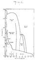
- Figure 1 is a phase diagram of a ternary system of sodium stearate- sodium chloride-water at 90°C reprinted, with permission of the publisher from Kirk-Othmer "Encyclopedia of Chemical Technology", Vol. 21 (3d Ed. 1979), John Wiley & Sons, Inc.
- Figure 2 is a binary phase diagram for sodium palmitate - water reprinted, with permission of the publisher, from Kirk-Othmer "Encyclopedia of Chemical Technology", Vol. 21 (3 Ed. 1979), John Wiley & Sons, Inc.
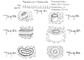
- Figure 3 illustrates the microstructural arrangements in lyotropic systems of mesomorphic or amphiphilic molecules having a spherical or lamellar configuration reprinted, with permission of the author and publisher, from G. H. Brown and J. J. Walken, "Liquid Crystals and Biological Structure", 1979 Academic Press, Inc.
- Figure 4 illustrates the variation of the real component of the dielectric constant E' with temperature for samples of solid bar soaps having a 10% wt. and 15% water content as set forth in Example I.
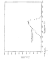
- Figure 5 illustrates on an expanded scale the variation of the real component of the dielectric constant E' with temperature for samples of solid bar soaps having a 10% wt. and 15% wt. water content as set forth in Example I.
- Figure 6 illustrates the variation of the real component of the dielectric constant E' with temperature for samples of solid bar soaps having a 10% wt. and 15% wt. water content as set forth in Example II.
- Figure 7 illustrates on an expanded scale the variation of the real component of the dielectric constant E' with temperature for a sample of solid bar soap having a 10% wt. water content as set forth in Example II.
- Figure 8 illustrates on an expanded scale the variation of the real component of the dielectric constant E' with temperature for solid bar soap having a 10% wt. and 15% wt. water content as set forth in Example II.
- Figure 9 illustrates the variation of the real component of the dielectric constant E' with temperature for solid bar soap A as set forth in Example III.
- Figure 10 illustrates the variation of the real component of the dielectric constant E' of solid bar soap with temperature as set forth in Example IV.
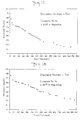
- Figure 11 illustrates the relative variation of the real component of the dielectric constant E' of 10% wt. water solid bar soaps with temperature as set forth in Examples I and II.
- Figure 12 illustrates the relative variation of the real component of the dielectric constant E' of 15% wt. water solid bar soap with temperature as set forth in Examples I and II.
- FIG. 13 illustrates an electrical storage device in accordance with the present invention.
- Figure 14 is a schematic of the circuit used to measure the variation of the discharge voltage of the storage device of the present invention over time.
- Figure 15 illustrates the variation of the discharge voltage of the storage device described in Example V wherein a solid bar soap was employed as the dielectric.
- Figures 16 to 19 illustrate the variation of the voltage of the storage devices of Examples VI to IX employing solid bar soap A as a function of time.
- Figures. 20-21 illustrate the variation of the voltage of the storage devices of Examples X and XI for various levels of charge and size of discharge loads.
- Figure 22 illustrates the variation of the voltage of the storage device of Fig. 13 as set forth in Example XII.
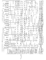
- Figure 23 is a table illustrating the fatty acid distribution in common fatty acid source materials.
- Figure 24 shows an electrical circuit used for determining the electrical characteristics of various nonisotropic solutions as set forth in Examples XIV-XXVIII.
- Figure 25 illustrates the temperature dependence of capacitance of a super capacitor constructed in accordance with this invention.
- Figure 26 illustrates a battery constructed in accordance with this invention.
- amphiphatic compounds used in the practice of this invention include molecules having a polar or hydrophilic end and non-polar or hydrophobic end and each of these ends is large enough to display its own solubility behavior in the liquids as hereinafter described.
- the amphiphatic compounds are known to orient themselves in polar liquids so that their nonpolar ends (e.g., the hydrocarbon portion of a soap molecule) dissolve in one another while their polar ends (e.g., the -COO- groups) project outwardly into the polar solvent thus exhibiting a controlled preference in orientation that produces liquid crystals. This orientation is reversed in non-polar solvents, Morrison and Boyd, Organic Chemistry, Chpt. 33 (3d Ed.
- Preferred amphiphatic compounds for use in this invention include salts of fatty acids, such as, alkali metal salts, alkaline earth metal salts, ammonium salts and alkanolammonium salts, more particularly sodium, lithium, potassium rubidium and cesium salts.
- These preferred fatty acid salts may include a saturated or unsaturated aliphatic moiety of about 6 to 18 carbon atoms, for example, sodium oleate, stearate or palmitate.
- the most preferred fatty acid salts are commercial soaps which are typically mixtures of the sodium salts of fatty acids of even carbon number ranging from about 12 to 18 carbons.
- Commercial soaps may be made by well known methods such as the hydrolysis of saponifiable fats, grease and oils such as, tallow and other animal fats; cottonseed oil and other vegetable oils and fats; fish oils, rosin and other resinous substances; and coconut oil, palm kernel oil, babassu oil, palm oil, olive oil, tall oil, castor oil, groundnut oil, linseed oil and hydrogeneated versions of these fats and oils.
- the fatty acid content of useful fatty acid source materials are listed in Figure 23.
- Conventional soap making processes are described in U.S. Patent Nos. 2,037,006; 2,190,592; 2,336,893; 3,793,215; 3,296,829; 4,201,743 and 4,490,280. However, as illustrated below simple soap systems have also been found to be effective.
- a kettle process for the preparation of neat soap is described in U.S. Patent No. 3,928,829. Briefly, the steps in preparing a neat soap are 1) the “killing or saponification stage" in which an aqueous solution of fatty acid source material, e.g., a 75/25 mixture of tallow and coconut oil, is heated with caustic, e.g., sodium hydroxide, to convert a substantial portion of the fatty acids to their salts; 2) the "change stage” in which the fatty acid salts are precipitated out of the solution; and 3) the "fitting stage” in which the neat soap phase (that is, the portion of the mixture that has a lamellar liquid crystal microstructure) is removed from the neat phase.
- neat soap may be made by other soap making processes well known to those skilled in the art.
- the liquid in the polarizable material is provided in sufficient quantity and selected to enable the amphiphatic compounds to organize into the desired liquid crystal microstructure.
- the preferred liquid components are polar liquids, particularly water.
- the liquid component should also solubilize any electrolyte included in the polarizable material.
- the preferred neat soaps include about 50 to 100% wt. fatty acid salts which may be derived from any fatty acid salt source material; about 10 to 30% wt. water and about 0 to 4% wt. sodium chloride more preferably about 0.3 to 1.2% wt. sodium chloride. However, the electrolyte may be excluded altogether.
- Useful fatty acid salt source materials are listed above and typically fatty acid distributions for such source materials are summarized in Fig. 23.
- the fatty acid source materials may be used alone or in various combinations to adjust the constituent fatty acid salts in the soap, e.g., 25% wt. tallow and 75% wt. coconut; 60% wt. tallow and 40% wt. coconut; or 85% wt. tallow and 15% wt. coconut.
- orientational associations of molecules in liquid crystal microstructures are extraordinarily sensitive to external perturbations and that changes in temperature, pressure and electrical and magnetic fields may cause significant changes in the long range order of the molecules.
- Solid bar soaps are usually prepared from neat soap by drying; reducing the size of the dry material by chipping, chopping, or the like; mixing the dry particles with no more than about 20% wt., and preferably less than about 2% wt., of additives such as fragrance, colorants, emmolients, antibacterials, preservatives and the like; and shaping the mixture into bars or some other desired shape usually by extrusion.
- additives such as fragrance, colorants, emmolients, antibacterials, preservatives and the like.
- the smectic lamellar microstructure that characterizes neat soaps is changed, primarily by mechanical forces, during preparation of solid bar soap, temperature and moisture.
- the solid bar soap microstructure is characterized by an interlocked mesh of fiber bundles of varying diameters and different degrees of twist but with a general tendency toward retaining both a criss-cross and a parallel structure.
- the microstructure of solid bar soap is referred to herein as 'bar phase' microstructure.
- neat soaps may also be cooled to form polymorphic micellar solid solutions.
- Specific solid solutions are recited in Examples XIV-XXVIII.
- the electrolyte employed in this invention may be a simple ionic salt such as sodium chloride and may be present either as an impurity from the process of making the amphiphatic compound or as an additive derived from some other source.
- the quantity of electrolyte should not exceed the amount at which the electrical resistance of the material becomes less than the amount at which the neat phase microstructure is disrupted, e.g., in commercial soaps more than about 4% wt. NaCl disrupts the neat phase.
- the salt content is at least about 0.1% wt.
- the amphiphatic compounds and liquid are combined in the necessary compositional amounts to produce the desired microstructure structure in the nonisotropic region.
- the necessary compositional amounts may be determined by locating the neat phase region on the McBain phase diagrams.
- McBain's phase diagrams of binary and ternary systems of soap-water and soap-salt-water appears in Kirk-Othmer "Encyclopedia of Chemical Technology", Vol. 21, pp. 166-170 (3d Ed. 1980).
- the phase behavior of the polar liquid, and amphiphatic components of soap in the neat phase appear to enhance the polarizable material's electric properties.
- Figure 1 illustrates a ternary system of sodium stearate, sodium chloride and water at 90°C.
- Figure 2 illustrates a binary system of sodium palmitate and water.
- the nonisotropic solution can take on various microstructures including neat, subneat, superwaxy, waxy, subwaxy and middle soaps.
- the nonisotropic solution could also be a polymorphic solic micellar solution identified as supercurd, dry and wet curd.
- Comparison of Figs. 1 and 2 illustrates that a system comprised of approximately 70% soap and 30% water and only a residual amount of salt (e.g., less that 0.5% wt.) falls within the neat phase structural range or region.
- a notable property of soap in the neat phase is the solid-like consistency of the system, i.e., it may be readily manufactured in bar, flake or bead form.
- a heretofore unappreciated property of such solid-like systems in the neat phase is an unexpectedly high dielectric constant.
- other nonisotropic solutions also have unexpectedly advantageous electrical properties.
- Another unappreciated property of such systems is their ability to generate electric current when used with two dissimilar electrodes.
- dielectric constant (E) of the nonistropic material with temperature have been observed and their dielectric properties have shown sensitivity to fatty acid salt and water concentration.
- the large dielectric constants of these liquid crystal materials is believed to be associated with some structural phase transition of a ferroelectric type.
- Ferroelectric compositions exhibit a phase showing a twin or domain structure in which individual domain states may be reoriented by applied electric fields and they may also be responsive to magnetic and elastic stress fields and various combinations thereof.
- the microstructures of the composition may be characterized as a liquid crystal microstructure.
- liquid crystal and “mesomorphic” may be used to describe physical properties of the materials because these materials exhibit a dualism of physical state, i.e., both solid and liquid behavior.
- the liquid crystalline behavior of amphipatic compounds is discussed in Kirk-Othmer “Encyclopedia of Chemical Technology", Vol. 14, pp. 395-427 (3d Ed. 1980). These properties are believed to be dictated or derived from orientational ordering of the constituent molecules of the materials in response to the liquid which impart the solid-like properties to the materials although these attractive and ordering forces are insufficient to totally exclude liquid properties.
- the liquid crystal material is lyotropic in the sense that it is a multicomponent system and the ordering/orientating, e.g., formation of lamellar, bar phase, micelle or other microstructures, by the constituent molecules (amphiphatic compound) results from the action of the liquid (water).
- the dielectric constants of bulk samples of various commercially available solid bar soaps were tested for the variation of their dielectric constant over temperature. In the examples which follow these samples will be referred to by their registered trademarks. Palmolive®, Irish Spring®, and Cashmere Bouquet® are registered trademarks of the Colgate Palmolive Company.
- the dielectric constants of Palmolive®, Irish Spring® (superfatted), Cashmere Bouquet® and standard brand commercially available solid bar soap hereinafter referred to as soap A were measured at a frequency of 1kBZ over a temperature range from 21°C to 160°C. Very strong temperature variations in the real component of the complex dielectric constant E' were observed at temperatures ranging from about 10°C to 130°C depending on the composition of the solid bar soap.
- a General Radio 1311-A oscillator set at 1kHZ was used to drive the bridge.
- a Princeton Applied Research HR-8 amplifier sensitive to phase was used as a null detector to balance the bridge.
- the mounted sample was placed in a stainless steel thermos and heated by resistive heaters directly connected to the electrodes. The temperature was measured with chrome-aluminum thermocouples attached to the electrodes. Heating rates were approximately 2°C per minute. Samples were checked for water loss by weighing before and after heating, and showed negligible weight loss (less than 0.1% wt.) which occurred mostly along the edges of the samples which were outside the central 3,81 cm (1-1/2") electrode which was used for measurement in the three electrode technique.
- Capacitance values were measured using the in-phase component and the out-of-phase component of the dielectric response. At temperatures above 80°C the capacitance typically would exceed the upper range of the bridge (I Farad) and so external resistors were added to the circuit. With external resistors the mutual conductance could not be balanced and consequently imaginary parts of the dielectric constant could not be measured. From the primary capacitance measurements, the real component of the dielectric constant E' was calculated using the thicknesses 0.95 cm (3/8 inch) of the sample and the central electrode area. No attempt was made to correct for possible electrode fringe effects. Subsequent d.c. measurements between the electrodes showed a resistance in the hundreds of megohms at room temperature. High d.c.
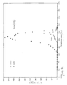
- Figs. 4 and 5 illustrate the variation of the real component of the dielectric constant E' with temperatures for Irish Spring® (superfatted) 10% wt. and 15% wt. water solid bar soaps. The appearance of the very narrow and very strong peak at 118°C in the 10% wt. water sample strongly suggests a structural phase transition of the sort observed in ferroelectric materials at their critical temperature.
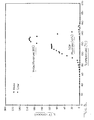
- Fig. 6 illustrates the variation of the real component of the dielectric constant E' with temperature for Palmolive® 15% wt. water soap and Palmolive® 10% wt. water bar soap.
- An expanded scale illustration of the variation of E' with temperature for low moisture (10% wt. water) Palmolive® solid bar soap is depicted in Fig. 7.
- Fig. 7 peaks occur at 118°C and 150°C and the E' values observed were higher than those observed in the testing of the Irish Spring® solid bar soaps described in Example I. It may also be observed by comparison of Figs. 6 and 7 that changes in the solid bar soap moisture content shifted the temperature location of the E' peaks.
- Figure 8 provides an expanded scale comparison of the dielectric constant of the 10% wt. water and 15% wt. water Palmolive® solid bar soaps with temperature.
- Figs. 11 and 12 illustrate the relative variation of the real component of the dielectric constants of 10% wt. water and 15% wt. water Irish Spring® solid bar soap and Palmolive® solid bar soap with temperature based upon the experiments described in Examples I-IV.
- Palmolive Gold® solid bar soap was used as a dielectric in an electrical energy storage device made from single sided copper circuit board 6,35 cm x 9,53 cm (2 1/2 inch by 3 3/4 inch) with a 0,32 cm (1/8 inch) thickness of solid bar soap therebetween. Five such devices were connected in parallel and charged with 9 volts and their discharge measured through a 2.35 megaohm resistor. The resulting data is summarized in Fig. 15.
- Soap A solid bar soap was substituted as the dielectric in the storage device of Example V.
- the device was charged using a 9 volt power source for eight minutes and electrical discharge was measured through a 2.35 megaohm resistor. Discharge voltage as a function of time was recorded and is illustrated in Fig. 16.
- Example VI The storage device of Example VI was charged for 15 minutes to 9 volts at a temperature of 19°C and subsequently discharged through a 2.35 megaohms resistor. The discharge voltage as a function of time was recorded and is illustrated in Fig. 17.
- Example VI The storage device described in Example VI were charged to 9 volts for 31 minutes and then discharged through 2.35 megaohms resistor. The discharge voltage as a function of time was recorded and is illustrated in Fig. 18.
- Example VI The storage device of Example VI was charged for 26 minutes to 9 volts. Soap A was employed as the dielectric. The device was then discharged through a resistance of 6.2 megaohms. The discharge voltage as a function of time is illustrated in Fig. 19.
- Irish Spring® solid bar soap was substituted as dielectric in the electric storage device described in Example V.
- the device was charged for 15 minutes to 9 volts at 22°C and discharged through a 2.35 megaohm resistor.
- the discharge voltage as a function of time was recorded and is illustrated in Fig. 20.
- Example V The storage device described in Example V was charged for a period of 30 minutes to 9 volts at 23°C and then discharged through a 2.35 megaohm resistor. Irish Spring® solid bar soap was used as the dielectric and the discharge voltage as a function of time was recorded and illustrated in Fig. 21.
- Individual capacitors (1) were constructed from commercial metal foil 2 such as aluminum foil and sterile gauze fabric impregnated with neat soap 3, as shown in Figure 13.
- the gauze employed provided both structural support for the neat soap and served to space the metal foil electrodes 2.
- the neat soap utilized in these capacitors was prepared from a blend of edible tallow and coconut oil, according to conventional batch methods. A tallow/coconut oil ratio of 75/25 (by weight) was employed.
- Each capacitor contained a total of 10 foil electrodes separated by 9 layers of gauze impregnated with neat soap.
- Each aluminum foil electrode had a surface area of 161,29 cm (25 square inches).
- the carbon chain distribution of the neat soap used in these capacitors is shown in Table 1. The moisture content of the neat soap was determined to be 25%.
- Example XII The storage device described in Example XII was charged to 9 volts for a period of 43 minutes. The device was then connected to a d.c. motor which ran for a total of 8 minutes. During the discharge of the device, the motor initially spun rapidly for two to three minutes with no apparent loss of speed and thereafter noticeably slowed.
- the device was reconnected to the 9 volt power source and was recharged for a period of 7 minutes.
- the storage device was then connected to the d.c. motor and allowed to discharge.
- the d.c. motor which was connected to a paper pin wheel and ran for approximately 7 minutes and 55 seconds.
- the storage device was once again recharged to 9 volts for a period of 9 minutes and reconnected to the motor.
- the storage device powered the motor for 13 minutes. This procedure was repeated for a charge period of 11 minutes.
- the storage device powered the motor for approximately 5 minutes.
- Example XII The storage device described in Example XII was charged for a period of 10 minutes to 8.68 volts. The device was then discharged through a motor which had a resistance of 20.8 ohms. Subsequent to the discharge, the device was left in a quiescent state whereupon it displayed a hysteresis effect of recharging from about 0.2V to about 1.2V in a few minutes. This hysteresis effect indicates that the storage device of the present invention exhibits a recharging capability such as that possessed by batteries.
- Fig. 22 illustrates the discharge and hysteresis effect as a function of time.
- the circuit includes a supercapacitor 100 disposed in an oven 102 for temperature control.
- the supercapacitor is first charged from a battery through a SPPT switch.
- the device is discharged by throwing switch 106 into the discharge position.
- the load on the supercapacitor is selected by a load select switch 108.
- a third switch 110 is opened.
- the voltage across the super capacitor is measured at test point 112. This voltage may also be monitored by other instruments such as a storage scope through a preamp 116.
- the test supercapacitor 100 was of the parallel plate type, using 3.25 cm diameter circular stainless steel disks as electrodes. Sample spacing was controlled by using a thin spacer of cellulose acetate between the electrodes. Samples were prepared by depositing a thin coating of the solid soap to the electrodes, placing the electrodes into a hydraulic press and using a heat gun to soften the soap. Pressure was then applied to the electrodes. Heat shrink tubing was applied to the electrode edges to prevent moisture evaporation.
- the sample was then transferred to oven 102 for DC capacitance measurements. High temperature measurements were completed first. The sample was allowed to equilibrate at the lamellar liquid crystal phase for approximately two hours before measurements were made.
- a one volt potential was applied to the sample for a one hour period. Leakage current was measured at 1, 2, 3, 5, 10, 30, and 60 minutes. After this one hour charging cycle, the sample was discharged through a 10K ohm resistor. The capacitance was calculated from the time required for the potential across the capacitor to reach 36.8% of the charging potential, i.e., by measuring the time constant of the circuit.
- the sample was then recharged until the leakage current was equal to the 60 minute leakage current obtained during the first charging cycle.
- the capacitor was then discharged through a 100K ohm resistor.
- a third charge cycle was begun, terminating when the leakage current was equal to the 60 minute leakage current obtained during the first charging cycle, and the self-discharge was measured.
- the sample was then slowly cooled to room temperature under a 10K ohm resistive load and the procedure was repeated.
- the samples used in this study included commercial Colgate Palmolive® neat soap consisting of a blend of 75/25% tallow and coconut oil, and high purity anhydrous soaps.
- the anhydrous soaps were mixed with 30 weight percent deuterated water. For each soap the temperature was raised to the isotropic solution temperature. The samples were then brought to the lamellar liquid crystal neat soap region of the phase diagram and quenched to room temperature.
- the capacitance was determined by the discharge RC time constant using a 1K ohm resistor. The capacitance increases with increasing temperature. Data is summarized in Fig. 25. In the case of the Colgate Palmolive® neat soap containing .3% NaCl, the capacitance did not appear to be a function of sample thickness and varied only with surface area of the electrodes. This behavior matches the behavior of supercapacitors. The data shows a significant improvement of the supercapacitors described in the above mentioned literature when compared in parallel plate configurations.
- the battery cell 200 includes two plates 202, 204 separated by a fiberglass mesh screen 206.
- the mesh had a thickness of 0.025 cm, and is impregnated with an electrolyte 208 consisting of the neat soap.
- One electrode was made of #316 stainless steel foil, while the other electrode was made of aluminum foil.
- Three such battery cells having 6.25 cm electrodes were connected in parallel. The three battery cells in parallel generated over 1 volt, without any external charging.
- the battery cells When disconnected from the resistive load, the battery cells rejuvenated themselves to a potential 1.1 volts within three minutes.
- a second battery cell was made using 9.6 cm electrodes of #316 stainless steel foil and aluminum foil, with an electrolyte of Colgate Palmolive® neat soap with 0.3% NaCl impregnating a fiberglass spacer.
- the potential across the battery cell was 1.3 volts.
- the current versus time discharge characteristics under a load of 10Kohm was as follows: Current (microamps) Time (seconds) Starting potential 1.335 volts 0 128.5 1 110.5 10 94 100 83.5 1000 75 3000 72 4000 68.5 8000
- the cells were left undisturbed for approximately 15 hours and again discharged through a 100 ohm resistor.
- the following current versus time characteristic was obtained: Current (microamps) Time (seconds) Starting potential of 1.13 volts 0 6500 1 4100 10 1050 100 250 400
- the two cells in parallel under a resistive load of 100 ohms delivered a constant .400 milliamp current.
Landscapes
- Engineering & Computer Science (AREA)
- Power Engineering (AREA)
- Chemical & Material Sciences (AREA)
- Chemical Kinetics & Catalysis (AREA)
- Electrochemistry (AREA)
- Manufacturing & Machinery (AREA)
- General Chemical & Material Sciences (AREA)
- Microelectronics & Electronic Packaging (AREA)
- Electric Double-Layer Capacitors Or The Like (AREA)
- Fixed Capacitors And Capacitor Manufacturing Machines (AREA)
- Primary Cells (AREA)
- Liquid Crystal Substances (AREA)
- Pharmaceuticals Containing Other Organic And Inorganic Compounds (AREA)
- Medicinal Preparation (AREA)
- Detergent Compositions (AREA)
- Medicines Containing Material From Animals Or Micro-Organisms (AREA)
- Acyclic And Carbocyclic Compounds In Medicinal Compositions (AREA)
- Cosmetics (AREA)
Abstract
Description
- This invention relates generally to electrical devices using a polarizable material including nonisotropic solution and comprised of one or more amphiphatic compounds. The solution has a liquid crystal microstructure. More specifically, this invention relates to a nonisotropic solution having an ordered structure which makes it useful in the manufacture of electrical storage devices, batteries, and capacitors.
- An embodiment of this invention may be a parallel plate supercapacitor or an electrochemical primary battery that can be charged and discharged comprised of a nonisotropic solution such as a neat solid or solid bar phase soap dielectric disposed between conducting electrodes.
- Various electrical properties of organic materials such as waxes and resins have been disclosed in the prior art. In U.S. Patent No. 1,952,158 issued to Clark et al. a colloidal gel is disclosed which remains plastic and stable at temperatures as low as -20°C and as high as 110°C and which comprises mineral oil and a small proportion of metallic soap as a dielectric material. Clark et al. disclose that when 2 to 12% wt. of metallic soap is added to approximately 90% wt. of mineral oil, a colloidal gel is formed which functions as a dielectric.
- U.S. Patent No. 1,576,096, issued to Davey discloses the use of purified glycerides, essentially water free unsaturated fatty acids or the various soaps of the fatty acids in conjunction with a cellulose paper, as the dielectric material in capacitors. Davey attributes enhancement of the dielectric behavior of the cellulose paper to the addition of the purified glycerides. The essentially water-free unsaturated fatty acids or the various soaps of the fatty acids disclosed by Davy are believed to entrap residual water molecules on the surface of the cellulose paper so that the water does not contribute to the conductivity of the paper.
- Methods for producing electrets from molten wax and wax-like materials solidified in an electric field are well known in the art. See U.S. Patents Nos. 1,804,364; 1,886,235; 2,024,705; 2,986,524; 2,284,039 and 2,460,109. Electrets are quasi-permanent charged dielectric materials useful as tranducers in microphones, earphones, phonograph cartridges and the like.
- U.S. Patent No. 3,301,786, issued to Klass discloses a synthetic ferroelectric article comprised of a dispersion of a solid silica compound in an organic vehicle such as a polyoxyalkylene, paraffin wax, microcrystalline wax or polypropylene. lass induces permanent electret properties on the opposite sides of his dispersion by subjecting a melted slab thereof to D.C. current during cooling.
- U.S. Patent No. 3,458,713, issued to Pearlman et al., discloses an electret comprised of a high molecular weight polycyclic bisphenol polycarbonate which has been permanently electrostatically polarized. Pearlman et al. disclose that such compounds retain electric charge for long periods of time, e.g., ten years.
- U.S. Patent No. 2,916,792, issued to Crook, et al. discloses an apparatus and method for controlling the rate of extrusion of soap bars by passing the soap bars which have a dielectric constant higher than air between the electrodes of a detecting capacitor and measuring changes in the capacitance thereof.
- The electronic industry is striving to develop electrical devices which perform very complex functions but occupy a very small space. Recently, a new line of devices have been developed which have found a wide range of applications for which a relatively low voltage power source is required for extended time periods. These devices are known as electric double-layer capacitors, or supercapacitors, and are described in detail in the following articles:
- A.J. Juodikis "Supercapacitors Serve As Standby Power Sources", Electronic Design, September 30, 1982, pp 159-164;
- K. Sanada and M. Hosokawa, "Electric Double Layer Capacitor 'Super Capacitor'", NEC Research & Development No. 55 (October, 1979) pp. 21-27; and
- K. Inada, "Super Capacitor Works As A Power Backup For Microcomponents", Journal of Electronic Engineering, November 1982, pp. 32-37.
- These references disclose a double-layer capacitor comprising two phases in contact, one phase including, for example, activated carbon, and the second phase including for example a sulfuric acid solution, or a liquid organic electrolyte.
- It can be seen from the foregoing prior art references that there is an ongoing effort to fill the need for materials having desirable electrical properties particularly, high dielectric constants and good capacitance and that can be easily and economically produced.
- U.S. Patent No. 1 951 720 of Bergstein is directed to an electrolytic capacitor comprising a first aluminum electrode (or anode) coated with a dielectric film (i. e. aluminum oxide), and a second electrode comprising an electrolyte and an aluminum cathode. The electrolyte comprises a mixture of ammonium linoleate, stearic acid and (optionally) oleic acid.
- It is an object of the present invention to provide a polarizable material comprising a nonisotropic solution comprised of an amphiphatic compound and a liquid.
- It is a further object of the present invention to provide a primary battery with a nonisotropic solution as an electrolyte.
- It is a further objective of the invention to provide a super capacitor which includes a nonisotropic solution as an electrolyte.
- It is a further objective of the invention to provide a super capacitor having a very high capacitance.
- It is a further objective of the invention to provide a super capacitor having a small area and volume as compared to prior art devices and which is operative at high temperatures.
- In accordance with the aforementioned objects the present invention provides an electrical storage device as claimed in
claim 1. - The present invention also provides a capacitor as claimed in
claim 2. - The present invention further provides a battery as claimed in
claim 3. - The preferred amphipathic compounds are salts of a fatty acids and preferably selected from a group consisting of alkaline metal, alkaline earth metal, ammonium and alkanol-ammonium salts of the fatty acids. The preferred liquid is water or heavy water and may further include a electrolyte such as a soluble ionic salt, e.g., NaCl.
- The amphipathic compounds described above at relatively high temperatures form various phases of neat soaps and have various liquid crystal microstructures. When these compounds are cooled polymorphic solid micellar solutions are obtained. It was found that the amphipathic compounds have desirable electrical properties in either the liquid crystal microstructure or the polymorphic solid micellar solution state. The term nonisotropic solution includes amphipathic compounds in both states. Furthermore, solid micellar solutions may have advantageous electrical properties, such as a high dielectric constant even if they were not formed by cooling an amphipathic compound having a liquid crystal microstructure such as a neat soap.
- The polarizable materials of the present invention having necessary microstructure may be a simple binary mixture of an amphipathic compound and a liquid in appropriate quantities.
- It has been discovered that the nonisotropic solution of the present invention may be utilized as a dielectric in a parallel plate capacitor device. The device may be charged with a DC current and the charged device discharges in response to a load at first quickly in a manner that would be expected for a capacitor and then more slowly in a manner that would be expected for a storage battery. Interestingly, the electrical potential of the device is not instantaneously discharged by shorting and restores itself when the load is removed due to the high dielectric absorption of the material.
- It has been further discovered that a primary battery, i.e., a battery which needs no initial charging is obtained when such a nonisotropic solution is used as an electrolyte disposed between two dissimilar electrodes.
- The various properties and characteristics of the present invention will now be further illustrated and better understood by reference to the following drawings.
- Figure 1 is a phase diagram of a ternary system of sodium stearate- sodium chloride-water at 90°C reprinted, with permission of the publisher from Kirk-Othmer "Encyclopedia of Chemical Technology", Vol. 21 (3d Ed. 1979), John Wiley & Sons, Inc.
- Figure 2 is a binary phase diagram for sodium palmitate - water reprinted, with permission of the publisher, from Kirk-Othmer "Encyclopedia of Chemical Technology", Vol. 21 (3 Ed. 1979), John Wiley & Sons, Inc.
- Figure 3 illustrates the microstructural arrangements in lyotropic systems of mesomorphic or amphiphilic molecules having a spherical or lamellar configuration reprinted, with permission of the author and publisher, from G. H. Brown and J. J. Walken, "Liquid Crystals and Biological Structure", 1979 Academic Press, Inc.
- Figure 4 illustrates the variation of the real component of the dielectric constant E' with temperature for samples of solid bar soaps having a 10% wt. and 15% water content as set forth in Example I.
- Figure 5. illustrates on an expanded scale the variation of the real component of the dielectric constant E' with temperature for samples of solid bar soaps having a 10% wt. and 15% wt. water content as set forth in Example I.
- Figure 6 illustrates the variation of the real component of the dielectric constant E' with temperature for samples of solid bar soaps having a 10% wt. and 15% wt. water content as set forth in Example II.
- Figure 7 illustrates on an expanded scale the variation of the real component of the dielectric constant E' with temperature for a sample of solid bar soap having a 10% wt. water content as set forth in Example II.
- Figure 8 illustrates on an expanded scale the variation of the real component of the dielectric constant E' with temperature for solid bar soap having a 10% wt. and 15% wt. water content as set forth in Example II.
- Figure 9 illustrates the variation of the real component of the dielectric constant E' with temperature for solid bar soap A as set forth in Example III.
- Figure 10 illustrates the variation of the real component of the dielectric constant E' of solid bar soap with temperature as set forth in Example IV.
- Figure 11 illustrates the relative variation of the real component of the dielectric constant E' of 10% wt. water solid bar soaps with temperature as set forth in Examples I and II.
- Figure 12 illustrates the relative variation of the real component of the dielectric constant E' of 15% wt. water solid bar soap with temperature as set forth in Examples I and II.
- Figure 13 illustrates an electrical storage device in accordance with the present invention.
- Figure 14 is a schematic of the circuit used to measure the variation of the discharge voltage of the storage device of the present invention over time.
- Figure 15 illustrates the variation of the discharge voltage of the storage device described in Example V wherein a solid bar soap was employed as the dielectric.
- Figures 16 to 19 illustrate the variation of the voltage of the storage devices of Examples VI to IX employing solid bar soap A as a function of time.
- Figures. 20-21 illustrate the variation of the voltage of the storage devices of Examples X and XI for various levels of charge and size of discharge loads.
- Figure 22 illustrates the variation of the voltage of the storage device of Fig. 13 as set forth in Example XII.
- Figure 23 is a table illustrating the fatty acid distribution in common fatty acid source materials.
- Figure 24 shows an electrical circuit used for determining the electrical characteristics of various nonisotropic solutions as set forth in Examples XIV-XXVIII.
- Figure 25 illustrates the temperature dependence of capacitance of a super capacitor constructed in accordance with this invention.
- Figure 26 illustrates a battery constructed in accordance with this invention.
- The compositional nature and the electrical behavior of the materials used in the practice of the present invention will now be discussed in more detail.
- The amphiphatic compounds used in the practice of this invention include molecules having a polar or hydrophilic end and non-polar or hydrophobic end and each of these ends is large enough to display its own solubility behavior in the liquids as hereinafter described. The amphiphatic compounds are known to orient themselves in polar liquids so that their nonpolar ends (e.g., the hydrocarbon portion of a soap molecule) dissolve in one another while their polar ends (e.g., the -COO- groups) project outwardly into the polar solvent thus exhibiting a controlled preference in orientation that produces liquid crystals. This orientation is reversed in non-polar solvents, Morrison and Boyd, Organic Chemistry, Chpt. 33 (3d Ed. 1973); Kirk-Othmer "Encyclopedia of Chemical Technology" Vol. 14, p. 395 et seg.) (3d Ed. 1980). Preferred amphiphatic compounds for use in this invention include salts of fatty acids, such as, alkali metal salts, alkaline earth metal salts, ammonium salts and alkanolammonium salts, more particularly sodium, lithium, potassium rubidium and cesium salts. These preferred fatty acid salts may include a saturated or unsaturated aliphatic moiety of about 6 to 18 carbon atoms, for example, sodium oleate, stearate or palmitate.
- Presently, the most preferred fatty acid salts are commercial soaps which are typically mixtures of the sodium salts of fatty acids of even carbon number ranging from about 12 to 18 carbons. Commercial soaps may be made by well known methods such as the hydrolysis of saponifiable fats, grease and oils such as, tallow and other animal fats; cottonseed oil and other vegetable oils and fats; fish oils, rosin and other resinous substances; and coconut oil, palm kernel oil, babassu oil, palm oil, olive oil, tall oil, castor oil, groundnut oil, linseed oil and hydrogeneated versions of these fats and oils. The fatty acid content of useful fatty acid source materials are listed in Figure 23. Conventional soap making processes are described in U.S. Patent Nos. 2,037,006; 2,190,592; 2,336,893; 3,793,215; 3,296,829; 4,201,743 and 4,490,280. However, as illustrated below simple soap systems have also been found to be effective.
- A kettle process for the preparation of neat soap is described in U.S. Patent No. 3,928,829. Briefly, the steps in preparing a neat soap are 1) the "killing or saponification stage" in which an aqueous solution of fatty acid source material, e.g., a 75/25 mixture of tallow and coconut oil, is heated with caustic, e.g., sodium hydroxide, to convert a substantial portion of the fatty acids to their salts; 2) the "change stage" in which the fatty acid salts are precipitated out of the solution; and 3) the "fitting stage" in which the neat soap phase (that is, the portion of the mixture that has a lamellar liquid crystal microstructure) is removed from the neat phase. Of course, neat soap may be made by other soap making processes well known to those skilled in the art.
- It has also been found that commercially available solid soaps are useful in this invention, as illustrated in greater detail in the examples which follow.
- The liquid in the polarizable material is provided in sufficient quantity and selected to enable the amphiphatic compounds to organize into the desired liquid crystal microstructure. The preferred liquid components are polar liquids, particularly water. The liquid component should also solubilize any electrolyte included in the polarizable material.
- The preferred neat soaps include about 50 to 100% wt. fatty acid salts which may be derived from any fatty acid salt source material; about 10 to 30% wt. water and about 0 to 4% wt. sodium chloride more preferably about 0.3 to 1.2% wt. sodium chloride. However, the electrolyte may be excluded altogether. Useful fatty acid salt source materials are listed above and typically fatty acid distributions for such source materials are summarized in Fig. 23. The fatty acid source materials may be used alone or in various combinations to adjust the constituent fatty acid salts in the soap, e.g., 25% wt. tallow and 75% wt. coconut; 60% wt. tallow and 40% wt. coconut; or 85% wt. tallow and 15% wt. coconut.
- It will be appreciated by those skilled in the art that the orientational associations of molecules in liquid crystal microstructures, such as neat soaps, are extraordinarily sensitive to external perturbations and that changes in temperature, pressure and electrical and magnetic fields may cause significant changes in the long range order of the molecules.
- Solid bar soaps are usually prepared from neat soap by drying; reducing the size of the dry material by chipping, chopping, or the like; mixing the dry particles with no more than about 20% wt., and preferably less than about 2% wt., of additives such as fragrance, colorants, emmolients, antibacterials, preservatives and the like; and shaping the mixture into bars or some other desired shape usually by extrusion. The smectic lamellar microstructure that characterizes neat soaps is changed, primarily by mechanical forces, during preparation of solid bar soap, temperature and moisture. The solid bar soap microstructure is characterized by an interlocked mesh of fiber bundles of varying diameters and different degrees of twist but with a general tendency toward retaining both a criss-cross and a parallel structure. The microstructure of solid bar soap is referred to herein as 'bar phase' microstructure.
- As previously mentioned, neat soaps may also be cooled to form polymorphic micellar solid solutions. Specific solid solutions are recited in Examples XIV-XXVIII.
- The electrolyte employed in this invention may be a simple ionic salt such as sodium chloride and may be present either as an impurity from the process of making the amphiphatic compound or as an additive derived from some other source. The quantity of electrolyte should not exceed the amount at which the electrical resistance of the material becomes less than the amount at which the neat phase microstructure is disrupted, e.g., in commercial soaps more than about 4% wt. NaCl disrupts the neat phase. Generally, the salt content is at least about 0.1% wt.
- The amphiphatic compounds and liquid are combined in the necessary compositional amounts to produce the desired microstructure structure in the nonisotropic region. For example, with commercial soaps the necessary compositional amounts may be determined by locating the neat phase region on the McBain phase diagrams. A discussion of McBain's phase diagrams of binary and ternary systems of soap-water and soap-salt-water appears in Kirk-Othmer "Encyclopedia of Chemical Technology", Vol. 21, pp. 166-170 (3d Ed. 1980). The phase behavior of the polar liquid, and amphiphatic components of soap in the neat phase appear to enhance the polarizable material's electric properties.
- Figure 1 illustrates a ternary system of sodium stearate, sodium chloride and water at 90°C. Figure 2 illustrates a binary system of sodium palmitate and water. As seen from Figure 2, the nonisotropic solution can take on various microstructures including neat, subneat, superwaxy, waxy, subwaxy and middle soaps. The nonisotropic solution could also be a polymorphic solic micellar solution identified as supercurd, dry and wet curd. Comparison of Figs. 1 and 2 illustrates that a system comprised of approximately 70% soap and 30% water and only a residual amount of salt (e.g., less that 0.5% wt.) falls within the neat phase structural range or region.
- A notable property of soap in the neat phase is the solid-like consistency of the system, i.e., it may be readily manufactured in bar, flake or bead form. A heretofore unappreciated property of such solid-like systems in the neat phase is an unexpectedly high dielectric constant. Furthermore, it was discovered that other nonisotropic solutions also have unexpectedly advantageous electrical properties. Another unappreciated property of such systems is their ability to generate electric current when used with two dissimilar electrodes.
- Large variations of the dielectric constant (E) of the nonistropic material with temperature have been observed and their dielectric properties have shown sensitivity to fatty acid salt and water concentration. Although not fully understood, the large dielectric constants of these liquid crystal materials is believed to be associated with some structural phase transition of a ferroelectric type. Ferroelectric compositions exhibit a phase showing a twin or domain structure in which individual domain states may be reoriented by applied electric fields and they may also be responsive to magnetic and elastic stress fields and various combinations thereof.
- It is also possible that the advantageous electrical properties of neat soaps result from a structural phase transition that affects e.g., the liquid crystalline lamellar or micelle microstructure illustrated in Figure 3 or the bar phase microstructure of solid bar soaps.
- The microstructures of the composition may be characterized as a liquid crystal microstructure. The terms "liquid crystal" and "mesomorphic" may be used to describe physical properties of the materials because these materials exhibit a dualism of physical state, i.e., both solid and liquid behavior. The liquid crystalline behavior of amphipatic compounds is discussed in Kirk-Othmer "Encyclopedia of Chemical Technology", Vol. 14, pp. 395-427 (3d Ed. 1980). These properties are believed to be dictated or derived from orientational ordering of the constituent molecules of the materials in response to the liquid which impart the solid-like properties to the materials although these attractive and ordering forces are insufficient to totally exclude liquid properties. The liquid crystal material is lyotropic in the sense that it is a multicomponent system and the ordering/orientating, e.g., formation of lamellar, bar phase, micelle or other microstructures, by the constituent molecules (amphiphatic compound) results from the action of the liquid (water).
- Detailed embodiments of the invention will now be described in the following examples.
- The dielectric constants of bulk samples of various commercially available solid bar soaps were tested for the variation of their dielectric constant over temperature. In the examples which follow these samples will be referred to by their registered trademarks. Palmolive®, Irish Spring®, and Cashmere Bouquet® are registered trademarks of the Colgate Palmolive Company. The dielectric constants of Palmolive®, Irish Spring® (superfatted), Cashmere Bouquet® and standard brand commercially available solid bar soap hereinafter referred to as soap A were measured at a frequency of 1kBZ over a temperature range from 21°C to 160°C. Very strong temperature variations in the real component of the complex dielectric constant E' were observed at temperatures ranging from about 10°C to 130°C depending on the composition of the solid bar soap. This variation was found to be dependent in part on the water content of the solid bar soap, for example, Irish Spring® (superfatted) solid bar soap with 10% wt. water showed an E' peak value of 1,488,000 at 118°C and Irish Spring®(superfatted) solid bar soap with a water content of 15% wt. had an E' peak value of 5,861,000 at 107°C. From these observations it was concluded that the dielectric constant exhibited strong sensitivity to the solid bar soap ccmposition and water concentration. As mentioned above the enormous increase in dielectric constant with temperature suggests a structural phase transition of a ferroelectric type. E' values were measured for the various bar soaps as follows.
- Samples of bar soap 0.95 cm (3/8") thick by 5,08 cm (2") wide by 7,62 cm (3") long were cut by milling and placed between two flat, parallel gold plated electrodes. The samples were clamped between the two gold plated capacitor electrodes and held in place with electrically insulating bolts so that the surfaces of the soap made good contact with the electrodes but did not plastically flow. The upper electrode was divided into a
circle 3,81 cm (1-1/2") in diameter and aguard ring - As illustrated in Figs. 4 and 5, the effect of water addition to the bar soap is to increase the dielectric constant so that at 27°C, E' = 52 K, and at 107°C, E' = 5,861,000. Figure 5 shows that even at 40°C there is nearly a tenfold difference between the the value of real component of the dielectric constant E' for the 10% wt. water solid soap bar sample and that of the 15% wt. water solid soap bar sample.
- The variation of the real component of the dielectric constant E' of Palmolive® solid bar soap with temperature was determined in accordance with the method described in Example I. Fig. 6 illustrates the variation of the real component of the dielectric constant E' with temperature for
Palmolive® 15% wt. water soap andPalmolive® 10% wt. water bar soap. An expanded scale illustration of the variation of E' with temperature for low moisture (10% wt. water) Palmolive® solid bar soap is depicted in Fig. 7. In Fig. 7 peaks occur at 118°C and 150°C and the E' values observed were higher than those observed in the testing of the Irish Spring® solid bar soaps described in Example I. It may also be observed by comparison of Figs. 6 and 7 that changes in the solid bar soap moisture content shifted the temperature location of the E' peaks. - Figure 8 provides an expanded scale comparison of the dielectric constant of the 10% wt. water and 15% wt. water Palmolive® solid bar soaps with temperature.
- The variation of the real component of the dielectric constant E' of solid bar soap A with temperature was determined in accordance with the method described in Example I. The values of the real component of the dielectric constant determined by this experiment are illustrated in Fig. 9.
- The variation of the real component of the dielectric constant E' of Cashmere Bouquet® solid bar soap with temperature was determined in accordance with the method described in Example I. The values of the real component of the dielectric constant determined by the experiment are illustrated in Figure 10.
- Figs. 11 and 12 illustrate the relative variation of the real component of the dielectric constants of 10% wt. water and 15% wt. water Irish Spring® solid bar soap and Palmolive® solid bar soap with temperature based upon the experiments described in Examples I-IV.
- Palmolive Gold® solid bar soap was used as a dielectric in an electrical energy storage device made from single sided
copper circuit board 6,35 cm x 9,53 cm (2 1/2 inch by 3 3/4 inch) with a 0,32 cm (1/8 inch) thickness of solid bar soap therebetween. Five such devices were connected in parallel and charged with 9 volts and their discharge measured through a 2.35 megaohm resistor. The resulting data is summarized in Fig. 15. - Soap A solid bar soap was substituted as the dielectric in the storage device of Example V. The device was charged using a 9 volt power source for eight minutes and electrical discharge was measured through a 2.35 megaohm resistor. Discharge voltage as a function of time was recorded and is illustrated in Fig. 16.
- The storage device of Example VI was charged for 15 minutes to 9 volts at a temperature of 19°C and subsequently discharged through a 2.35 megaohms resistor. The discharge voltage as a function of time was recorded and is illustrated in Fig. 17.
- The storage device described in Example VI were charged to 9 volts for 31 minutes and then discharged through 2.35 megaohms resistor. The discharge voltage as a function of time was recorded and is illustrated in Fig. 18.
- The storage device of Example VI was charged for 26 minutes to 9 volts. Soap A was employed as the dielectric. The device was then discharged through a resistance of 6.2 megaohms. The discharge voltage as a function of time is illustrated in Fig. 19.
- Irish Spring® solid bar soap was substituted as dielectric in the electric storage device described in Example V. The device was charged for 15 minutes to 9 volts at 22°C and discharged through a 2.35 megaohm resistor. The discharge voltage as a function of time was recorded and is illustrated in Fig. 20.
- The storage device described in Example V was charged for a period of 30 minutes to 9 volts at 23°C and then discharged through a 2.35 megaohm resistor. Irish Spring® solid bar soap was used as the dielectric and the discharge voltage as a function of time was recorded and illustrated in Fig. 21.
- Individual capacitors (1) were constructed from
commercial metal foil 2 such as aluminum foil and sterile gauze fabric impregnated withneat soap 3, as shown in Figure 13. The gauze employed provided both structural support for the neat soap and served to space themetal foil electrodes 2. The neat soap utilized in these capacitors was prepared from a blend of edible tallow and coconut oil, according to conventional batch methods. A tallow/coconut oil ratio of 75/25 (by weight) was employed. Each capacitor contained a total of 10 foil electrodes separated by 9 layers of gauze impregnated with neat soap. Each aluminum foil electrode had a surface area of 161,29 cm (25 square inches). The carbon chain distribution of the neat soap used in these capacitors is shown in Table 1. The moisture content of the neat soap was determined to be 25%. - Four electrical devices of the type shown in Figure 13 were constructed. Each capacitor was then wrapped and heat sealed in a moisture barrier polymer film to reduce moisture loss. Small perforations were made in the polymer film to facilitate necessary electrical connections to the capacitors. In view of the above-noted dependence of the electrical properties of the materials on moisture content means for preventing loss or gain of liquid from the materials during storage and use should be provided.
- The capacitors were then configured in a circuit according to the schematic depicted in Figure 14 and charged by a 9 volt d.c. voltage source by closing
switch 15.Switch 15 was then opened and switch 20 closed to permit measurement of the discharge voltage of thestorage devices 30 with aBechman 360 digital voltmeter acrossresistance 25. The discharge voltage was measured as a function of time.
Table 2 Capacitor Composition Details of construction of the capacitor of Example XII. Foil 7.5 grams 7.3 grams 7.7 grams 7.4 grams Gauze 6.9 grams 6.7 grams 6.8 grams 6.8 grams Soap 96.7 grams 88.9 grams 89.3 grams 79.4 grams Total 111.1 grams 112.9 grams 103.8 grams 93.6 grams - The storage device described in Example XII was charged to 9 volts for a period of 43 minutes. The device was then connected to a d.c. motor which ran for a total of 8 minutes. During the discharge of the device, the motor initially spun rapidly for two to three minutes with no apparent loss of speed and thereafter noticeably slowed.
- Approximately 58 minutes later, the device was reconnected to the 9 volt power source and was recharged for a period of 7 minutes. The storage device was then connected to the d.c. motor and allowed to discharge. The d.c. motor, which was connected to a paper pin wheel and ran for approximately 7 minutes and 55 seconds. The storage device was once again recharged to 9 volts for a period of 9 minutes and reconnected to the motor. The storage device powered the motor for 13 minutes. This procedure was repeated for a charge period of 11 minutes. The storage device powered the motor for approximately 5 minutes.
- The storage device described in Example XII was charged for a period of 10 minutes to 8.68 volts. The device was then discharged through a motor which had a resistance of 20.8 ohms. Subsequent to the discharge, the device was left in a quiescent state whereupon it displayed a hysteresis effect of recharging from about 0.2V to about 1.2V in a few minutes. This hysteresis effect indicates that the storage device of the present invention exhibits a recharging capability such as that possessed by batteries. Fig. 22 illustrates the discharge and hysteresis effect as a function of time.
- In order to determine whether nonisotropic solutions could be used as dielectrics in capacitors or as electrolytes in supercapacitors test devices were built and their DC parameters including capacitance, leakage current, and self-discharge rates were measured. The DC capacitance measurements have been performed at 1 volt using the circuit shown in Figure 24. The circuit includes a
supercapacitor 100 disposed in anoven 102 for temperature control. The supercapacitor is first charged from a battery through a SPPT switch. The device is discharged by throwingswitch 106 into the discharge position. The load on the supercapacitor is selected by a loadselect switch 108. To measure the self-discharge rate of the super capacitor, athird switch 110 is opened. The voltage across the super capacitor is measured attest point 112. This voltage may also be monitored by other instruments such as a storage scope through apreamp 116. - The
test supercapacitor 100 was of the parallel plate type, using 3.25 cm diameter circular stainless steel disks as electrodes. Sample spacing was controlled by using a thin spacer of cellulose acetate between the electrodes. Samples were prepared by depositing a thin coating of the solid soap to the electrodes, placing the electrodes into a hydraulic press and using a heat gun to soften the soap. Pressure was then applied to the electrodes. Heat shrink tubing was applied to the electrode edges to prevent moisture evaporation. - The sample was then transferred to
oven 102 for DC capacitance measurements. High temperature measurements were completed first. The sample was allowed to equilibrate at the lamellar liquid crystal phase for approximately two hours before measurements were made. - The following experimental procedure was used.
- A one volt potential was applied to the sample for a one hour period. Leakage current was measured at 1, 2, 3, 5, 10, 30, and 60 minutes. After this one hour charging cycle, the sample was discharged through a 10K ohm resistor. The capacitance was calculated from the time required for the potential across the capacitor to reach 36.8% of the charging potential, i.e., by measuring the time constant of the circuit.
- The sample was then recharged until the leakage current was equal to the 60 minute leakage current obtained during the first charging cycle. The capacitor was then discharged through a 100K ohm resistor. A third charge cycle was begun, terminating when the leakage current was equal to the 60 minute leakage current obtained during the first charging cycle, and the self-discharge was measured.
- The sample was then slowly cooled to room temperature under a 10K ohm resistive load and the procedure was repeated.
- The samples used in this study included commercial Colgate Palmolive® neat soap consisting of a blend of 75/25% tallow and coconut oil, and high purity anhydrous soaps. The anhydrous soaps were mixed with 30 weight percent deuterated water. For each soap the temperature was raised to the isotropic solution temperature. The samples were then brought to the lamellar liquid crystal neat soap region of the phase diagram and quenched to room temperature.
- The minimum lamellar phase temperature for each soap tested is provided below:
Soap Temperature (°C) Sodium Stearate 85-87 Potassium Stearate 60 Potassium Laurate Ambient Sodium Laurate 69-72 Sodium Palmitate 80-85°C Sodium Myristate 77-80°C - The DC capacitance measurements obtained for the tested nonisotropic solutions is listed in the following examples. In all these examples the current is given in microamps.
-
Soap: Potassium Stearate Temperature: 65°C Applied Voltage: 1 Volt Sample Thickness: 0.01 cm Surface Area of Electrodes: 4.453 cm Leakage Current Time (min) 36 1 31 2 28 3 24 5 18 10 8.6 30 4.7 60 -
DC capacitance - 10K ohm discharge 1,450 microFarads DC capacitance - 100K ohm discharge 3,190 microFarads -
Soap: Potassium Stearate Temperature: 25°C Applied Voltage: 1 Volt Sample Thickness: .01 cm Surface Area of Electrodes: 4.453 cm Leakage Current Time (min) 14.6 1 10 2 7.9 3 5.8 5 3.6 10 1.6 30 1.0 60 DC capacitance - 10K ohm discharge 563 microFarads DC capacitance - 100K ohm discharge 762 microFarads -
Voltage Time (min) .9953 0 .9437 1 .9127 2 .8878 3 .8669 4 .8489 5 .8330 6 .8188 7 .8059 8 .7941 9 .7834 10 .7066 20 .6584 30 -
Soap: Colgate Palmolive® Temperature: 80°C Neat Soap Applied Voltage: 1 Volt Sample Thickness: 0.01 cm Surface Area of Electrodes : 5.06 cm Leakage Current Time (min) 24.2 1 18.8 2 16.1 3 13.8 5 11.8 10 10.2 30 9.2 60 DC capacitance - 10K ohm discharge 3050 microFarads DC capacitance - 100K ohm discharge 2004 microFarads -
Voltage Time (min) .908 0 .699 1 .612 2 .546 3 .492 4 .445 5 .402 6 .364 7 .330 8 .301 9 .276 10 .129 20 .071 30 -
Soap: Colgate Palmolive® Neat Soap Temperature: 25°C Applied Voltage: 1 Volt Sample Thickness: 0.01 cm Surface Area of Electrodes: 5.06 cm Leakage Current Time (min) 8.7 1 2 4.6 3 3.7 5 2.8 10 1.9 30 1.7 60 DC cpacitance - 10K ohm discharge 620 microFarads DC capcitance - 100K ohm discharge 830 microFarads -
Voltage Time (min) .988 0 .845 1 .786 2 .745 5 -
Soap: Potassium Laurate Temperature: 25°C Applied Voltage: 1 Volt Sample Thickness: 0.005 cm Surface Area of Electrodes: 5.07 cm Leakage Current Time (min) 9.8 1 6.3 2 4.8 3 3.4 5 2.1 10 7.0 30 0.6 60 DC capacitance - 10K ohm discharge 530 microFarads DC capacitance - 100K ohm discharge 701 microFarads -
Voltage Time (min) .999 0 .962 1 .938 2 .919 3 .902 4 .888 5 .875 6 .863 7 .852 8 .842 9 .833 10 .764 20 .717 30 .681 40 -
Soap: Potassium Laurate Temperature: 40°C Applied Voltage: 1 Volt Sample Thickness: 0.005 cm Surface Area of Electrodes: 5.07 cm Leakage Current Time (min) 7.9 1 4.5 2 3.3 3 2.4 5 1.5 10 0.8 30 0.6 60 DC capacitance - 10K ohm discharge 554 microFarads DC capacitance - 100K ohm discharge 870 microFarads -
Voltage Time (min) .999 0 .958 1 .931 2 .910 3 .892 4 .877 5 .863 6 .851 7 .840 8 .829 9 .820 10 .753 20 .711 30 .680 40 .656 50 -
Soap: Sodium Laurate Temperature: 25°C Applied Voltage: 1 Volt Sample Thickness: 0.0125 cm Surface Area of Electrodes: 4.453 cm Leakage Current Time (min) 11.2 1 6.9 2 5.1 3 3.4 5 2.0 10 0.8 30 0.5 60 DC capacitance - 10K ohm discharge 566 microFarads DC capacitance - 100K ohm discharge 846 microFarads -
Voltage Time (min) .9712 1 .9530 2 .9380 3 .9250 4 .9134 5 .9031 6 .8936 7 .8849 8 .8768 9 .8693 10 .8132 20 .7758 30 .7475 40 .7248 50 -
Soap: Sodium Laurate Temperature: 81°C Applied Voltage: 1 Volt Sample Thickness: 0.0125 cm Surface Area of Electrodes: 4.453 cm Leakage Current Time (min) 33.1 1 26.0 2 22.0 3 18.0 5 12.4 10 6.6 30 4.4 60 DC capacitance - 10K ohm discharge 1,762 microFarads DC capacitance - 100K ohm discharge 2,520 microFarads -
Voltage Time (min) .9620 0 .8587 1 .7636 2 .7317 3 .7056 4 .6830 5 .6632 6 .6456 7 .6298 8 .6154 9 .5165 10 -
Soap: Sodium Stearate Temperature: 25°C Applied Voltage: 1 Volt Sample Thickness: 0.01 cm Surface Area of Electrodes: 4.453 cm Leakage Current Time (min) 3.5 1 2.1 2 1.6 3 1.1 5 0.7 10 0.4 30 0.3 60 DC capacitance - 10 K ohm discharge 222 microFarads DC capacitance - 100 K ohm discharge 402 microFarads -
Voltage Time (min) .9754 2 .9593 3 .9351 4 .9253 5 .9165 6 .9086 7 .9012 8 .8944 9 .8881 10 .8401 20 .8073 30 -
Soap: Sodium Stearate Temperature: 95°C Applied Voltage: 1 Volt Sample Thickness : 0.01 cm Surface Area of Electrodes: 4.453 cm Leakage Current Time (min) 25.8 1 18.8 2 14.8 3 10.2 5 5.9 10 3.4 30 2.8 60 DC capacitance - 10K ohm discharge 2,088 microFarads DC capacitance - 100K ohm discharge 3,014 microFarads -
Voltage Time (min) .9782 0 .9079 1 .8622 2 .8248 3 .7923 4 .7637 5 .7372 6 .7130 7 .6906 8 .6698 9 .6504 10 .5169 20 .4305 30 -
Soap: Sodium Myristate Temperature: 25°C Applied Voltage: 1 Volt Sample Thickness: 0.0125 cm Surface Area of Electrodes: 5.067 cm Leakage Current Time (min) 5.3 1 3.2 2 2.4 3 1.7 5 1.0 10 0.4 30 0.2 60 DC capacitance - 10K ohm discharge 298 microFarads DC capacitance - 100K ohm discharge 475 microFarads -
Voltage Time (min) .980 1 .966 2 .955 3 .945 4 .036 5 .929 6 .921 7 .915 8 .909 9 .903 10 .852 20 -
Soap: Sodium Myristate Temperature: 90°C Applied Voltage : 1 Volt Sample Thickness : 0.0125 cm Surface Area of Electrodes : 5.067 cm Leakage Current Time (min) 29.3 1 24.0 2 21.0 3 16.0 5 11.8 10 4.3 30 3.0 60 DC capacitance - 10K ohm discharge 1,092 microFarads DC capacitance - 100K ohm discharge 1,491 microFarads -
Voltage Time (min) .976 0 .881 1 .823 2 .777 3 .739 4 .707 5 .679 6 .655 7 .634 8 .616 9 .600 10 .497 20 .440 30 .401 40 -
Soap: Sodium Palmitate Temperature: 25°C Applied Voltage: 1 Volt Sample Thickness : .0075 cm Surface Area of Electrodes: 5.06 cm Leakage Current Time (min) 6.6 1 4.4 2 3.4 3 2.6 5 1.6 10 1.0 30 .8 60 DC capacitance - 10K ohm discharge 354 microFarads DC capacitance - 100K ohm discharge 809 microFarads -
Voltage Time (min) .9974 0 .9213 1 .8846 2 .8574 3 .8354 4 .8168 5 .8007 6 .7864 7 .7735 8 .7617 9 .7509 10 .2388 16 hours -
Soap: Sodium Palmitate Temperature: 88°C Applied Voltage: 1 Volt Sample Thickness: 0.0075 cm Surface Area of Electrodes: 5.067 cm Leakage Current (amp) Time (min) 21.7 1 16.0 2 13.2 3 10.2 5 7.2 10 3.9 30 2.5 60 DC capacitance - 10K ohm discharge 3116 microFarads DC capacitance - 100K ohm discharge 4892 microFarads -
Voltage Time (min) .917 1 .883 2 .856 3 .833 4 .813 5 .795 6 .779 7 .765 8 .751 9 .739 10 .643 20 .578 30 - Additional experiments were also performed with the Colgate Palmolive® neat soap as a function of temperature and applied voltage. Using electrodes of 3.3 cm in diameter and a sample thickness of 0.0125 cm, the following leakage currents were obtained after 30 minutes.
Temperature Voltage Leakage current Microamps 25 0.5 .2-.6 25 1.0 3.0-5.6 40 0.5 1.3 50 0.5 2.2 60 0.5 3.2 60 1.0 10.2 - The capacitance was determined by the discharge RC time constant using a 1K ohm resistor. The capacitance increases with increasing temperature. Data is summarized in Fig. 25. In the case of the Colgate Palmolive® neat soap containing .3% NaCl, the capacitance did not appear to be a function of sample thickness and varied only with surface area of the electrodes. This behavior matches the behavior of supercapacitors. The data shows a significant improvement of the supercapacitors described in the above mentioned literature when compared in parallel plate configurations.
- Surprisingly, using two dissimilar metal electrodes, for example, aluminum and stainless steel, separated by an electrolyte containing Colgate Palmolive® neat soap and 0.3% NaCl functioned as an electrochemical primary battery. Such a battery is shown in Fig. 26. The
battery cell 200 includes twoplates fiberglass mesh screen 206. The mesh had a thickness of 0.025 cm, and is impregnated with anelectrolyte 208 consisting of the neat soap. One electrode was made of #316 stainless steel foil, while the other electrode was made of aluminum foil. Three such battery cells having 6.25 cm electrodes were connected in parallel. The three battery cells in parallel generated over 1 volt, without any external charging. When discharged through a 10K ohm resistor for a period of 10 minutes, the following current flow was obtained from the three battery cells:Current (microamps) time (seconds) 120 1 83 10 67 100 57 425 55 600 - When disconnected from the resistive load, the battery cells rejuvenated themselves to a potential 1.1 volts within three minutes.
- A second battery cell was made using 9.6 cm electrodes of #316 stainless steel foil and aluminum foil, with an electrolyte of Colgate Palmolive® neat soap with 0.3% NaCl impregnating a fiberglass spacer. The potential across the battery cell was 1.3 volts. The current versus time discharge characteristics under a load of 10Kohm was as follows:
Current (microamps) Time (seconds) Starting potential 1.335 volts 0 128.5 1 110.5 10 94 100 83.5 1000 75 3000 72 4000 68.5 8000 - Next, two battery cells, were constructed, each having 9.6 cm plates connected in parallel. The voltage output of the batteries was 1.2 volts after approximately 20 minutes. The batteries were connected to a 100 ohm resistor to measure current during discharge. The following data was obtained.
Current (microamps) Time (seconds) Starting potential 1.2 volts 0 2800 10 500 100 450 800 - At this point the battery cells were disconnected from the resistor and the voltage measured across batteries as a functions of time was as follows:
Voltage Time (seconds) 0.040 0 0.240 1 1.060 1000 1.180 3140 - The cells were left undisturbed for approximately 15 hours and again discharged through a 100 ohm resistor. The following current versus time characteristic was obtained:
Current (microamps) Time (seconds) Starting potential of 1.13 volts 0 6500 1 4100 10 1050 100 250 400 - The same two battery cells connected in parallel were first allowed to rejuvenate and then were discharged again through 100 ohms. The results are shown below:
Current (microamps) Time (seconds) Starting potential of 1.08 volts 0 1200 100 750 200 500 500 400 700 350 1000 400 3600 400 10800 - For a three hour period, the two cells in parallel under a resistive load of 100 ohms delivered a constant .400 milliamp current.
Claims (21)
- An electrical storage device (2) having a means of providing an electric field, a plurality of parallel plate electrodes (1) connected to the means for providing the electric field, and a polarizable high capacitance dielectric compound (3) disposed between said electrodes, characterized in that said compound has a liquid crystal microstructure and is composed of an amphipathic compound and a liquid in appropriate quantities to produce said liquid crystal microstructure.
- A capacitor (2) having a pair of electrodes (1) and a dielectric (3) therebetween which capacitor is characterized by a dieleclectric having a liquid crystal microstructure and consisting of a mixture of an amphipathic compound and a liquid in appropriate amounts, to produce said liquid crystal microstructure and giving a high capacitance.
- A battery comprising first and second electrodes (202, 204) of dissimilar metals, and an electrolyte material (208) between said electrodes, characterized in that said electrolyte is a polarized material having a liquid crystal microstructure formed of an amphipathic compound and a liquid provided in appropriate quantities to produce the liquid crystal microstructure.
- The device of claim 1 wherein said nonisotropic compound has a liquid crystal microstructure selected from the group consisting of superneat soap, and boiler's neat soap.
- The capacitor of claim 2 wherein said nonisotropic compound comprises salts of a fatty acid.
- The capacitor of claim 2 wherein said nonisotropic solution is a mixture of a liquid and an anhydrous soap selected from the group consisting of alkali metal salts, alkaline earth metal salts, ammonium salts, and alkanolammonium salts.
- The capacitor of claim 2 wherein said nonisotropic compound is a mixture of a liquid and an anhydrous soap selected from the group consisting of sodium stearate, potassium stearate, potassium laurate, sodium laurate, sodium palmitate, sodium myristate and mixtures thereof.
- The capacitor of claim 7 wherein said liquid is selected from the group consisting of water and deuterated water.
- The capacitor of claim 7 wherein said nonisotropic compound comprises about 50-100% anhydrous soap.
- The capacitor of claim 9 wherein said nonisotropic compound comprises about 70% anhydrous soap and about 30% water.
- The capacitor of claim 2 wherein said liquid further includes an electrolyte.
- The capacitor of claim 11 wherein said electrolyte is selected from the group consisting of alkali metal salts, alkaline earth metal salts, ammonium salts, and alkanolammonium salts.
- The capacitor of claim 11 wherein said electrolyte is selected from the group consisting of sodium, lithium, potassium, rubidium and cesium salts.
- The device of claim 1 wherein said nonisotropic compound has a microstructure selected from the group consisting of neat, subneat, superwaxy, waxy, subwaxy and middle soaps.
- The device of claim 1 wherein said nonisotropic compound is selected from the group consisting of supercurd, dry and wet curd.
- The capacitor of claim 2 wherein said nonisotropic compound is an anhydrous soap.
- The capacitor of claim 16 wherein said anhydrous soap is selected from the group consisting of potassium stearate, potassium laurate, sodium stearate, sodium laurate, sodium palmate and sodium myristate.
- The battery of claim 3 wherein said nonisotropic compound comprises neat soap.
- The battery of claim 18 wherein said nonisotropic material comprises a mixture of a neat soap, a liquid and a salt.
- The battery of claim 3 wherein said first electrode is made out of aluminum.
- The battery of claim 20 wherein said second electrode is made out of steel.
Applications Claiming Priority (5)
| Application Number | Priority Date | Filing Date | Title |
|---|---|---|---|
| US17424 | 1987-02-20 | ||
| US07/017,424 US4878150A (en) | 1987-02-20 | 1987-02-20 | Polarizable material having a liquid crystal microstructure and electrical components produced therefrom |
| US07/147,045 US5038249A (en) | 1987-02-20 | 1988-02-05 | Nonisotropic solution polarizable material and electrical components produced therefrom |
| US147045 | 1988-02-05 | ||
| PCT/US1988/000635 WO1988006344A1 (en) | 1987-02-20 | 1988-02-19 | A nonisotropic solution polarizable material and electrical components produced therefrom |
Publications (3)
| Publication Number | Publication Date |
|---|---|
| EP0303693A1 EP0303693A1 (en) | 1989-02-22 |
| EP0303693A4 EP0303693A4 (en) | 1989-12-12 |
| EP0303693B1 true EP0303693B1 (en) | 1996-04-10 |
Family
ID=26689848
Family Applications (1)
| Application Number | Title | Priority Date | Filing Date |
|---|---|---|---|
| EP88903503A Expired - Lifetime EP0303693B1 (en) | 1987-02-20 | 1988-02-19 | Electrical components produced from a nonisotropic solution polarizable material |
Country Status (9)
| Country | Link |
|---|---|
| US (1) | US5038249A (en) |
| EP (1) | EP0303693B1 (en) |
| JP (1) | JPH04500135A (en) |
| KR (1) | KR890700915A (en) |
| AT (1) | ATE136681T1 (en) |
| AU (1) | AU614960B2 (en) |
| DE (1) | DE3855189D1 (en) |
| IL (1) | IL85485A (en) |
| WO (1) | WO1988006344A1 (en) |
Families Citing this family (4)
| Publication number | Priority date | Publication date | Assignee | Title |
|---|---|---|---|---|
| JPH0677089A (en) * | 1992-05-27 | 1994-03-18 | Nec Corp | Electric double-layer capacitor |
| RU2136072C1 (en) * | 1996-10-22 | 1999-08-27 | ООО МВП "Фильтр" | Energy supply |
| EP1384272B1 (en) * | 2001-04-30 | 2005-06-22 | Siemens Aktiengesellschaft | Additional contacting for an electric component and piezoelectric component in the form of a multilayer structure |
| US7018939B2 (en) * | 2003-07-11 | 2006-03-28 | Motorola, Inc. | Micellar technology for post-etch residues |
Citations (3)
| Publication number | Priority date | Publication date | Assignee | Title |
|---|---|---|---|---|
| JPS5416658A (en) * | 1977-07-07 | 1979-02-07 | Nissin Electric Co Ltd | Capacitor |
| JPS5437291A (en) * | 1977-08-29 | 1979-03-19 | Hitachi Cable Ltd | Joint mechanism of bus bar for electric furnace |
| JPS5949105A (en) * | 1982-09-14 | 1984-03-21 | 松下電器産業株式会社 | Immersing agent for condenser |
Family Cites Families (43)
| Publication number | Priority date | Publication date | Assignee | Title |
|---|---|---|---|---|
| US1583445A (en) * | 1922-08-17 | 1926-05-04 | Newell L Collins | Semidry electrolyte for storage batteries |
| US1576096A (en) * | 1924-04-22 | 1926-03-09 | Gen Electric | Electric condenser |
| US1997263A (en) * | 1928-07-04 | 1935-04-09 | Telefunken Gmbh | Method of manufacturing thin dielectric materials for high potential work |
| GB316628A (en) * | 1928-08-01 | 1930-05-22 | Telefunken Gesellschaft Fuer Drahtlose Telegraphie M.B.H. | |
| US1829178A (en) * | 1930-03-29 | 1931-10-27 | Nat Carbon Co Inc | Electrolyte for electrolytic condensers |
| US1804364A (en) * | 1930-07-12 | 1931-05-05 | Pacent Electric Company Inc | Pickup |
| US1951720A (en) * | 1931-05-18 | 1934-03-20 | Micamold Radio Corp | Electrolytic condenser |
| US2024705A (en) * | 1931-11-11 | 1935-12-17 | Donald K Lippincott | Microphone |
| US1952158A (en) * | 1932-12-23 | 1934-03-27 | Gen Electric | Electrical apparatus and dielectric material therefor |
| US2145710A (en) * | 1936-04-01 | 1939-01-31 | Gen Electric | Capacitance device |
| US2190592A (en) * | 1937-12-04 | 1940-02-13 | Clayton Benjamin | Process of and apparatus for producing soap of desired moisture content |
| US2284039A (en) * | 1940-07-16 | 1942-05-26 | Bruno Patents Inc | Reproduction of sound |
| US2460109A (en) * | 1941-03-25 | 1949-01-25 | Bell Telephone Labor Inc | Electrical translating device |
| US2336893A (en) * | 1942-04-18 | 1943-12-14 | Sharples Corp | Manufacture of soap |
| US2482086A (en) * | 1944-04-01 | 1949-09-20 | Westinghouse Electric Corp | Resinous compositions and use thereof in forming electrical members and laminated products |
| US2916792A (en) * | 1957-09-24 | 1959-12-15 | Colgate Palmolive Co | Apparatus for and method of controlling the rate of extrusion of a plastic material of varying workability |
| US2986524A (en) * | 1959-12-21 | 1961-05-30 | Edward D Padgett | Manufacture of electrets and article so produced |
| US3301786A (en) * | 1962-05-07 | 1967-01-31 | Union Oil Co | Synthetic ferroelectric articles |
| GB1033816A (en) * | 1963-09-05 | 1966-06-22 | Gen Electric Co Ltd | Improvements in or relating to electrical capacitors |
| US3538394A (en) * | 1964-11-27 | 1970-11-03 | Johnson Matthey & Mallory Ltd | Multiterminal encapsulated resistance-capacitance device |
| US3296829A (en) * | 1965-06-23 | 1967-01-10 | Williams Res Corp | Shaft-to-hub coupling for non-metallic hubs |
| US3458713A (en) * | 1966-11-01 | 1969-07-29 | Northern Electric Co | Polycarbonate electrets |
| FR2008916A1 (en) * | 1968-05-20 | 1970-01-30 | Colgate Palmolive Co | |
| US3652902A (en) * | 1969-06-30 | 1972-03-28 | Ibm | Electrochemical double layer capacitor |
| US4201743A (en) * | 1971-05-27 | 1980-05-06 | Colgate-Palmolive Company | Method of making soap bars |
| GB1402265A (en) * | 1971-08-24 | 1975-08-06 | Colgate Palmolive Co | Soap-synthetic detergent combination bars |
| US3700975A (en) * | 1971-11-12 | 1972-10-24 | Bell Telephone Labor Inc | Double layer capacitor with liquid electrolyte |
| US3951879A (en) * | 1973-12-14 | 1976-04-20 | Colgate-Palmolive Company | Detergent that reduces electrostatic cling of synthetic fabrics |
| FR2287754A1 (en) * | 1974-10-08 | 1976-05-07 | Commissariat Energie Atomique | DIELECTRIC MATERIAL WITH MONOMOLECULAR LAYERS AND CAPACITORS USING THIS MATERIAL |
| GB1557199A (en) * | 1976-01-06 | 1979-12-05 | Standard Telephones Cables Ltd | Liquid crystal display cells |
| FR2373076A1 (en) * | 1976-12-03 | 1978-06-30 | Thomson Csf | LIQUID CRYSTAL CELL |
| GB1599644A (en) * | 1978-04-12 | 1981-10-07 | Nat Res Dev | Electrical batteries for use as capacitors |
| FR2466069A1 (en) * | 1979-09-18 | 1981-03-27 | Thomson Csf | MEMORY VISUALIZATION DEVICE, AND TELEPHONE TERMINAL COMPRISING SUCH A DEVICE |
| US4285826A (en) * | 1980-04-14 | 1981-08-25 | Armour-Dial, Inc. | Toilet soap bars imparting improved moisturing and skin feel characteristics |
| US4474683A (en) * | 1981-08-10 | 1984-10-02 | Armour-Dial, Inc. | Soap making process |
| US4490280A (en) * | 1982-09-02 | 1984-12-25 | Colgate-Palmolive Company | Process for manufacturing translucent antibacterial soap |
| US4493786A (en) * | 1982-09-02 | 1985-01-15 | Colgate-Palmolive Company | Translucent soaps and processes for manufacture thereof |
| US4626959A (en) * | 1984-09-04 | 1986-12-02 | Emhart Industries, Inc. | Dielectric fluid for metallized capacitors |
| JPS61110416A (en) * | 1984-11-02 | 1986-05-28 | 日本電気株式会社 | Carbon paste electrode |
| US4622611A (en) * | 1985-04-02 | 1986-11-11 | The Standard Oil Company | Double layer capacitors |
| US4638407A (en) * | 1985-05-20 | 1987-01-20 | Lundsgaard Jorgen S | Solid state electrochemical device |
| US4633372A (en) * | 1985-08-26 | 1986-12-30 | The Standard Oil Company | Polyoxometalate-modified carbon electrodes and uses therefor in capacitors |
| US4630176A (en) * | 1985-11-22 | 1986-12-16 | The Standard Oil Company | Polyoxometalate-modified carbon electrodes and uses therefor |
-
1988
- 1988-02-05 US US07/147,045 patent/US5038249A/en not_active Expired - Fee Related
- 1988-02-19 JP JP63503147A patent/JPH04500135A/en active Pending
- 1988-02-19 AT AT88903503T patent/ATE136681T1/en not_active IP Right Cessation
- 1988-02-19 AU AU15939/88A patent/AU614960B2/en not_active Ceased
- 1988-02-19 DE DE3855189T patent/DE3855189D1/en not_active Expired - Lifetime
- 1988-02-19 EP EP88903503A patent/EP0303693B1/en not_active Expired - Lifetime
- 1988-02-19 WO PCT/US1988/000635 patent/WO1988006344A1/en not_active Ceased
- 1988-02-21 IL IL8548588A patent/IL85485A/en not_active IP Right Cessation
- 1988-10-20 KR KR1019880701326A patent/KR890700915A/en not_active Ceased
Patent Citations (3)
| Publication number | Priority date | Publication date | Assignee | Title |
|---|---|---|---|---|
| JPS5416658A (en) * | 1977-07-07 | 1979-02-07 | Nissin Electric Co Ltd | Capacitor |
| JPS5437291A (en) * | 1977-08-29 | 1979-03-19 | Hitachi Cable Ltd | Joint mechanism of bus bar for electric furnace |
| JPS5949105A (en) * | 1982-09-14 | 1984-03-21 | 松下電器産業株式会社 | Immersing agent for condenser |
Also Published As
| Publication number | Publication date |
|---|---|
| AU614960B2 (en) | 1991-09-19 |
| JPH04500135A (en) | 1992-01-09 |
| EP0303693A4 (en) | 1989-12-12 |
| US5038249A (en) | 1991-08-06 |
| IL85485A (en) | 1992-02-16 |
| ATE136681T1 (en) | 1996-04-15 |
| IL85485A0 (en) | 1988-07-31 |
| AU1593988A (en) | 1988-09-14 |
| KR890700915A (en) | 1989-04-28 |
| EP0303693A1 (en) | 1989-02-22 |
| WO1988006344A1 (en) | 1988-08-25 |
| DE3855189D1 (en) | 1996-05-15 |
Similar Documents
| Publication | Publication Date | Title |
|---|---|---|
| US4974118A (en) | Nonisotropic solution polarizable material and electrical components produced therefrom | |
| Das-Gupta et al. | Polymer-ceramic composite materials with high dielectric constants | |
| Teoh et al. | Electric double-layer capacitors with corn starch-based biopolymer electrolytes incorporating silica as filler | |
| Bonnefoi et al. | Electrode compositions for carbon power supercapacitors | |
| Pandey et al. | Ionic liquid incorporated PEO based polymer electrolyte for electrical double layer capacitors: A comparative study with lithium and magnesium systems | |
| An et al. | Electrochemical properties of high‐power supercapacitors using single‐walled carbon nanotube electrodes | |
| Haque et al. | Thermal influence on the electrochemical behavior of a supercapacitor containing an ionic liquid electrolyte | |
| Osaka et al. | Acetylene black/poly (vinylidene fluoride) gel electrolyte composite electrode for an electric double-layer capacitor | |
| Lassegues et al. | Supercapacitor using a proton conducting polymer electrolyte | |
| EP0303693B1 (en) | Electrical components produced from a nonisotropic solution polarizable material | |
| Sun et al. | Electrochemical properties of a low molecular weight gel electrolyte for supercapacitor | |
| KR20020032053A (en) | The method of manufacturing a electrode of hydrous ruthenium oxide thin film electrode and the installation thereof | |
| Isa et al. | Electrical and electrochemical studies on sodium ion-based gel polymer electrolytes | |
| US5245512A (en) | Nonisotropic solution polarizable material and electrical components produced therefrom | |
| US4337501A (en) | Electrochemical capacitor | |
| US5206797A (en) | Nonisotropic solution polarizable material and electrical components produced therefrom | |
| Yong et al. | Imidazolium-based ionic liquid assisted poly (vinyl) alcohol-based solid polymer electrolyte for high energy sodium-ion electric double layer capacitors | |
| Nainggolan et al. | Study on chitosan film properties as a green dielectric | |
| EP1930920A1 (en) | Method for producing electrode material for capacitor, electrode for capacitor and capacitor | |
| Pandey et al. | Graphene-based all-solid-state supercapacitor with ionic liquid gel polymer electrolyte | |
| JPH03204918A (en) | Anisotropic solution-form polaring material and electric parts to be manufactured thereof | |
| Prasadini et al. | 1-Ethyl-3-methylimidazolium trifluoromethanesulfonate-based gel polymer electrolyte for application in electrochemical double-layer capacitors | |
| Jow et al. | Amorphous thin film ruthenium oxide as an electrode material for electrochemical capacitors | |
| Chang et al. | Characterization of tantalum oxide-ruthenium oxide hybrid capacitors | |
| Dahonog et al. | Pseudocapacitive behavior of Ni (OH) 2/NiO hierarchical structures grown on carbon fiber paper |
Legal Events
| Date | Code | Title | Description |
|---|---|---|---|
| PUAI | Public reference made under article 153(3) epc to a published international application that has entered the european phase |
Free format text: ORIGINAL CODE: 0009012 |
|
| AK | Designated contracting states |
Kind code of ref document: A1 Designated state(s): AT BE CH DE FR GB IT LI LU NL SE |
|
| 17P | Request for examination filed |
Effective date: 19890221 |
|
| A4 | Supplementary search report drawn up and despatched |
Effective date: 19891212 |
|
| 17Q | First examination report despatched |
Effective date: 19920203 |
|
| GRAA | (expected) grant |
Free format text: ORIGINAL CODE: 0009210 |
|
| AK | Designated contracting states |
Kind code of ref document: B1 Designated state(s): AT BE CH DE FR GB IT LI LU NL SE |
|
| PG25 | Lapsed in a contracting state [announced via postgrant information from national office to epo] |
Ref country code: IT Free format text: LAPSE BECAUSE OF FAILURE TO SUBMIT A TRANSLATION OF THE DESCRIPTION OR TO PAY THE FEE WITHIN THE PRESCRIBED TIME-LIMIT;WARNING: LAPSES OF ITALIAN PATENTS WITH EFFECTIVE DATE BEFORE 2007 MAY HAVE OCCURRED AT ANY TIME BEFORE 2007. THE CORRECT EFFECTIVE DATE MAY BE DIFFERENT FROM THE ONE RECORDED. Effective date: 19960410 Ref country code: FR Effective date: 19960410 Ref country code: AT Effective date: 19960410 Ref country code: LI Effective date: 19960410 Ref country code: BE Effective date: 19960410 Ref country code: CH Effective date: 19960410 Ref country code: NL Free format text: LAPSE BECAUSE OF FAILURE TO SUBMIT A TRANSLATION OF THE DESCRIPTION OR TO PAY THE FEE WITHIN THE PRESCRIBED TIME-LIMIT Effective date: 19960410 |
|
| REF | Corresponds to: |
Ref document number: 136681 Country of ref document: AT Date of ref document: 19960415 Kind code of ref document: T |
|
| REF | Corresponds to: |
Ref document number: 3855189 Country of ref document: DE Date of ref document: 19960515 |
|
| PG25 | Lapsed in a contracting state [announced via postgrant information from national office to epo] |
Ref country code: SE Effective date: 19960710 |
|
| PG25 | Lapsed in a contracting state [announced via postgrant information from national office to epo] |
Ref country code: DE Effective date: 19960711 |
|
| GRAH | Despatch of communication of intention to grant a patent |
Free format text: ORIGINAL CODE: EPIDOS IGRA |
|
| NLV1 | Nl: lapsed or annulled due to failure to fulfill the requirements of art. 29p and 29m of the patents act | ||
| EN | Fr: translation not filed | ||
| REG | Reference to a national code |
Ref country code: CH Ref legal event code: PL |
|
| PGFP | Annual fee paid to national office [announced via postgrant information from national office to epo] |
Ref country code: GB Payment date: 19970210 Year of fee payment: 10 |
|
| PLBE | No opposition filed within time limit |
Free format text: ORIGINAL CODE: 0009261 |
|
| STAA | Information on the status of an ep patent application or granted ep patent |
Free format text: STATUS: NO OPPOSITION FILED WITHIN TIME LIMIT |
|
| PG25 | Lapsed in a contracting state [announced via postgrant information from national office to epo] |
Ref country code: LU Free format text: LAPSE BECAUSE OF NON-PAYMENT OF DUE FEES Effective date: 19970228 |
|
| 26N | No opposition filed | ||
| PG25 | Lapsed in a contracting state [announced via postgrant information from national office to epo] |
Ref country code: GB Free format text: LAPSE BECAUSE OF NON-PAYMENT OF DUE FEES Effective date: 19980219 |
|
| GBPC | Gb: european patent ceased through non-payment of renewal fee |
Effective date: 19980219 |