EP0303395A2 - Elektrische Speicheröfen - Google Patents
Elektrische Speicheröfen Download PDFInfo
- Publication number
- EP0303395A2 EP0303395A2 EP88307176A EP88307176A EP0303395A2 EP 0303395 A2 EP0303395 A2 EP 0303395A2 EP 88307176 A EP88307176 A EP 88307176A EP 88307176 A EP88307176 A EP 88307176A EP 0303395 A2 EP0303395 A2 EP 0303395A2
- Authority
- EP
- European Patent Office
- Prior art keywords
- electrical storage
- storage heater
- setting means
- peak period
- heater according
- Prior art date
- Legal status (The legal status is an assumption and is not a legal conclusion. Google has not performed a legal analysis and makes no representation as to the accuracy of the status listed.)
- Withdrawn
Links
Images


Classifications
-
- F—MECHANICAL ENGINEERING; LIGHTING; HEATING; WEAPONS; BLASTING
- F24—HEATING; RANGES; VENTILATING
- F24H—FLUID HEATERS, e.g. WATER OR AIR HEATERS, HAVING HEAT-GENERATING MEANS, e.g. HEAT PUMPS, IN GENERAL
- F24H9/00—Details
- F24H9/20—Arrangement or mounting of control or safety devices
- F24H9/2064—Arrangement or mounting of control or safety devices for air heaters
- F24H9/2071—Arrangement or mounting of control or safety devices for air heaters using electrical energy supply
- F24H9/2078—Storage heaters
-
- G—PHYSICS
- G05—CONTROLLING; REGULATING
- G05D—SYSTEMS FOR CONTROLLING OR REGULATING NON-ELECTRIC VARIABLES
- G05D23/00—Control of temperature
- G05D23/19—Control of temperature characterised by the use of electric means
- G05D23/1919—Control of temperature characterised by the use of electric means characterised by the type of controller
- G05D23/1923—Control of temperature characterised by the use of electric means characterised by the type of controller using thermal energy, the cost of which varies in function of time
-
- G—PHYSICS
- G05—CONTROLLING; REGULATING
- G05D—SYSTEMS FOR CONTROLLING OR REGULATING NON-ELECTRIC VARIABLES
- G05D23/00—Control of temperature
- G05D23/19—Control of temperature characterised by the use of electric means
- G05D23/275—Control of temperature characterised by the use of electric means with sensing element expanding, contracting, or fusing in response to changes of temperature
Definitions
- This invention relates to electrical storage heaters of the kind thereinafter referred to as being of the kind specified) comprising a heat store, electrical heating means for heating same, a circuit (herein called the charging circuit) including charge control means for regulating the flow of current to the electrical heating means during an off-peak charging period, means providing for flow of air or other heat distributing fluid (herein for convenience referred to as air) into contact with the heat store and thereafter to a space or place to be heated, and flow control means for controlling the flow of said air.
- the charging circuit including charge control means for regulating the flow of current to the electrical heating means during an off-peak charging period, means providing for flow of air or other heat distributing fluid (herein for convenience referred to as air) into contact with the heat store and thereafter to a space or place to be heated, and flow control means for controlling the flow of said air.
- the electrical heating means is ordinarily powered from an electrical supply source (herein called the off-peak supply) which is operative, i.e. rendered live. by timed controlled switch means not accessible to the user for one or more restricted periods (herein called off-peak periods) during each basic twenty four hour period.
- an electrical supply source herein called the off-peak supply
- off-peak periods restricted periods
- One of such off-peak periods which is frequently utilised extends from 2400 hours to 0700 hours and in some cases a second off-peak period is provided extending from 1300 hours to 1500 hours.
- the control aspect with respect to the temperature of the heat store is unable to offer an identical heat output characteristic independently of the amount of heat stored at the beginning of each day (on-peak) period.
- Such adjustment as is necessary must be effected by the use of a manually adjustable control member.
- a unit which is manually adjusted for cold weather operation may have the flow control means gradually opening towards the latter part of the day, say evening, in order to boost the heat output when the naturally-cooling casing of the heater is emitting less heat than earlier.
- the flow control means On a subsequent (warmer) day, when the off-peak heat storage is less, and the heater starts the day with less heat stored and is of lower general temperature on casing, the flow control means, left without alteration to its manual adjuster knob, will operate on a different characteristic and will undesirably boost the heat output earlier, leaving the evening period without sufficient heat.
- an electrical storage heater of the kind specified wherein the flow control means has associated therewith a setting means which is operative during an on-peak period to vary the heat flow from the heater, and resetting means to cancel the setting on the setting means during the next subsequent off-peak period.
- the setting means may be one which may be operation at any stage during an on-peak period, and may for example be a manually-operative "boost" switch adapted for manual actuation to increase the heat delivered by the heater, the resetting means being operative to reset the boost switch during the next subsequent off-peak period, i.e. prior to commencement of the next on-peak period.
- the setting means may be automatically operative at the beginning of an on-peak period, and may for example be operative to induce a bias to compensate for the level of charging of the heater at the end of one off-peak period, the resetting means being operative to remove the bias on commencement of the next subsequent off-peak period in preparation for the provision of another, possibly different bias at the end of said next off-peak period.
- the flow control means of the heater comprises a damper or valve element movable relative to an air flow passage extending through the store to control air flow therethrough, the setting means being operative to adjust the initial setting of said element.
- the setting means comprises a thermo-motive element partaking of the temperature of the store to provide an output for operating the setting means.
- the setting means may be manually operated.
- the setting means includes latch means for holding the setting means in its adjusted position, the resetting means moving the latch means to an inoperative position during each off-peak period.
- the resetting means may be operative physically to return the setting means to a base position.
- the initial setting of the damper or valve element may be determined by a stop element in the setting means, such stop element being itself positionally adjusted by the thermo-motive element, and being held in its adjusted position by said latch means.
- the flow control means comprises a member which is movable to vary the response of the flow control means to predetermined input parameters (i.e. the outputs from temperature sensing elements), and the setting means comprises a latch member which may restain the movable member in a set position in which a desired bias to the response of the flow control means is obtained.
- the resetting means also comprises a thermo-responsive element, desirably one which is activated during charging of the storage heater, to move the latch from engagement with the flow control means.
- the heater which is the first embodiment of this invention is of the form more fully disclosed in our previously mentioned European and British Patent Applications except for substitution of the flow control means and associated setting means now described.
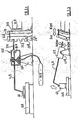
- the heater may comprise a solid state body or store which incorporates a system of passageways extending upwardly from inlets to outlets, the latter being controlled by air flow control means comprising a damper or valve element in the form of a flap 10 pivoted about a horizontal axis 11 offset to one side (e.g. the rear side as illustrated) of a frame element 12 forming the outlet of the system of passageways.
- air flow control means comprising a damper or valve element in the form of a flap 10 pivoted about a horizontal axis 11 offset to one side (e.g. the rear side as illustrated) of a frame element 12 forming the outlet of the system of passageways.
- the flap 10 is biased towards its shut position and can be moved towards its open position as indicated by arrow 13 by downward pressure exerted by an arm in the form of a bi-metal strip14.
- the bi-metal strip 14 is in turn supported from a carrier in the form of a housing 15 to which it is pivoted about a horizontal axis 16 transverse to the length of the arm, the frame itself being pivoted about a horizontal transverse axis 17 to a bracket 18 or other fixed support mounted at the upper end of the heater.
- the pivotal movement of the frame 15 in a clockwise direction is limited by a stop element 19, forming part of a setting means of the heater, projecting upwardly from one end of a further bi-metal strip 20 which in turn is supported from a bracket 22 carried by any suitable fixed part of the heater in such a manner that it deflects upwardly for increase of store temperature and downwardly for decrease in store temperature.
- the bi-metal strip 20 is formed with a central medially extending slot 23 through which projects one element of a latch means comprising a strip 24, one edge of which is formed with a series of teeth 25 and intervening slots 26 which can co-operate with the other element of the latch means formed by the marginal portion 27 of the strip 20 bordering the adjacent end of the slot 23.
- the strip 24 is mounted on a fixed bracket 28 for pivotal movement about a transverse horizontal axis 29 and is connected by a link 30 to an upstanding bi-metal strip 31 of a resetting device of the heater which is secured to a fixed part of the heater and with which is associated an electrical heating element 32 connected in the charging circuit of the heater so as to be energised whenever heating current is being passed through the electrical heating means of the store from the off-peak supply.
- a capsule or bellows 33 connected by a pipe 34 to a heat sensing element 35 in the form of a phial, the phial, pipe, and bellows containing a liquid, the vapour pressure of which rises in response to rise of temperature.
- the phial 35 is sited adjacent to an inlet of the passageway system already referred to so as to partake of the temperature of the air in the space or place to be heated and which enters the heater and flows convectively through the passageway system of the store when the flap 10 is in its open position.
- Control of the charging current during the off-peak period is determined by an automatically operating charge control means responsive to the parameters of the store temperature and the temperature of the space or place to be heated (which is indirectly related to weather temperature) possibly by the means described and claimed in our co-pending British Application already referred to.
- the strip 20 is sited so as to partake of the store temperature. Thus, it may be situated adjacent to part of the insulating covering of the store but on the outside of the covering.
- a spring 36 acting between the frame 15 and a fixed part of the heater urges the frame clockwise, and maintains contact between the tail section 37 of the frame 15 and the upwardly presented edge face of the stop element 19.
- the charge control means will cause current to be cut off from the element 32 and the strips 31 and 24 will move anti-clockwise to the "day" position causing the toothed edge to interengage with the margin 27 and holding the bi-metal strip 20 and stop element 19 in the position which they then occupy and which will be a function of store temperature at the end of, or in the terminal portion of, the off-peak charging period.
- a bias is introduced to vary the manner in which the flow control means responds to the input signals, to compensate for the level of charging of the device at the end of the off-peak period.
- the bi-metal arm 14 may already be exerting downward pressure on the flap 10 at a position to the rear of axis 11 but insufficient pressure to cause the flap to open against its own weight.
- the position of a stop element 19 will then determine the magnitude of such pressure, and the term "setting" as herein used is to be deemed to refer either to the gap or to the pressure as appropriate.
- the primary factors determining the point at which the flap 10 opens will be the temperature to which the bi-metal strip 14 is subjected and the temperature to which the phial 35 is subjected as more fully described in our European Application already mentioned.
- a higher temprature in respect of the store causes the bi-metal strip 14 to bend upwardly and a higher temperature in respect of the phial 35 causes the strip 14 to pivot relatively to the frame 15 about an axis 16 to a limit determined by the position of the stop element 40 which may be in the form of an adjustable screw as shown.
- the bi-metal strip 20 will have bent towards a lower position and will have become latched in that position and so opening of the flap 10 in the succeeding on-peak peiod will be delayed.
- the bi-metal strip 20 will have bent upwardly raising the stop element 19 to decrease the gap or increase the downard pressure existing between the strip 14 and the flap 10.
- All the operating elements of the device are thermo-motive and derive their energy from the air in the space or place to be heated or from the store and therefore do not require to draw any current from the on-peak supply.
- the resetting bi-metal element 31 On commencement of the next subsequent off-peak period, the resetting bi-metal element 31 will be heated by the heating element 32 (located in the charging circuit), causing the bi-metal 31 to move to its "night" position, disengaging the toothed formation frm the bi-metal strip 20. In consequence, the bi-metal strip 20 will be free to move to a possibly different position during recharging of the heater, in the terminal position of which it will be re-engaged by the latch at the end of that off-peak period.
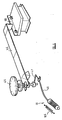
- the heater which is the second embodiment of this invention is generally similar to the first embodiment above described, and similar numerals with the suffix a have been used to indicate elements of the heater similar to those described in detail in the first embodiment.
- the housing 15 a is pivotally mounted on a bracket 18 a , the actuating bi-metal arm 14 a being pivotally mounted on the housing at 16 a .
- Extending rearwardly from the housing is a tail section 37 a .
- a bi-metal setting element 40 is interposed between the actuating arm 14 a and the flap 10 a of the damper.
- a latch element 24 a mounted behind the tail section 37 a is a latch element 24 a , provided with teeth 25 a , secured by a link 30 to a bi-metal lock release mechanism 31 a , affording the resetting means of the heater.
- the bi-metal strip 31 a is adapted to be heated by a heating element 32 a during charging of the heater, the "day" position being shown in Figure 2 a , and the "night” position being shown in Figure 2 b .
- the latch element 24 a adopts a position in which the housing 15 a is free to pivot on about its horizontal axis 17 a .
- the bi-metal setting element 40 is located at a position in which it responds to the temperature of the heat store, and will "elevate” (as is shown in Figure 2 b ) to push the housing 15 a in a clockwise direction in accordance with the level of charging of the heat store.
- the bi-metal strip 31 a will move the left, causing the latch element 24 a to pivot about its axis 29 a in an anti-clockwise direction. Moving the teeth 25 a into engagement with the tail section 37 a , retaining the housing 15 a in the angular position about axis 17 a .
- the bi-metal element 31 a upon commencement of the next off-peak charging period, the bi-metal element 31 a will flex to the right, pulling the latch element 24 a from engagement with the tail section 37 a , preventing opening of the flap 10 a and permitting the housing 15 a to find a new angular position determined by the level of charging which takes place, for subsequent re-latching at the end of that charging period.
- the heaters described and illustrated above are similar in that both are provided with means automatically to bias the flow control means, in accordance with the level to which the heater is charged during each off-peak period.
- the heater which is the third embodiment of this invention is such a heater, being in other respects similar to the heater described in relation to Figure 1, and in relation of which the same numerals with the suffix b have been used to indicate similar parts.
- the flow control means comprises a housing 15 b mounted on a pivot 17 b , and urged by a spring 36 b in a clockwise direction.
- a bi-metal control arm 14 b On the housing for movement about a pivot axis 16 b , is a bi-metal control arm 14 b , an end portion of the arm being provided with a tip 39 b adapted to engage a flap (not shown) of a damper of the heater.
- downward movement of the tip 39 b produces pivotal movement of the flap, causing opening of the damper and release of heated air.
- the position of the control arm 14 b is determined by a rotary control knob 42, a stem portion of which presses against the arm 14 b to urge it in an anti-clockwise direction, whilst to the left thereof a bellows 33 b acts against the arm to urge it abouts its pivotal axis 16 b in a clockwise direction, under the action of expanding fluid in a heat sensing file 35 b .
- a bi-metal latch element 24 b Adjacent to a tail section 37 b of the housing 15 b is a bi-metal latch element 24 b , adjacent to which a heating element 32 b extends, the heating element 32 b being in the charging circuit of the heater, and being adapted to be heated during the off-peak charging period.
- the latch element 24 b is shown in Figure 3 in its rest position during an on-peak period, in which its natural resilience urges it into contact with the tail section 37 b .
- the flow control means of the third embodiment comprises a "heat boost" means, which may be provided by the control knob 42 or an additional control knob, by which the housing 15 b may be urged as a whole in an anti-clockwise direction about its pivotal axis 17 b , into engagement with a stop 43. Such movement causes the actuator tip 39 b to move the flap into a more open position, to increase the rate at which heat flows from the heater.
- the latch element 24 b passes beneath the tail section 37 b retaining the housing in a position in which the delivery of heat is boosted as has been described.
- the heating element 32 b causes heating of the bimetal match element 24 b , causing movement thereof to the right, from beneath the tail section 37 b , permitting the spring 36 b to pull the housing to its "unboosted" position, conveniently defined by a further stop (not shown) against which the housing is pulled in a clockwise direction by the spring 36 b .
- the bias provided by operation if the "boost" control is removed prior to commencement of the next on-peak period, and ensures that an unduly high release of heat from the heater is not inadvertently produced by failure to release the boost control manually.
- the heater which is the fourth embodiment of this invention is illustrated in Figure 4, in which similar numerials with the suffix c have been used to denote light parts, is also similar to the first embodiment described above and illustrated in Figure 1.
- the setting means is afforded solely by a manually operable control knob 42 c , which is used to determined the base position of the control arm 14 c .
- the control knob is movable from a "minimum"position corresponding the normal temperature sat which it is desired to maintain the room being served, and may be used (particularly during the latter part of an on-peak period) to a higher setting to increase the rate of delivery of heat.
- a resetting device 45 is used, which is adapted to be heated by as heating element 32 c which is in a charging circuit of the heater.
- the resetting device 45 is of the type referred to as a "magic spring", which produces a significant degree of movement in response to small specific temperature changes.
- the "magic spring” element is connected to a bowden cable 46, the inner member of which is connected to an arm 47 attached to the control knob 42 c . In this manner on commencement of an off-peak charging period, heating of the resetting device occurs causing the bowden cable 46 to contract, moving the arm 47 in a clockwise direction to return the user control knob 42 c to its rest position.
Landscapes
- Engineering & Computer Science (AREA)
- Physics & Mathematics (AREA)
- General Physics & Mathematics (AREA)
- Automation & Control Theory (AREA)
- Thermal Sciences (AREA)
- Chemical & Material Sciences (AREA)
- Combustion & Propulsion (AREA)
- Mechanical Engineering (AREA)
- General Engineering & Computer Science (AREA)
- Control Of Resistance Heating (AREA)
- Central Heating Systems (AREA)
- Control Of Temperature (AREA)
Applications Claiming Priority (2)
| Application Number | Priority Date | Filing Date | Title |
|---|---|---|---|
| GB8718965 | 1987-08-11 | ||
| GB8718965A GB2207994B (en) | 1987-08-11 | 1987-08-11 | Improvements relating to electrical storage heaters |
Publications (2)
| Publication Number | Publication Date |
|---|---|
| EP0303395A2 true EP0303395A2 (de) | 1989-02-15 |
| EP0303395A3 EP0303395A3 (de) | 1990-07-11 |
Family
ID=10622119
Family Applications (1)
| Application Number | Title | Priority Date | Filing Date |
|---|---|---|---|
| EP88307176A Withdrawn EP0303395A3 (de) | 1987-08-11 | 1988-08-03 | Elektrische Speicheröfen |
Country Status (5)
| Country | Link |
|---|---|
| US (1) | US4894516A (de) |
| EP (1) | EP0303395A3 (de) |
| JP (1) | JPH01139956A (de) |
| GB (1) | GB2207994B (de) |
| NZ (1) | NZ225731A (de) |
Families Citing this family (4)
| Publication number | Priority date | Publication date | Assignee | Title |
|---|---|---|---|---|
| GB2242974B (en) * | 1990-04-10 | 1994-02-09 | Creda Ltd | Electrical storage heater |
| GB2283809B (en) * | 1993-11-12 | 1997-07-23 | Creda Ltd | Electrical storage heaters |
| US5809941A (en) * | 1996-04-16 | 1998-09-22 | Allaire; Ernest Lee | High efficiency hot water heater for recreational vehicles |
| US7282148B2 (en) * | 2003-10-30 | 2007-10-16 | International Business Machines Corporation | Porous silicon composite structure as large filtration array |
Family Cites Families (8)
| Publication number | Priority date | Publication date | Assignee | Title |
|---|---|---|---|---|
| GB891040A (en) * | 1959-06-08 | 1962-03-07 | Gen Electric Co Ltd | Improvements in or relating to electric thermal storage space heaters |
| FR1488816A (fr) * | 1963-10-28 | 1967-07-13 | Witte Haustechnik Gmbh | Appareil de commande de charge pour accumulateurs de chaleur électriques |
| DE1615409A1 (de) * | 1967-09-15 | 1970-06-18 | Siemens Elektrogeraete Gmbh | Elektrischer Waermespeicherofen |
| GB1190323A (en) * | 1968-02-12 | 1970-05-06 | Potterton Internat Ltd | Control means for Electrical Storage Heaters |
| DE2433517A1 (de) * | 1974-07-12 | 1976-01-22 | Licentia Gmbh | Steueranordnung fuer einen waermespeicherofen |
| DE2539065C3 (de) * | 1975-09-03 | 1978-05-11 | Danfoss A/S, Nordborg (Daenemark) | Aufladeeinrichtung fur eine elektrische Speicherheizung |
| US4473740A (en) * | 1979-04-03 | 1984-09-25 | Ti Creda Manufacturing Limited | Dual temperature responsive control for air outlet of electric heater with heat storage capacity |
| GB2097912B (en) * | 1981-03-10 | 1985-05-01 | Ti Creda Manufacturing Ltd | Electrical storage heaters |
-
1987
- 1987-08-11 GB GB8718965A patent/GB2207994B/en not_active Expired - Lifetime
-
1988
- 1988-08-03 EP EP88307176A patent/EP0303395A3/de not_active Withdrawn
- 1988-08-08 NZ NZ225731A patent/NZ225731A/en unknown
- 1988-08-11 US US07/231,033 patent/US4894516A/en not_active Expired - Fee Related
- 1988-08-11 JP JP63201011A patent/JPH01139956A/ja active Pending
Also Published As
| Publication number | Publication date |
|---|---|
| GB2207994A (en) | 1989-02-15 |
| EP0303395A3 (de) | 1990-07-11 |
| GB2207994B (en) | 1990-12-12 |
| GB8718965D0 (en) | 1987-09-16 |
| US4894516A (en) | 1990-01-16 |
| NZ225731A (en) | 1990-01-29 |
| JPH01139956A (ja) | 1989-06-01 |
Similar Documents
| Publication | Publication Date | Title |
|---|---|---|
| US4340355A (en) | Furnace control using induced draft blower, exhaust gas flow rate sensing and density compensation | |
| US4894516A (en) | Electrical storage heaters | |
| EP0017476B1 (de) | Verbesserungen an elektrischen Speicheröfen | |
| US2558610A (en) | Control device | |
| US3997107A (en) | Servo modulating regulating control system | |
| US2238219A (en) | Temperature controlling device | |
| US3859616A (en) | Temperature control device | |
| US2181427A (en) | Temperature control system | |
| US2297706A (en) | Temperature controller | |
| GB1351009A (en) | Controlling electric thermal storage heaters | |
| US2640649A (en) | Thermostatic control apparatus for heating systems | |
| US2932456A (en) | Temperature control system and compensated thermostat therefor | |
| US1901070A (en) | Motor operated valve | |
| US2733315A (en) | Cold wall thermostat | |
| US2235210A (en) | Self-compensating thermostatic apparatus | |
| US1794530A (en) | Furnace-control apparatus | |
| US4014499A (en) | Temperature control apparatus | |
| US2250439A (en) | Stack switch | |
| NZ534056A (en) | Storage heaters | |
| US2672291A (en) | Furnace control means | |
| US2345981A (en) | Condition control means | |
| GB2097912A (en) | Electrical storage heaters | |
| US5280559A (en) | Electrical storage heater | |
| US2631598A (en) | Automatically operated valve | |
| US2933256A (en) | Anticipated mechanical thermostat |
Legal Events
| Date | Code | Title | Description |
|---|---|---|---|
| PUAI | Public reference made under article 153(3) epc to a published international application that has entered the european phase |
Free format text: ORIGINAL CODE: 0009012 |
|
| AK | Designated contracting states |
Kind code of ref document: A2 Designated state(s): AT BE CH DE ES FR GR IT LI LU NL SE |
|
| PUAL | Search report despatched |
Free format text: ORIGINAL CODE: 0009013 |
|
| AK | Designated contracting states |
Kind code of ref document: A3 Designated state(s): AT BE CH DE ES FR GR IT LI LU NL SE |
|
| 17P | Request for examination filed |
Effective date: 19900622 |
|
| STAA | Information on the status of an ep patent application or granted ep patent |
Free format text: STATUS: THE APPLICATION HAS BEEN WITHDRAWN |
|
| 18W | Application withdrawn |
Withdrawal date: 19900910 |
|
| R18W | Application withdrawn (corrected) |
Effective date: 19900910 |