EP0303394A2 - System zur Steuerung der elektrischen Stromversorgung während der Niedertarifzeit - Google Patents
System zur Steuerung der elektrischen Stromversorgung während der Niedertarifzeit Download PDFInfo
- Publication number
- EP0303394A2 EP0303394A2 EP88307175A EP88307175A EP0303394A2 EP 0303394 A2 EP0303394 A2 EP 0303394A2 EP 88307175 A EP88307175 A EP 88307175A EP 88307175 A EP88307175 A EP 88307175A EP 0303394 A2 EP0303394 A2 EP 0303394A2
- Authority
- EP
- European Patent Office
- Prior art keywords
- peak
- current
- period
- battery
- controlling
- Prior art date
- Legal status (The legal status is an assumption and is not a legal conclusion. Google has not performed a legal analysis and makes no representation as to the accuracy of the status listed.)
- Withdrawn
Links
Images

Classifications
-
- F—MECHANICAL ENGINEERING; LIGHTING; HEATING; WEAPONS; BLASTING
- F24—HEATING; RANGES; VENTILATING
- F24H—FLUID HEATERS, e.g. WATER OR AIR HEATERS, HAVING HEAT-GENERATING MEANS, e.g. HEAT PUMPS, IN GENERAL
- F24H9/00—Details
- F24H9/20—Arrangement or mounting of control or safety devices
- F24H9/2064—Arrangement or mounting of control or safety devices for air heaters
- F24H9/2071—Arrangement or mounting of control or safety devices for air heaters using electrical energy supply
- F24H9/2078—Storage heaters
-
- G—PHYSICS
- G05—CONTROLLING; REGULATING
- G05D—SYSTEMS FOR CONTROLLING OR REGULATING NON-ELECTRIC VARIABLES
- G05D23/00—Control of temperature
- G05D23/19—Control of temperature characterised by the use of electric means
- G05D23/1919—Control of temperature characterised by the use of electric means characterised by the type of controller
- G05D23/1923—Control of temperature characterised by the use of electric means characterised by the type of controller using thermal energy, the cost of which varies in function of time
Definitions
- This invention concerns the control of the supply of current to an electrically energised apparatus which is required normally to be energised only during certain periods (herein called off-peak periods) during a basic period, normally 24 hours, and maintained in a non- energised state during the remaining periods (herein called the on-peak periods).
- the form of apparatus for which this requirement most often applies is an electrical storage heater comprising a heat store, electrical heating means for heating said store, means providing for flow of air or other heat distributing fluid (herein for convenience referred to as air) into contact with the heat store and thereafter to a space or place to be heated.
- air heat distributing fluid
- Preferably flow control means are provided for controlling the flow of such air.
- the normal practice in premises in which electrical storage heaters are installed is for the supply of current to be taken from a main programming means which comprises a main switch, a main timing means, for operating the switch, metering means having metering units for separate registration in terms of energy consumed respectively over off-peak periods and on-peak periods, and output terminal means.
- a main programming means which comprises a main switch, a main timing means, for operating the switch, metering means having metering units for separate registration in terms of energy consumed respectively over off-peak periods and on-peak periods, and output terminal means.
- One of the most common arrangements is for the main programming means to include a first set of output terminals (herein called all services terminals) connected to conductors which constitute the wiring of the premises and which feed any electrically energised apparatus which may be in use, and a separate set of terminals (herein called the off-peak terminals) which are connected to a separate set of conductors which constitute another part of the wiring of the premises and which feed only the heat storage heaters.
- all services terminals connected to conductors which constitute the wiring of the premises and which feed any electrically energised apparatus which may be in use
- the off-peak terminals separate set of terminals
- the electrical storage heater may be connected to the conductors which are connected to the all services terminals, and the heating means which provides charging of the heat store concerned is prevented from being brought into use except during off-peak periods by a relay on the heat storage heater itself, such relay being operated by current supplied by the conductors connected to the off-peak terminals.
- Both of these arrangements entails the provision of two separate wiring systems, one being connected to the all services terminals and the other the off-peak terminals.
- the latter carries the main charging current to the heating means of the heat storage heater concerned and in the second case it carries only a control current for operating the relay.
- This requirement for a dual wiring system is an obstacle to the more extensive use of storage heaters, or for that matter electrical apparatus in general, which might advantageously be brought into use during off-peak periods.
- a main programming means which includes switch means, timing means,
- the battery powered timing means provides for establishment of said current conduction during off-peak periods each starting at a predetermined real time (time of day) and means are provided for maintaining the real time value when battery replacement is required without having to reset the timing means.
- the timing means may include means for automatically resetting it to a further predetermined real time (herein called battery changing time) whenever the battery in use is removed. The user would then be instructed to replace the battery only at the battery changing time.
- battery changing time a further predetermined real time
- An indicator such as a neon lamp, may be provided connected with the timing means in a circuit responsive to decline in the battery output (voltage or current) to signal to the user when battery changing is required.
- the indicator means may be connected to perform the dual function of indicating energisation of the output terminals during an off-peak period and, during an on-peak period, the need to effect battery replacement.
- a further rechargeable battery may be provided to keep the timing means operative to maintain real time output during changing of the battery already referred to (which need not be rechargeable), the circuit providing for recharge of the further battery from either the input or the output terminals.
- the main programming means ordinarily include a synchronous electric motor acting as the timing means and operating the switch means.
- the timing means normally includes a reserve or back-up clockwork mechanism which is able to maintain operation of the switch means in accordance with the desired off-peak on-peak programme over a period which typically may be as long as 36 hours.
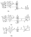
- the live line 10 is connected to a main programming means comprising a main switch 11.
- This has contacts a , b connected to respective meter units 12 and 13 of a metering means 14 selectively to bring these into operation during on-peak and off-peak periods, the output terminal 15 of the metering means being connected to contact d of the main switch 11.
- the main programming means includes two sets of output terminals 16 and 17 connected respectively to terminal 15 and to output terminal e of the main switch.
- Movable contacts of the main switch 11 are mechanically coupled as indicated at 18. When it is in its upper position during on-peak periods meter 12 is in use and all services terminal bank 16 is energised while off-peak terminal bank 17 is de-energised
- Apparatus such as an electric storage heater which is required to be energised only during off-peak periods is connected to an appropriate terminal of the terminal bank 17.
- the heating element 20 is connected to the terminal bank 17 by conductor 21 which carries the main energising current for the heating element.
- main switch 11 is operated by a timing means such as a synchronous electric motor with clockwork reserve or back-up mechanism as already mentioned.
- Figure 2 shows a modified arrangement in which parts corresponding to those already described are designated by like references.
- the storage heater 19 is connected to the all services terminal bank 16 and the main conductor 22 serves to convey the main energising current, in this case through contacts f , g of a relay 23 connected by conductor 24 to off-peak terminal bank 17.
- conductor 24 conveys only controlling or pilot current by effecting some economy in the installation.
- the storage heater 19 it is not possible in either system for the storage heater 19 to have its heat store charged by energisation of the heating element 20 during on-peak periods unless a manually operable change-over switch were provided, in the case of the arrangement of Figure 1 selectively to connect the heater 19 directly to the all services terminal bank or an appropriate connection point in the existing wiring connected thereto, and in the case of Figure 2 to short circuit contacts f , g of the relay. avoids the relatively expensive necessity of the additional wiring connected to the off-peak terminal banks 17. Further,
- the secondary programming means comprises input terminals t1 which would be connected to the conductor 122 and t2 which would be connected to the neutral line of the supply. Further, it comprises output terminals t3 connected to the heating element 120 and t4 which is the neutral terminal.
- a relay contact 126 maintained open during on-peak periods and closed during off-peak periods is controlled by a timing means which comprises a battery energised electronic timer 125 providing an ouput on line 133 at a predetermined real time, e.g. 2400 hours, to a circuit 127 controlling energisation of the relay card for operating contacts 126, the contacts of 126 remaining closed during off-peak periods.
- a timing means which comprises a battery energised electronic timer 125 providing an ouput on line 133 at a predetermined real time, e.g. 2400 hours, to a circuit 127 controlling energisation of the relay card for operating contacts 126, the contacts of 126 remaining closed during off-peak periods.
- the battery 128 which may be of the pen-torch type serves as the power source.
- the programmer may be provided with means for setting it automatically to a predetermined real time (say 2400 hours) wherein the battery 128 is removed for replacement.
- the programmer would have affixed to it an instruction to replace the battery only at this time.
- a secondary cell or rechargeable battery 128 a may be connected in parallel with battery 128 to keep the programmer operating to provide true real time output on line 133 during battery charging.
- the rechargeable battery may be connected to a charging circuit 129 energised from neutral line and terminal t3.
- the secondary programming means is preferably provided with an indicator means 132 such as a glow lamp which would be energised during off-peak periods in the connection between the neutral line and terminal t3 or other appropriate connection.
- an indicator means 132 such as a glow lamp which would be energised during off-peak periods in the connection between the neutral line and terminal t3 or other appropriate connection.
- the secondary programming means may of course be used with other forms of electrical apparatus which may be required to be brought into operation during off-peak periods, for example air conditioning apparatus, security apparatus and so forth.
Landscapes
- Engineering & Computer Science (AREA)
- Physics & Mathematics (AREA)
- Thermal Sciences (AREA)
- Chemical & Material Sciences (AREA)
- Combustion & Propulsion (AREA)
- Mechanical Engineering (AREA)
- General Engineering & Computer Science (AREA)
- General Physics & Mathematics (AREA)
- Automation & Control Theory (AREA)
- Charge And Discharge Circuits For Batteries Or The Like (AREA)
- Measurement Of Current Or Voltage (AREA)
- Measuring Volume Flow (AREA)
Applications Claiming Priority (2)
| Application Number | Priority Date | Filing Date | Title |
|---|---|---|---|
| GB8718963 | 1987-08-11 | ||
| GB08718963A GB2208050A (en) | 1987-08-11 | 1987-08-11 | Controlling supply of electric current during off-peak supply periods |
Publications (2)
| Publication Number | Publication Date |
|---|---|
| EP0303394A2 true EP0303394A2 (de) | 1989-02-15 |
| EP0303394A3 EP0303394A3 (de) | 1990-05-30 |
Family
ID=10622118
Family Applications (1)
| Application Number | Title | Priority Date | Filing Date |
|---|---|---|---|
| EP88307175A Withdrawn EP0303394A3 (de) | 1987-08-11 | 1988-08-03 | System zur Steuerung der elektrischen Stromversorgung während der Niedertarifzeit |
Country Status (2)
| Country | Link |
|---|---|
| EP (1) | EP0303394A3 (de) |
| GB (1) | GB2208050A (de) |
Family Cites Families (9)
| Publication number | Priority date | Publication date | Assignee | Title |
|---|---|---|---|---|
| GB1396867A (en) * | 1971-10-01 | 1975-06-11 | Gkn Building Supplies Services | Heating systems |
| US3958101A (en) * | 1973-03-08 | 1976-05-18 | Saskatchewan Power Corporation | Space heating using off-peak electric heat storage |
| GB1491314A (en) * | 1976-04-23 | 1977-11-09 | London Electricity Board Sheph | Control of electrical apparatus utilising power during preferred periods |
| FR2353195A1 (fr) * | 1976-05-24 | 1977-12-23 | Duquesne Maurice | Dispositif de regulation de chauffage electrique par accumulation en fonction de la temperature exterieure |
| US4234782A (en) * | 1978-01-19 | 1980-11-18 | Saskatchewan Power Corporation | Space heating using off-peak electric heat storage |
| GB2050717A (en) * | 1979-05-17 | 1981-01-07 | Horstmann Gear Group Ltd | Switching circuit controlled by a clock |
| GB2130449A (en) * | 1982-11-16 | 1984-05-31 | Schlumberger Electronics | Time switches |
| FR2552210B1 (fr) * | 1983-09-21 | 1989-05-19 | Chauffe Eau Cie Indle | Procede et dispositif de decalage de l'enclenchement d'une puissance de chauffe dans un chauffe-eau |
| GB2179215A (en) * | 1985-08-09 | 1987-02-25 | Frederick Greenwood & Sons Ltd | Electrical appliances for low tariff electricity |
-
1987
- 1987-08-11 GB GB08718963A patent/GB2208050A/en not_active Withdrawn
-
1988
- 1988-08-03 EP EP88307175A patent/EP0303394A3/de not_active Withdrawn
Also Published As
| Publication number | Publication date |
|---|---|
| GB8718963D0 (en) | 1987-09-16 |
| GB2208050A (en) | 1989-02-15 |
| EP0303394A3 (de) | 1990-05-30 |
Similar Documents
| Publication | Publication Date | Title |
|---|---|---|
| US4447712A (en) | Heating system | |
| EP0241526B1 (de) | Regel- und schaltvorrichtung für elektrische heizung | |
| US4027171A (en) | Power demand limiting system | |
| US20090045676A1 (en) | Controlling Power Supply to Vehicles Through a Series of Electrical Outlets | |
| US9738165B2 (en) | Controlling power supply to vehicles through a series of electrical outlets | |
| US4317987A (en) | Remote control device for a water heater | |
| US3646356A (en) | Control system for starting up and synchronizing a plurality of generators and method of operation | |
| WO1994007090A1 (en) | Back up power source for a thermostat | |
| US4737615A (en) | Energy saving control circuit for hot water heater | |
| EP0303394A2 (de) | System zur Steuerung der elektrischen Stromversorgung während der Niedertarifzeit | |
| US3261992A (en) | Electrical load balancing control system | |
| US1704996A (en) | Automatic generating plant | |
| US1710542A (en) | Emergency lighting system | |
| US3108190A (en) | Plural battery system for vehicles | |
| CA2598012C (en) | Controlling power supply to vehicles through a series of electrical outlets | |
| CN121399815A (zh) | 能量存储和分配系统 | |
| JP6675091B2 (ja) | 切換盤、配電システム、コントローラ | |
| CN115811039A (zh) | 一种功率分配控制电路、充电桩控制器及充电桩 | |
| US4843251A (en) | Energy storage and supply system | |
| US2804554A (en) | Emergency stand-by electric service apparatus | |
| SU681501A1 (ru) | Автономна система электроснабжени передвижных объектов | |
| US8849470B2 (en) | Method for performing service/maintenance on a switchgear panel, and related switchgear panel | |
| GB2050717A (en) | Switching circuit controlled by a clock | |
| WO1993020577A1 (en) | A device for controlling the switching-on and switching-off of consumer groups in existing current distribution boards | |
| CN218569836U (zh) | 一种双路电源冗余供电装置 |
Legal Events
| Date | Code | Title | Description |
|---|---|---|---|
| PUAI | Public reference made under article 153(3) epc to a published international application that has entered the european phase |
Free format text: ORIGINAL CODE: 0009012 |
|
| AK | Designated contracting states |
Kind code of ref document: A2 Designated state(s): AT BE CH DE ES FR GR IT LI LU NL SE |
|
| PUAL | Search report despatched |
Free format text: ORIGINAL CODE: 0009013 |
|
| AK | Designated contracting states |
Kind code of ref document: A3 Designated state(s): AT BE CH DE ES FR GR IT LI LU NL SE |
|
| RHK1 | Main classification (correction) |
Ipc: G05D 23/19 |
|
| STAA | Information on the status of an ep patent application or granted ep patent |
Free format text: STATUS: THE APPLICATION IS DEEMED TO BE WITHDRAWN |
|
| 18D | Application deemed to be withdrawn |
Effective date: 19901201 |