EP0303219A2 - Verfahren zur Herstellung eines dauerhaft formstabilen und elastischen Gegenstandes - Google Patents
Verfahren zur Herstellung eines dauerhaft formstabilen und elastischen Gegenstandes Download PDFInfo
- Publication number
- EP0303219A2 EP0303219A2 EP88112892A EP88112892A EP0303219A2 EP 0303219 A2 EP0303219 A2 EP 0303219A2 EP 88112892 A EP88112892 A EP 88112892A EP 88112892 A EP88112892 A EP 88112892A EP 0303219 A2 EP0303219 A2 EP 0303219A2
- Authority
- EP
- European Patent Office
- Prior art keywords
- mat
- compartments
- pressure
- liquid
- rubber
- Prior art date
- Legal status (The legal status is an assumption and is not a legal conclusion. Google has not performed a legal analysis and makes no representation as to the accuracy of the status listed.)
- Granted
Links
- 230000003068 static effect Effects 0.000 title claims abstract description 29
- 238000000034 method Methods 0.000 title claims abstract description 10
- 230000008569 process Effects 0.000 title claims abstract description 10
- 239000007788 liquid Substances 0.000 claims abstract description 59
- 229920001971 elastomer Polymers 0.000 claims abstract description 38
- 238000010438 heat treatment Methods 0.000 claims abstract description 23
- 239000000806 elastomer Substances 0.000 claims abstract description 19
- 239000005060 rubber Substances 0.000 claims description 19
- 239000013536 elastomeric material Substances 0.000 claims description 11
- PEDCQBHIVMGVHV-UHFFFAOYSA-N Glycerine Chemical compound OCC(O)CO PEDCQBHIVMGVHV-UHFFFAOYSA-N 0.000 claims description 6
- 229920000459 Nitrile rubber Polymers 0.000 claims description 3
- 229920002943 EPDM rubber Polymers 0.000 claims description 2
- 244000043261 Hevea brasiliensis Species 0.000 claims description 2
- 239000000203 mixture Substances 0.000 claims description 2
- 229920003052 natural elastomer Polymers 0.000 claims description 2
- 229920001194 natural rubber Polymers 0.000 claims description 2
- 229920001084 poly(chloroprene) Polymers 0.000 claims description 2
- 229920003048 styrene butadiene rubber Polymers 0.000 claims description 2
- XLYOFNOQVPJJNP-UHFFFAOYSA-N water Substances O XLYOFNOQVPJJNP-UHFFFAOYSA-N 0.000 claims description 2
- RRHGJUQNOFWUDK-UHFFFAOYSA-N Isoprene Chemical compound CC(=C)C=C RRHGJUQNOFWUDK-UHFFFAOYSA-N 0.000 claims 2
- 210000002421 cell wall Anatomy 0.000 claims 1
- 239000002562 thickening agent Substances 0.000 claims 1
- 239000000463 material Substances 0.000 abstract description 14
- 230000008859 change Effects 0.000 description 13
- 210000002414 leg Anatomy 0.000 description 8
- 238000012360 testing method Methods 0.000 description 8
- 210000003205 muscle Anatomy 0.000 description 7
- 230000006835 compression Effects 0.000 description 6
- 238000007906 compression Methods 0.000 description 6
- 230000000694 effects Effects 0.000 description 6
- 230000000873 masking effect Effects 0.000 description 6
- 210000002683 foot Anatomy 0.000 description 5
- 230000007423 decrease Effects 0.000 description 4
- 238000005259 measurement Methods 0.000 description 4
- 230000003867 tiredness Effects 0.000 description 4
- 208000016255 tiredness Diseases 0.000 description 4
- 238000012937 correction Methods 0.000 description 3
- 238000002347 injection Methods 0.000 description 3
- 239000007924 injection Substances 0.000 description 3
- 230000007774 longterm Effects 0.000 description 3
- 230000011514 reflex Effects 0.000 description 3
- 230000035939 shock Effects 0.000 description 3
- 238000004073 vulcanization Methods 0.000 description 3
- 230000004913 activation Effects 0.000 description 2
- 238000000418 atomic force spectrum Methods 0.000 description 2
- 230000017531 blood circulation Effects 0.000 description 2
- 230000003247 decreasing effect Effects 0.000 description 2
- 238000011835 investigation Methods 0.000 description 2
- 238000004519 manufacturing process Methods 0.000 description 2
- 238000005086 pumping Methods 0.000 description 2
- 230000009467 reduction Effects 0.000 description 2
- 230000002829 reductive effect Effects 0.000 description 2
- 230000002441 reversible effect Effects 0.000 description 2
- 238000000926 separation method Methods 0.000 description 2
- 230000008961 swelling Effects 0.000 description 2
- 229920002134 Carboxymethyl cellulose Polymers 0.000 description 1
- 239000006096 absorbing agent Substances 0.000 description 1
- 230000015572 biosynthetic process Effects 0.000 description 1
- 238000009835 boiling Methods 0.000 description 1
- 238000003490 calendering Methods 0.000 description 1
- 239000001768 carboxy methyl cellulose Substances 0.000 description 1
- 235000010948 carboxy methyl cellulose Nutrition 0.000 description 1
- 239000008112 carboxymethyl-cellulose Substances 0.000 description 1
- 229940105329 carboxymethylcellulose Drugs 0.000 description 1
- 238000013329 compounding Methods 0.000 description 1
- 230000001143 conditioned effect Effects 0.000 description 1
- 238000001816 cooling Methods 0.000 description 1
- 230000032798 delamination Effects 0.000 description 1
- 238000009826 distribution Methods 0.000 description 1
- 239000013013 elastic material Substances 0.000 description 1
- 238000005265 energy consumption Methods 0.000 description 1
- 239000004744 fabric Substances 0.000 description 1
- 239000000945 filler Substances 0.000 description 1
- 210000003108 foot joint Anatomy 0.000 description 1
- 210000004744 fore-foot Anatomy 0.000 description 1
- 239000003779 heat-resistant material Substances 0.000 description 1
- 210000004394 hip joint Anatomy 0.000 description 1
- 229920003049 isoprene rubber Polymers 0.000 description 1
- 210000000629 knee joint Anatomy 0.000 description 1
- 238000003475 lamination Methods 0.000 description 1
- 239000010410 layer Substances 0.000 description 1
- 239000004033 plastic Substances 0.000 description 1
- 229920003023 plastic Polymers 0.000 description 1
- 229920000728 polyester Polymers 0.000 description 1
- 238000004080 punching Methods 0.000 description 1
- 230000000284 resting effect Effects 0.000 description 1
- 239000011359 shock absorbing material Substances 0.000 description 1
- 239000002356 single layer Substances 0.000 description 1
- 230000006641 stabilisation Effects 0.000 description 1
- 230000036962 time dependent Effects 0.000 description 1
- 238000009834 vaporization Methods 0.000 description 1
- 230000008016 vaporization Effects 0.000 description 1
- 239000002966 varnish Substances 0.000 description 1
- 210000003462 vein Anatomy 0.000 description 1
- 239000004636 vulcanized rubber Substances 0.000 description 1
Images
Classifications
-
- A—HUMAN NECESSITIES
- A61—MEDICAL OR VETERINARY SCIENCE; HYGIENE
- A61H—PHYSICAL THERAPY APPARATUS, e.g. DEVICES FOR LOCATING OR STIMULATING REFLEX POINTS IN THE BODY; ARTIFICIAL RESPIRATION; MASSAGE; BATHING DEVICES FOR SPECIAL THERAPEUTIC OR HYGIENIC PURPOSES OR SPECIFIC PARTS OF THE BODY
- A61H39/00—Devices for locating or stimulating specific reflex points of the body for physical therapy, e.g. acupuncture
- A61H39/04—Devices for pressing such points, e.g. Shiatsu or Acupressure
-
- A—HUMAN NECESSITIES
- A47—FURNITURE; DOMESTIC ARTICLES OR APPLIANCES; COFFEE MILLS; SPICE MILLS; SUCTION CLEANERS IN GENERAL
- A47C—CHAIRS; SOFAS; BEDS
- A47C15/00—Other seating furniture
- A47C15/004—Seating furniture for specified purposes not covered by main groups A47C1/00 or A47C9/00
-
- A—HUMAN NECESSITIES
- A47—FURNITURE; DOMESTIC ARTICLES OR APPLIANCES; COFFEE MILLS; SPICE MILLS; SUCTION CLEANERS IN GENERAL
- A47C—CHAIRS; SOFAS; BEDS
- A47C27/00—Spring, stuffed or fluid mattresses or cushions specially adapted for chairs, beds or sofas
- A47C27/08—Fluid mattresses
- A47C27/085—Fluid mattresses of liquid type, e.g. filled with water or gel
-
- A—HUMAN NECESSITIES
- A47—FURNITURE; DOMESTIC ARTICLES OR APPLIANCES; COFFEE MILLS; SPICE MILLS; SUCTION CLEANERS IN GENERAL
- A47C—CHAIRS; SOFAS; BEDS
- A47C4/00—Foldable, collapsible or dismountable chairs
- A47C4/54—Inflatable chairs
-
- A—HUMAN NECESSITIES
- A47—FURNITURE; DOMESTIC ARTICLES OR APPLIANCES; COFFEE MILLS; SPICE MILLS; SUCTION CLEANERS IN GENERAL
- A47C—CHAIRS; SOFAS; BEDS
- A47C9/00—Stools for specified purposes
Definitions
- This invention relates to a mat for supporting a person in an upright position comprising a number of adjacent interconnected liquid-filled compartments said compartments being dome shaped on at least one side of the mat and the dome-shaped compartment walls being mainly made from an elastomeric material.
- Mats of the type described above have become popular for use in places of work where one stands up during work, e.g. persons tending machines and shop personnel, because said mats have proved to prevent tiredness in and swelling of the legs.
- the pressure indicated herein are all pressures above atmospheric pressure.
- the change in the elastomeric material causing the prior art mats to slacken is presumably due to the fact that the tensile stress prevailing within the elastomeric material of the mat falls drastically in the course of time.
- the elastomer is subjected to a relaxation process.
- the prior art elastomers it has been found that the material relaxes with 10-15% per time decade, i.e. the relaxation - the fall in the tensile stress expressed in percentages - during the first 24 hours is the same as during the following 10 days and nights and during the next-following 100, etc.
- the heat treatment of the liquid-filled mat i.e. comprising an elastomeric material under heavy stress (as a consequence of a relatively high liquid pressure), apparently represents an accelerated relaxation and the relaxation cycle is hereby brought into a time decade wherein the relaxation per time unit is minor.
- the load carrying capacity of the mat is a function of the liquid pressure within the compartments and the loaded area, and it is therefore to be expected a stable condition is achieved when a person stands with both legs on the mat.
- this is not the case because, as mentioned above, subsequent to the higher load a further relaxation is produced as evidenced by one's sinking down into the mat. Since the load ordinally is not the same from one leg to the other, one feel that one leg sinks lower than the other, and this generates a reflex induced correction in the attempt to change the load or to change one's position. More importantly, the same thing happens across the plane of the individual foot in case the heel or forefoot sinks.
- a mat produced as explained above has a load carrying capacity which is 20-30% higher than that of a corresponding prior art mat.
- load carrying capacity means the force needed to achieve a given reduction of the height of the dome-shaped compartments over a support.
- the mat according to the present invention exhibits a controlled instability, i.e. it works dynamically around a stable static condition. This is achieved by designing the mat so that the static tensile stress within the compartment walls, which is the result of their elongation generated by the liquid filling, is substantially lower than the tensile stress resulting from a corresponding dynamic elongation of the compartment walls and so that the pressure of the liquid-filled compartments is above 0.5 bar.
- the ratio of the former tensile stress to the latter is less than about 0.5.
- the ratio of stress to elongation is essentially equal to the module of the material and the above discovery may thus be expressed as follows:
- the compartment wall exhibits a static module substantially lower than its dynamic module.
- the static module is the module determined after very long relaxation periods when the stress in the rubber is almost exclusively due to the stretching of the rubber molecules via crosslinkages. This module is the one determining the static stress in the compartment wall and it generates and maintains the liquid pressure within the mat.
- the dynamic module is the module measured at short term loads. As mentioned, this module must be considerably higher than the static module which is achieved by rubber molecules not chemically crosslinked but only joined by temporary physical forces which contribute to support the load.
- the short term relaxation i.e. the relaxation during the first couple of decades up to 100 minutes should be relatively high, e.g. 5-20 % in order to obtain a high degree of time-dependency with respect to the supporting function of the mat and to control the degree of desired instability.
- the relaxation during the subsequent time decades must be lower and preferably within the range of from about 3 % and about 10 % because of the other utility properties.
- the elastomer properties can be controlled by suitable choice of elastomer and compounding.
- Suitable elastomers are natural rubber, nitrile rubber, EPDM rubber, styrene butadiene rubber, chloroprene rubber and isoprene rubber.
- the elastomeric material used for obtaining the controlled instability should have an elasticity module at 300% elongation within the range of from about 50 to about 110 kp/cm2.
- Elasticity modules lower than 50 kp/cm2 requires too thick compartment walls to achieve a reasonable load carrying capacity.
- Most suitable modules have been found to be an E-module of 70 +/- 20 kp/cm2 in connection with wall thicknesses within the range of from about 1.5 to about 3.5 mm. Even lower wall thicknesses can be employed in connection with a high module but this increases the risk of puncturing the mat during use.
- the ultimate tensile strength of the elastomer should be 150 kp/cm2 at a minimum, preferably within the range above 200 kp/cm2.
- the internal pressure of the mat in combination with the geometry of the individual compartment determine the static load carrying capacity of the mat.
- This capacity can be illustrated with a curve showing the relationship between the resting load and the corresponding deformation, i.e. the compression of the compartment. In the even that the curve is determined on the basis of sufficiently long load periods the result is that the static load carrying capacity is directly proportional to the product of the supporting area and the liquid pressure within the mat.
- the load carrying capacity is substantially higher for dynamic loads than for static ones. If a single compartment is suddenly loaded with a given load the compression will be relatively small at the beginning of the loading, but subsequently the compression increases. This is mainly due to an outflow of liquid from the loaded compartment.
- this compression can be given a time factor within the range of 1 ⁇ 2 to a couple of seconds.
- mats according to the present invention exhibit the novel and surprising properties that during the subsequent period the deformation continues at a slower rate and that the deformation is no longer determined by the resistance to the outflow of the liquid, but is related to the relaxation of the heat treated rubber under the new load.
- the time factor for this deformation is within the range of from 10 to many hundreds of seconds. For instance, this effect causes a person stepping onto the mat to experience that the support slowly sinks slightly - is controlled instable - and the resulting reflex induced corrections of the weight distribution will further the vein pumping.
- the invention also relates to a process of obtaining a resilient article comprising a number of adjacent interconnected liquid filled compartments having compartment walls mainly made from an elastomeric material and having a static module which is static over a long period.
- the process of the invention comprises subjecting the resilient article to a heat treatment at a temperature of above 50°C for a period sufficiently long to reduce the liquid pressure within the compartments to a value below 50 % of the initial pressure.
- the heat treatment is effected at temperatures within the range of from 50 to 100°C depending on the chosen elastomer. At temperatures higher than about 110°C undesired phenomena in the form of boiling of the liquid and delamination of the article may occur. Below about 50°C the effect of the heat treatment is insignificant. Experience has shown that temperatures within the range of from about 60 to 95°C are suitable for treatment periods of between 5 days and nights and about 5 hours. Most preferably, the heat treatment is effected at 65-85°C for 24 to 8 hours. On the one hand, such treatment provides a static module which is stable over a long period, and on the other, it produces a suitable production cadence.
- the tensile stress in the elastomer surrounding the liquid-filled interior of the article is changed. This change can be observed by measuring the pressure in the liquid and the pressure change can be used to determine the length of the heat treatment necessary to obtain the desired decrease in the static module with a given elastomer.
- an article such as a mat is filled with so much liquid that the pressure immediately after the filling is above about 2.0 bar, e.g. 2.5-3.0 bar.
- the pressure will fall to e.g. about 0,85 bar.
- the internal pressure of the mat should be below about 50% of the pressure at the time of the filling and in practice it should be within the range of 45% and 25% of the filling pressure for the mat described in the example below.
- the dynamic module of the elastomer can be measured directly by measuring the elasticity module in a tensile strength test device.
- the static module cannot be measured in the same way because it is obtained only after constant deformation over a long period. Instead, a value which is proportional to the module can be obtained measuring the liquid pressure in an article and determining the change in the liquid pressure obtained by quite small changes in the liquid volume.
- a value which is proportional to the module can be obtained measuring the liquid pressure in an article and determining the change in the liquid pressure obtained by quite small changes in the liquid volume.
- the pressure in the mats will vary with 1.3-1.7 millibar/ml liquid. After heat treatment the pressure variations caused by variations in liquid fillings have dropped to be within the range of 0.25-0.70 millibar/ml.
- millibar/ml is an indication of the elasticity module of the elastomer, and as far as the heat treated mats are concerned their static module.
- an interesting and surprising fact is that the mats have maintained a high module towards dynamic influence irrespective of the heat treatment. This can be illustrated by taking a heat treated mat and injecting slightly more liquid into it. The pressure will then be found to have been increased by for instance 1.5 millibar/ml, exactly as it was the case with the original mat.
- the ratio of the dynamic module to the static module should preferably be higher than about 2 and preferrably within the range of 2.0-6.5 and most preferably within the range of 2.5 and 5.0.
- Another characteristic property of the mat according to the present invention is that it is composed of interconnected liquid-filled compartments having elastomeric compartment walls which have been stabilised in the shape dilated by the liquid. This stability can subsequently be determined by subjecting the mat to a test wherein the pressure of the liquid prior to and after heating is measured. Test conditions are 72°C for 12 hours. The pressure in the mat after correction for evaporization of liquid, if any, must not change more than 10% at most for mats according to the present invention, preferably 5% at a maximum.
- the pressure in the mat after the heat treatment is consequently determined partly by the filling pressure partly by the pressure reduction resulting from the heat treatment.
- the utility pressure must be chosen so as to provide the necessary static load carrying capacity in combination with the geometry of the supporting compartments. It is a characteristic property of the mat that when subjected to static loads which are encountered in practice it cannot be completely compressed. The person must be carried by the liquid but at the same time the pressure must not be so high that the mat feels too hard, i.e. the deformation under load becomes too small to have any useful effect. The mat described in the example below will typically be felt to be too hard at pressures above 1.3 bar.
- the supporting area is divided into individual compartments with non-supporting (not liquid-filled) area between them the necessary utility pressure may deviate from the above-mentioned values provided that the mat is designed with another ratio of load carrying area to non-load carrying area.
- the heat treated mats may have a static load carrying capacity which is up to 30% higher than that of a corresponding non heat treated mat and having the same internal liquid pressure. No explanantion has been found to this observation but the practical consequence thereof is that a given load carrying capacity and stepping-through resistance can be obtained with a lower pressure within the mats according the present invention, viz. as low as 0.5 bar.
- the mats according to the present invention can be filled with very substantial amounts of liquid and hence with a given geometry of the base of each compartment it is possible to obtain a thicker mat without the pressure getting too high with the resulting inconveniences for the user.
- the mat consists of two elastomer sheets vulcanized together in a given pattern allowing the injection of liquid between the two sheets to cause the formation of a system of liquid-filled compartments interconnected by flow passages.
- the desired pattern could for instance be obtained by applying a varnish to one of the two sheets prior to the vulcanization, which will then prevent the two rubber sheets from being bonded together in the areas that are to form the liquid-filled compartments and flow passages between them.
- the pattern can also be achieved by placing a heat resistant sheet comprising holes obtained by punching and preventing lamination between the two non-vulcanized rubber sheets in the desired areas.
- Another possibility for achieving the desired separations is to employ a double layer of a material shich in itself will be bonded to the rubber, and wherein the separation takes place between the two single layers of the material in question.
- a material could for instance be paper.
- mats can be produced with compartments having after filling circular, oval, oblong, or angular contours.
- the compartments may be interconnected either in one large circuit for the entire mat or in two or more individual closed circuits within the same mat.
- two or more sub-systems within the same mat one may vary its properties over its surface so that, for instance, it has a harder central area supporting well at the beginning but where, on the other hand, the sinking at standstill is higher than in the surrounding softer part of the mat.
- the compartments will become largest on the side of the mat formed by the thinnest rubber sheet when the mat is filled with liquid.
- the mat it is also possible to produce the mat so that only one side consists of an elastomeric material whereas the material on the other side is non-elastic.
- the non-elastic material may for instance comprise a fabric reinforced rubber or plastic material. Such an embodiment would be particularly preferable where the mat in use is exposed to heavy wear or unilaterally heavy loads or if it is to be fixed permanently to the place of use.
- the masking pattern used consists of interconnected circles with a diameter of 12-35 mm.
- the mat is primarily used for the support of a person in an upright position. It may be designed as a mat intended to be placed on the floor in front of a working place and with the outer dimensions of the mat being adapted to the requirements for freedom of movement during work. It may be advantageous to divide a large mat into sections capable of being linked together. It will also be possible to subdivide a large mat so that the geometry or liquid pressure of the compartments vary from one section to the other. Thus it would for instance be possible to make the central area more instable to further the vene pumping whereas the remote parts are made more shock absorbant as regards walking for the purpose of fetching or delivering materials.
- the mats as support in or as part of a shoe giving particularly shock-absorbing effects in combination with control instability at standstill.
- Measurement of the load carrying capacity of the mat can be made by compressing a single compartment in a well defined way and by measuring the force which during compression acts between the compartment and the piston compressing the compartment.
- the force is substantially above the static load carrying capacity of the mat. This is due to the fact that the rubber which during heat treatment is stabilized in the stretched shape of the compartment now resists the new deformation.
- the force contribution of the rubber wall decreases in time because of the relaxation of the rubber and after a suitably long period the force will be relatively stable because the rubber adapts to the new shape and the liquid pressure becomes constant.
- a rubber mixture based on nitrile rubber is calendered to a rubber sheet of a thickness of 2.1 mm. Two pieces are cut out from the sheet and they are placed with one piece on top of the other and with a masking film placed inbetween.
- the masking film is made of a heat resistant material (polyester) that does not stick to the rubber during the subsequent vulcanization.
- the masking film is punched to form a pattern consisting of circles with a diameter of 20 mm interconnected with small strips.
- the two sheets and the film between them are vulcanized in a press at about 170°C for 20 minutes. This causes the two rubber sheets to fuse together in all the areas not masked with the film.
- a syringe is inserted into the space formed by the film and a filler is injected consisting of 80% glycerol in water thickened with carboxy methyl cellulose to obtain a viscosity of 200 cps at 20°C.
- the pressure inside the mat is observed during the injection and when it reaches 2.3 bar the injection is stopped, the syringe is removed and the inlet tube of the mat is sealed.
- the top surface of the mat now comprises dome-shaped compartments of a base-diameter of about 2 cm in rows of each 24 compartments. In total the mat has 36 such rows and all compartments are connected to their neighbouring compartments by narrow flow passages formed by the small strips of the masking film.
- the aggregate liquid volume of the mat is 2,100 g and the height of the mat measured at the top of a compartment is 15.6 mm.
- the mat is subsequently placed in a heater with circulating air at 72°C for 24 horus. After cooling the edges are trimmed. The mat is then subjected to measurements with the following result: Comfort when standing up at work: High, no sinking through. Comfort when walking: Suitable, no stepping through. Liquid pressure in the mat: 0.8 bar. Load carrying capacity measured on a single compartment, 90% compression with a 2 cm piston, 2 minutes observation: 3,0 kp. Ratio of load carrying capacity after 15 sec to load carrying capacity at 120 sec: 1.15. Static module expressed as millibar/ml injected liquid: 0.3. Corresponding dynamic module: 1.4.
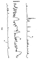
- a lamp emitting a concentrated light beam was fixed to the instep of a foot of a test person standing on the mat to be tested in an upright position and reading a book.
- the lamp was fixed to the foot in such a manner that the light beam was parallel to the longitudinal axis of the foot and thus reflected movements of the instep in a vertical plane through the longitudinal axis of the foot.
- the movements of the light beam were recorded on a moving chart placed in front of the test person.
- Curves a and b illustrate the movements of a test person standing on the prior art mat and the mat according to the invention respectively whereas curve c illustrates the movements of a person standing directly on a concrete floor.
- the mat of the invention causes a test person to change position repeatedly whereas he is standing essentially still over relatively long periods when he is standing on the prior art mat or on a concrete floor.
Landscapes
- Health & Medical Sciences (AREA)
- Chemical & Material Sciences (AREA)
- Dispersion Chemistry (AREA)
- Rehabilitation Therapy (AREA)
- Animal Behavior & Ethology (AREA)
- Pain & Pain Management (AREA)
- Physical Education & Sports Medicine (AREA)
- Life Sciences & Earth Sciences (AREA)
- General Health & Medical Sciences (AREA)
- Public Health (AREA)
- Veterinary Medicine (AREA)
- Epidemiology (AREA)
- Mattresses And Other Support Structures For Chairs And Beds (AREA)
- Invalid Beds And Related Equipment (AREA)
- Carpets (AREA)
- Laminated Bodies (AREA)
- Pharmaceuticals Containing Other Organic And Inorganic Compounds (AREA)
- Nitrogen Condensed Heterocyclic Rings (AREA)
- Blow-Moulding Or Thermoforming Of Plastics Or The Like (AREA)
- Dowels (AREA)
- Finger-Pressure Massage (AREA)
- Absorbent Articles And Supports Therefor (AREA)
- Floor Finish (AREA)
- Footwear And Its Accessory, Manufacturing Method And Apparatuses (AREA)
Priority Applications (1)
| Application Number | Priority Date | Filing Date | Title |
|---|---|---|---|
| AT88112892T ATE87805T1 (de) | 1987-08-14 | 1988-08-08 | Verfahren zur herstellung eines dauerhaft formstabilen und elastischen gegenstandes. |
Applications Claiming Priority (2)
| Application Number | Priority Date | Filing Date | Title |
|---|---|---|---|
| DK4260/87 | 1987-08-14 | ||
| DK426087A DK157725C (da) | 1987-08-14 | 1987-08-14 | Maatte til understoetning af en person i oprejst stilling og fremgangsmaade til fremstilling af samme |
Publications (3)
| Publication Number | Publication Date |
|---|---|
| EP0303219A2 true EP0303219A2 (de) | 1989-02-15 |
| EP0303219A3 EP0303219A3 (en) | 1989-06-07 |
| EP0303219B1 EP0303219B1 (de) | 1993-04-07 |
Family
ID=8131838
Family Applications (1)
| Application Number | Title | Priority Date | Filing Date |
|---|---|---|---|
| EP88112892A Expired - Lifetime EP0303219B1 (de) | 1987-08-14 | 1988-08-08 | Verfahren zur Herstellung eines dauerhaft formstabilen und elastischen Gegenstandes |
Country Status (12)
| Country | Link |
|---|---|
| US (1) | US5108690A (de) |
| EP (1) | EP0303219B1 (de) |
| JP (1) | JPH01206031A (de) |
| KR (1) | KR890003350A (de) |
| AT (1) | ATE87805T1 (de) |
| AU (1) | AU616192B2 (de) |
| BR (1) | BR8804085A (de) |
| CA (1) | CA1303324C (de) |
| DE (1) | DE3880044T2 (de) |
| DK (1) | DK157725C (de) |
| MX (1) | MX169358B (de) |
| ZA (1) | ZA885883B (de) |
Families Citing this family (2)
| Publication number | Priority date | Publication date | Assignee | Title |
|---|---|---|---|---|
| US6649237B1 (en) * | 1999-10-18 | 2003-11-18 | Phoenix Ag | Mat consisting of tubes |
| US20040091674A1 (en) * | 2002-11-12 | 2004-05-13 | 3M Innovative Properties Company | Mat with elastic compressible elements |
Family Cites Families (6)
| Publication number | Priority date | Publication date | Assignee | Title |
|---|---|---|---|---|
| NL6807357A (de) * | 1967-06-01 | 1968-12-02 | ||
| US3739055A (en) * | 1969-08-26 | 1973-06-12 | Bridgestone Tire Co Ltd | Method for heat treating polyamide fibers |
| JPS4826861A (de) * | 1971-08-12 | 1973-04-09 | ||
| SE7411960L (sv) * | 1974-09-24 | 1976-03-25 | Fabriker As Haustrups | Sett att framstella behallare sasom flaskor eller burkar av polyester |
| US4247514A (en) * | 1975-05-05 | 1981-01-27 | E. I. Du Pont De Nemours And Company | Process for strengthening a shaped article of a polyester |
| DK158249C (da) * | 1984-07-24 | 1990-09-24 | Cellastic As | Fjedrende understoetningsorgan, isaer i form af en madras, et saede, en pude eller lignende |
-
1987
- 1987-08-14 DK DK426087A patent/DK157725C/da not_active IP Right Cessation
-
1988
- 1988-08-08 DE DE8888112892T patent/DE3880044T2/de not_active Expired - Fee Related
- 1988-08-08 AT AT88112892T patent/ATE87805T1/de not_active IP Right Cessation
- 1988-08-08 EP EP88112892A patent/EP0303219B1/de not_active Expired - Lifetime
- 1988-08-10 ZA ZA885883A patent/ZA885883B/xx unknown
- 1988-08-10 AU AU20597/88A patent/AU616192B2/en not_active Ceased
- 1988-08-12 CA CA000574557A patent/CA1303324C/en not_active Expired - Fee Related
- 1988-08-12 BR BR8804085A patent/BR8804085A/pt unknown
- 1988-08-13 KR KR1019880010329A patent/KR890003350A/ko not_active Withdrawn
- 1988-08-15 JP JP63203064A patent/JPH01206031A/ja active Pending
- 1988-08-15 MX MX012683A patent/MX169358B/es unknown
-
1990
- 1990-10-15 US US07/597,797 patent/US5108690A/en not_active Expired - Fee Related
Also Published As
| Publication number | Publication date |
|---|---|
| US5108690A (en) | 1992-04-28 |
| ZA885883B (en) | 1989-04-26 |
| DE3880044T2 (de) | 1993-09-16 |
| DK157725B (da) | 1990-02-12 |
| MX169358B (es) | 1993-06-30 |
| AU2059788A (en) | 1989-02-16 |
| DK157725C (da) | 1990-07-09 |
| ATE87805T1 (de) | 1993-04-15 |
| BR8804085A (pt) | 1989-03-07 |
| CA1303324C (en) | 1992-06-16 |
| AU616192B2 (en) | 1991-10-24 |
| KR890003350A (ko) | 1989-04-14 |
| JPH01206031A (ja) | 1989-08-18 |
| EP0303219B1 (de) | 1993-04-07 |
| DK426087A (da) | 1989-02-15 |
| DK426087D0 (da) | 1987-08-14 |
| EP0303219A3 (en) | 1989-06-07 |
| DE3880044D1 (de) | 1993-05-13 |
Similar Documents
| Publication | Publication Date | Title |
|---|---|---|
| US4183156A (en) | Insole construction for articles of footwear | |
| CA2322405C (en) | Work insoles | |
| CA2349272C (en) | Full length insole for arthritic and/or diabetic people | |
| KR940004750B1 (ko) | 운동화 | |
| US6178662B1 (en) | Dispersed-air footpad | |
| US6915598B2 (en) | Insole with arch spring | |
| CA2514278C (en) | Heel insert | |
| US4219945A (en) | Footwear | |
| US4451994A (en) | Resilient midsole component for footwear | |
| US20130062922A1 (en) | Leg Elevation Device | |
| MXPA02007349A (es) | Plantilla para caminata recreativa y para el buen estado fisico. | |
| US20080028625A1 (en) | Apparatus and Method for Replicating a Plantar Surface of a Foot | |
| US5108690A (en) | Mat for supporting a person in an upright position and process for obtaining a resilient article having a static module which is stable over a long period | |
| US20090215016A1 (en) | Device for the determination of parameters particularly for therapeutic compression means on limbs | |
| US10653573B2 (en) | Fitting system and method for modular pressure relief cushion | |
| KR830002612B1 (ko) | 신발류의 팽창 인서어트 구조물 | |
| WO1990000021A1 (en) | Footwear | |
| RU2654651C1 (ru) | Индивидуальная ортопедическая стелька и способ её изготовления | |
| Pratt | Polyurethanes in orthotics and orthopaedics | |
| CA1226732A (en) | Shoe insole | |
| HK1037492A (en) | Work insoles | |
| ITMI20122025A1 (it) | Plateau con camera interna a riempimento ammortizzatore per calzature e calzatura dotata di detto plateau | |
| HK1079061A (en) | Removable insole and footwear provided with an insole |
Legal Events
| Date | Code | Title | Description |
|---|---|---|---|
| PUAI | Public reference made under article 153(3) epc to a published international application that has entered the european phase |
Free format text: ORIGINAL CODE: 0009012 |
|
| AK | Designated contracting states |
Kind code of ref document: A2 Designated state(s): AT BE CH DE ES FR GB GR IT LI LU NL SE |
|
| PUAL | Search report despatched |
Free format text: ORIGINAL CODE: 0009013 |
|
| AK | Designated contracting states |
Kind code of ref document: A3 Designated state(s): AT BE CH DE ES FR GB GR IT LI LU NL SE |
|
| 17P | Request for examination filed |
Effective date: 19890825 |
|
| 17Q | First examination report despatched |
Effective date: 19911227 |
|
| GRAA | (expected) grant |
Free format text: ORIGINAL CODE: 0009210 |
|
| AK | Designated contracting states |
Kind code of ref document: B1 Designated state(s): AT BE CH DE ES FR GB GR IT LI LU NL SE |
|
| PG25 | Lapsed in a contracting state [announced via postgrant information from national office to epo] |
Ref country code: IT Free format text: LAPSE BECAUSE OF FAILURE TO SUBMIT A TRANSLATION OF THE DESCRIPTION OR TO PAY THE FEE WITHIN THE PRE;WARNING: LAPSES OF ITALIAN PATENTS WITH EFFECTIVE DATE BEFORE 2007 MAY HAVE OCCURRED AT ANY TIME BEFORE 2007. THE CORRECT EFFECTIVE DATE MAY BE DIFFERENT FROM THE ONE RECORDED.SCRIBED TIME-LIMIT Effective date: 19930407 Ref country code: FR Effective date: 19930407 Ref country code: GR Free format text: LAPSE BECAUSE OF FAILURE TO SUBMIT A TRANSLATION OF THE DESCRIPTION OR TO PAY THE FEE WITHIN THE PRESCRIBED TIME-LIMIT Effective date: 19930407 Ref country code: NL Effective date: 19930407 Ref country code: LI Effective date: 19930407 Ref country code: AT Effective date: 19930407 Ref country code: CH Effective date: 19930407 Ref country code: BE Effective date: 19930407 Ref country code: ES Free format text: THE PATENT HAS BEEN ANNULLED BY A DECISION OF A NATIONAL AUTHORITY Effective date: 19930407 |
|
| REF | Corresponds to: |
Ref document number: 87805 Country of ref document: AT Date of ref document: 19930415 Kind code of ref document: T |
|
| REF | Corresponds to: |
Ref document number: 3880044 Country of ref document: DE Date of ref document: 19930513 |
|
| REG | Reference to a national code |
Ref country code: CH Ref legal event code: PL |
|
| EN | Fr: translation not filed | ||
| PG25 | Lapsed in a contracting state [announced via postgrant information from national office to epo] |
Ref country code: LU Free format text: LAPSE BECAUSE OF NON-PAYMENT OF DUE FEES Effective date: 19930831 |
|
| NLV1 | Nl: lapsed or annulled due to failure to fulfill the requirements of art. 29p and 29m of the patents act | ||
| PLBE | No opposition filed within time limit |
Free format text: ORIGINAL CODE: 0009261 |
|
| STAA | Information on the status of an ep patent application or granted ep patent |
Free format text: STATUS: NO OPPOSITION FILED WITHIN TIME LIMIT |
|
| 26N | No opposition filed | ||
| PGFP | Annual fee paid to national office [announced via postgrant information from national office to epo] |
Ref country code: GB Payment date: 19940826 Year of fee payment: 7 |
|
| PGFP | Annual fee paid to national office [announced via postgrant information from national office to epo] |
Ref country code: SE Payment date: 19940831 Year of fee payment: 7 |
|
| PGFP | Annual fee paid to national office [announced via postgrant information from national office to epo] |
Ref country code: DE Payment date: 19941031 Year of fee payment: 7 |
|
| EAL | Se: european patent in force in sweden |
Ref document number: 88112892.0 |
|
| PG25 | Lapsed in a contracting state [announced via postgrant information from national office to epo] |
Ref country code: GB Effective date: 19950808 |
|
| PG25 | Lapsed in a contracting state [announced via postgrant information from national office to epo] |
Ref country code: SE Effective date: 19950809 |
|
| GBPC | Gb: european patent ceased through non-payment of renewal fee |
Effective date: 19950808 |
|
| PG25 | Lapsed in a contracting state [announced via postgrant information from national office to epo] |
Ref country code: DE Effective date: 19960501 |
|
| EUG | Se: european patent has lapsed |
Ref document number: 88112892.0 |