EP0302995A1 - Magnetic shunt for deflection yokes - Google Patents
Magnetic shunt for deflection yokes Download PDFInfo
- Publication number
- EP0302995A1 EP0302995A1 EP88105077A EP88105077A EP0302995A1 EP 0302995 A1 EP0302995 A1 EP 0302995A1 EP 88105077 A EP88105077 A EP 88105077A EP 88105077 A EP88105077 A EP 88105077A EP 0302995 A1 EP0302995 A1 EP 0302995A1
- Authority
- EP
- European Patent Office
- Prior art keywords
- ring
- screen
- coil
- field
- magnetic field
- Prior art date
- Legal status (The legal status is an assumption and is not a legal conclusion. Google has not performed a legal analysis and makes no representation as to the accuracy of the status listed.)
- Granted
Links
Images


Classifications
-
- H—ELECTRICITY
- H01—ELECTRIC ELEMENTS
- H01J—ELECTRIC DISCHARGE TUBES OR DISCHARGE LAMPS
- H01J29/00—Details of cathode-ray tubes or of electron-beam tubes of the types covered by group H01J31/00
- H01J29/46—Arrangements of electrodes and associated parts for generating or controlling the ray or beam, e.g. electron-optical arrangement
- H01J29/70—Arrangements for deflecting ray or beam
-
- H—ELECTRICITY
- H01—ELECTRIC ELEMENTS
- H01J—ELECTRIC DISCHARGE TUBES OR DISCHARGE LAMPS
- H01J29/00—Details of cathode-ray tubes or of electron-beam tubes of the types covered by group H01J31/00
- H01J29/003—Arrangements for eliminating unwanted electromagnetic effects, e.g. demagnetisation arrangements, shielding coils
-
- H—ELECTRICITY
- H01—ELECTRIC ELEMENTS
- H01J—ELECTRIC DISCHARGE TUBES OR DISCHARGE LAMPS
- H01J2229/00—Details of cathode ray tubes or electron beam tubes
- H01J2229/0007—Elimination of unwanted or stray electromagnetic effects
- H01J2229/0015—Preventing or cancelling fields leaving the enclosure
Definitions
- the present invention relates to display apparatus, and more particularly relates to apparatus for reducing unwanted magnetic radiation external to a cathode ray tube display device, in front of the screen thereof.
- CRTs Cathode Ray Tubes
- CTRs Cathode Ray Tubes
- yokes In addition to manifesting itself within the CRT, for beam deflection, this magnetic field also extends outside of the CRT, and even in front of the screen. This external magnetic field serves no useful purpose and an effort is frequently made to reduce this part of the yoke magnetic field.
- the present invention provides a cathode ray tube apparatus including means for reducing magnetic radiation in front of a viewing screen of the cathode ray tube comprising the viewing screen, means for producing a charged particle beam directed at the screen from the rear thereof and a deflection coil disposed behind the screen for deflecting the beam across the screen, characterised in that the means for reducing magnetic radiation in front of the viewing screen comprises magnetic shunt means disposed between the coil and the screen.
- the present invention finds application in a cathode ray apparatus including a cathode ray tube ("CRT") having a screen for viewing and having a charged particle beam directed at the screen from the rear thereof and aligned with the central axis of the tube, but that may be magnetically deflected from the axis, and having a deflection coil producing a magnetic component from axially aligned wire segments and a magnetic component from circumferentially aligned wire segments relative to the axis, giving rise to a net distributed magnetic field in front of the coil.
- CTR cathode ray tube
- the apparatus reduces the net distributed magnetic radiation in front of the coil through the provision of a magnetic shunt disposed between the coil and the screen, wherein the magnetic shunt comprises a magnetically permeable material having its configuration and position relative to the coil selected to minimize the net distributed magnetic field in front of the coil.
- the invention may be embodied in forms which are made of relatively inexpensive linear ferrite materials configured in shapes that are inexpensive to provide, such as a flat ring or the like. As such, it permits a relatively inexpensive solution to the problem. In addition, in tested embodiments the present invention has demonstrated dramatic reductions in the unwanted radiation in front of CRTs to which it has been applied.
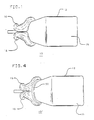
- Fig. 1 shows the pertinent portions of an integrated yoke tube component (“ITC") 10 which includes a CRT 12, having a front screen 14, and upper and lower horizontal deflection coils 16, 18.
- the deflection coils 16, 18 generate a varying magnetic field between them, inside CRT 12, to deflect the electron beam within the tube 12 for horizontal sweeping across the face of the screen 14, as is well known in the art.
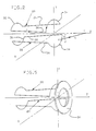
- Fig. 2 is a simplified diagram of one winding each from the upper and lower deflection coils 16, 18, of Fig. 1.
- loop 20 is a single loop from coil 16
- loop 22 is a single loop from coil 18.
- a current i flows through each of the coils so as to generate the above described varying magnetic field for horizontal deflection of the electron beam.
- the useful portion of the loops 20, 22 are the axially aligned portions thereof 24, 26, 28, 30, which produce the main deflection field.
- the circumferentially aligned portions of the loop (end turns) 32, 34, 36, 38 serve only to complete the circuit of each of the respective loops 20, 22, and are otherwise unnecessary for the operation of the deflection coils 16, 18.
- These circumferentially aligned coil portions 32, 34, 36, 38 contribute the major portion of the residual distributed magnetic field that extends a significant distance in front of the screen 14 (Fig. 1) which is to be reduced.
- the residual field is the vector sum of the main deflection field and the end turn field.
- the resulting sum will follow the polarity of the end turn field, since the end turn component is the larger, and both decay at the same rate with distance.
- X, Y, and Z axes are depicted, having their origin in the plane of circumferential coil portions 34, 38 and centrally located between them.
- the Z axis coincides with the central axis of CRT 12 (Fig. 1). Note that the upper and lower halves 20, 22 are symmetrical about the x-z and y-z planes.
- the upper and lower loops 20, 22 are interconnected to produce a dipole field on the Z axis, as is known.
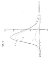
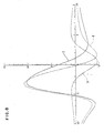
- the B field is given by: where J is the current, R is the direction and R is the distance to a point of interest T on the Z axis.
- the actual B field is a directional field, and the plot shown in Fig. 3 shows only the magnitude, or intensity, of such magnetic field along the Z axis.
- the units depicted on the horizontal axis are centimeters, while the units in the vertical axis are gauss.
- the curve reflects a typical coil having current flowing so as to produce a field which deflects a 20 kilovolt electron beam to an angle of about 40 degrees.
- Curves A, B, and C of Fig. 3 represent the total field, the partial field from the axial wires and the partial field from the end turns, respectively.
- Curve A is the magnitude of the vector sum of the fields represented by curves B and C.
- the field can be in range of approximately 1,000 - 2,000 nano-Tesla.
- this field can be reduced to an even smaller quantity. In actual experiments using the preferred embodiment described below, reductions to below 200 nano-tesla at 55 centimeters was measured.
- Fig. 4 shows the ITC 10 of Fig. 1 having added thereto a ring 50 of linear ferrite operating as a magnetic shunt, in accordance with the preferred embodiment of the present invention.
- Fig. 5 shows the loops 20, 22 of Fig. 2, with the ferrite ring 50 disposed in front of it, to illustrate the relative shape and position of ring 50.
- Ring 50 is a linear ferrite.
- Linear ferrite is a well known material commonly used in transformer and yoke production.
- the ring 50 has a relatively high magnetic permeability, or mu. It also has a high volume resistivity, or rho, for example 1 Meg Ohm or more per cubic centimeter The high rho value keeps eddy currents at a minimum.
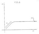
- a value of 1,000 represents a point such as point 52 for a linear ferrite ring having dimensions typical for the application described herein. If a mu value of, for example, 10 were selected, it would be in the sloping area 53 of the curve shown in Fig. 6.
- Such a material would be highly susceptible to variations in manufacturing tolerances, temperature of operation, and the like, and would therefore provide erratic performance depending upon the variation of these factors.
- the permeability By selecting the permeability to be in the flat, horizontal area of the curve of Fig. 6, the above described undesirable variations in performance are substantially avoided.
- the material cost considerations will tend to keep the permeability of the material low within the range of acceptable permeability for providing this preferred stability.
- Fig. 7 is a set of curves, on the same set of axes as these of Fig. 3, showing the effect on the net field A shown in Fig. 3 of a flat ring, such as ring 50 in Fig. 4, in accordance with the preferred embodiment of the present invention.
- Curve A in Fig. 7 is the same as curve A in Fig. 3.
- Curve D in Fig. 7 represents the field contribution from the magnetization effect of the ring 50, while curve E represents the resultant curve from the combination of curves A and D.
- Fig. 8 a set of curves is shown in Fig. 8 including curve D, the magnetic field from the ring, and two other curves which help in this understanding.
- Curve C is the same curve C as is shown in Fig. 3.
- Curve F is a curve representing the resultant field from the combination of curves D and C. Note that in Fig. 8 the horizontal axis is the same as that of curves 3 and 7 while the vertical field has been expanded, to aid in clarity.
- curve D is the theoretical field of the ring alone. This is an intrinsic field which is created by the magnetisation force of the end turn field. It should be noted that the presence of the ring attenuates the end turn field. The degree of attenuation is controlled by the variables such as ring dimensions and ring yoke separation, as is discussed in more detail below. It should be further noted that the end turn field combines with the main deflection field, and the area in front of the CRT screen, to form the net measurable residual field whose reduction is an object of this invention. At optimum attenuation, the modified end turn field F is equal in magnitude but opposite in direction to the main deflection field, resulting in a zero vector sum. As a practical matter, the net measurable residual field in front of the CRT screen can never be reduced to zero. However, by application of the principles of the present invention as disclosed herein, this field can be reduced to very small levels.
- Fig. 7 The portion of Fig. 7 beyond approximately 2.5 centimeters to the right thereof is shown in Fig. 9. In order to see clearly the curve behaviour in that region, the scale is expanded in the vertical direction as compared with Fig. 7. Curves A and E are as described in Fig. 7. Curve D is not shown in this figure in the interest of providing more clarity for curves A and E. Note that Curve E is very nearly at a zero field magnitude at approximately 9.5 centimeters.
- the compensated curve E for a typical CRT-yoke configuration is shown, where the ring 50 is of ferrite with a permeability of 1,000 -3,000, and a rho of 1 meg ohm per cubic centimeter or more, and having an inner dimension of 4 centimeters, a thickness of .2 centimeters, a width of 1 centimeter, placed at a distance of .4 centimeters from the end of the yoke.
- the width of the ring refers to its radial extent from inner diameter to outer diameter.
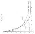
- Figs. 10-12 are plots like the plot shown in Fig. 9, for slightly different ring configurations from the configuration producing the curves of Fig. 9.
- all of the parameters for the ring are the same as those corresponding to Fig. 9, except the distance of the ring from the end of the yoke.
- the curves correspond to a configuration in which this dimension is .3 centimeters. It will be appreciated that this reveals over-compensation, as the curve E′ is slightly farther from the horizontal axis, for example at 9.5 centimeters.
- Fig. 11 The curves of Fig. 11 are for a configuration in which the dimensions are the same as those corresponding to Fig. 9, but wherein the inner diameter radius is 5 centimeters, instead of 4 centimeters. It can be seen that significantly less compensation is provided, as curve E ⁇ is here below the horizontal axis, and by an amount greater than curve E is above the horizontal axis, at 9.5 centimeters.
- Fig. 12 shows a curve for a configuration wherein the dimensions are as in Fig. 9, but wherein the distance of the ring from the end of the yoke is .6 centimeters, instead of .4 centimeters. It can be seen that slightly less compensation is provided, causing curve E′′′ to cross the horizontal axis at 9.5 centimeters. This was deemed to represent optimum compensation.
- a ferrite ring of ordinary linear ferrite was provided, having a mu of approximately 1,000 - 3,000 and a rho of greater than 1 meg ohm per cc, ring dimensions of: an inner dimension of 4-3/8", a width of 3/8", and a thickness of 1/8". This ring was found to produce excellent cancellation effects when it was placed against the circumferential wire portions of the yoke provided with this ITC with spacing resulting only from the insulation of the yoke wires.
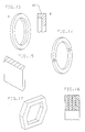
- a ring having a lip portion 62 may be employed to advantage, the lip 62 being believed to serve to enhance the cancellation of the undesired field.
- the additional machining required to make the configuration shown in Fig. 13 results in a more costly article than ring 50.
- FIG. 14 Another alternative configuration is that of a ring formed from two portions, such as is shown in Fig. 14.
- a ring configuration having a cross section such as is shown in Fig. 15 is also possible. It is believed that this configuration also provides beneficial cancellation field shaping characteristics. However, it also represents a more costly article than a simple flat ferrite ring such as described above.
- Fig. 17 shows a hexagonally shaped ring, representing a still further embodiment for use with, for example, a hexagonally configured yoke.
- embodiments may be made with conventional mu metal laminates, yielding rings having a cross-section as shown in Fig. 16.
Abstract
Description
- The present invention relates to display apparatus, and more particularly relates to apparatus for reducing unwanted magnetic radiation external to a cathode ray tube display device, in front of the screen thereof.
- Cathode Ray Tubes ("CRTs") generally have associated coils, or yokes, to provide a varying magnetic field for electron beam deflection, for example for raster scan. In addition to manifesting itself within the CRT, for beam deflection, this magnetic field also extends outside of the CRT, and even in front of the screen. This external magnetic field serves no useful purpose and an effort is frequently made to reduce this part of the yoke magnetic field.
- Means to provide this reduction have been proposed in the prior art. For example, one such proposal is the provision of Helmholtz coils disposed "on top of", or radially away from and adjacent to the saddle-shaped deflection yoke. The coils are coupled to the deflection coils and the EMF is induced therein, giving rise to a magnetic field which tends to cancel the residual magnetic field in front of the screen. However, this is a relatively expensive and bulky solution to the problem.
- Another proposed solution is the placement of shielding all around the CRT, which results in magnetic radiation reduction from the eddy currents induced in the shielding. However, this is also an expensive solution to the problem, and results in only minimal reduction in the magnetic field in front of the screen.
- There is therefore a need for means to reduce to acceptable levels the residual magnetic field in front of the cathode ray tube display device that provides an inexpensive and compact solution to the problem.
- Accordingly, the present invention provides a cathode ray tube apparatus including means for reducing magnetic radiation in front of a viewing screen of the cathode ray tube comprising the viewing screen, means for producing a charged particle beam directed at the screen from the rear thereof and a deflection coil disposed behind the screen for deflecting the beam across the screen, characterised in that the means for reducing magnetic radiation in front of the viewing screen comprises magnetic shunt means disposed between the coil and the screen.
- The present invention finds application in a cathode ray apparatus including a cathode ray tube ("CRT") having a screen for viewing and having a charged particle beam directed at the screen from the rear thereof and aligned with the central axis of the tube, but that may be magnetically deflected from the axis, and having a deflection coil producing a magnetic component from axially aligned wire segments and a magnetic component from circumferentially aligned wire segments relative to the axis, giving rise to a net distributed magnetic field in front of the coil. The apparatus reduces the net distributed magnetic radiation in front of the coil through the provision of a magnetic shunt disposed between the coil and the screen, wherein the magnetic shunt comprises a magnetically permeable material having its configuration and position relative to the coil selected to minimize the net distributed magnetic field in front of the coil.
- The invention may be embodied in forms which are made of relatively inexpensive linear ferrite materials configured in shapes that are inexpensive to provide, such as a flat ring or the like. As such, it permits a relatively inexpensive solution to the problem. In addition, in tested embodiments the present invention has demonstrated dramatic reductions in the unwanted radiation in front of CRTs to which it has been applied.
-
- Fig. 1 is a diagram showing pertinent portions of an integrated yoke tube component.
- Fig. 2 is a simplified diagram of one winding each from the upper and lower deflection coils of the integrated yoke tube component shown in Fig. 1.
- Fig. 3 is a plot showing the magnetic field intensity along the Z axis for a typical deflection yoke such as is shown in Fig. 1.
- Fig. 4 is a figure like that of Fig. 1, having added thereto a
ring 50 in accordance with the preferred embodiment of the present invention. - Fig. 5 is a diagram like that of Fig. 2, having added thereto a
ring 50 in accordance with the preferred embodiment of the present invention. - Fig. 6 is a plot showing the effective mu vs. actual mu for the ring depicted in Figs. 4 and 5.
- Fig. 7 is a set of curves, on the same set of axes as in Fig. 3, showing the effect on the net field A of
ring 50. - Fig. 8 is a set of curves showing the effect of
ring 50 on the end turn field shown in Fig. 3. - Fig. 9 is an expanded view of the portion of the curve shown in Fig. 7 beyond approximately 2.5 centimeters.
- Fig. 10 is a plot like that of Fig. 9, wherein
ring 50 is a slightly different distance from the yoke. - Fig. 11 is a diagram like Fig. 9, in which the inner diameter radius of
ring 50 is slightly different from that of Fig. 9. - Fig. 12 is a curve like that of Fig. 9 but wherein the distance of the
ring 50 from the end of the yoke is different from that of Fig. 9 and Fig. 10. - Fig. 13 is a diagram of a further embodiment, which includes a
lip portion 62. - Fig. 14 shows a still further embodiment in which a ring is provided having two portions.
- Fig. 15 shows a still further embodiment made by injection molding techniques of a material such as nylon impregnated with ferrite particles.
- Fig. 16 is a cross-sectional diagram through a portion of a still further embodiment of ring, made with conventional mu metal laminates.
- Fig. 17 shows a further embodiment, having a hexagonal shape.
- Fig. 1 shows the pertinent portions of an integrated yoke tube component ("ITC") 10 which includes a
CRT 12, having afront screen 14, and upper and lowerhorizontal deflection coils deflection coils CRT 12, to deflect the electron beam within thetube 12 for horizontal sweeping across the face of thescreen 14, as is well known in the art. - Fig. 2 is a simplified diagram of one winding each from the upper and
lower deflection coils loop 20 is a single loop fromcoil 16, whileloop 22 is a single loop fromcoil 18. As illustrated, a current i flows through each of the coils so as to generate the above described varying magnetic field for horizontal deflection of the electron beam. The useful portion of theloops - The circumferentially aligned portions of the loop (end turns) 32, 34, 36, 38 serve only to complete the circuit of each of the
respective loops deflection coils coil portions - In Fig. 2, X, Y, and Z axes are depicted, having their origin in the plane of
circumferential coil portions lower halves - In actual operation the upper and
lower loops B field is given by:
J is the current,R is the direction and R is the distance to a point of interest T on the Z axis. - A plot of the
B field distribution of a typical horizontal deflection coil, such as is shown in Fig. 1, shielded with high permeability material, like ferrite, is shown in Fig. 3. The actualB field is a directional field, and the plot shown in Fig. 3 shows only the magnitude, or intensity, of such magnetic field along the Z axis. The units depicted on the horizontal axis are centimeters, while the units in the vertical axis are gauss. The curve reflects a typical coil having current flowing so as to produce a field which deflects a 20 kilovolt electron beam to an angle of about 40 degrees. - Curves A, B, and C of Fig. 3 represent the total field, the partial field from the axial wires and the partial field from the end turns, respectively. Curve A is the magnitude of the vector sum of the fields represented by curves B and C. In typical uncompensated yokes, at 55 centimeters in front of the yoke the field can be in range of approximately 1,000 - 2,000 nano-Tesla. Clearly, this is not a very large magnetic field. However, in accordance with the present invention this field can be reduced to an even smaller quantity. In actual experiments using the preferred embodiment described below, reductions to below 200 nano-tesla at 55 centimeters was measured.
- Fig. 4 shows the ITC 10 of Fig. 1 having added thereto a
ring 50 of linear ferrite operating as a magnetic shunt, in accordance with the preferred embodiment of the present invention. - Fig. 5 shows the
loops ferrite ring 50 disposed in front of it, to illustrate the relative shape and position ofring 50. -
Ring 50, as mentioned above, is a linear ferrite. Linear ferrite is a well known material commonly used in transformer and yoke production. According to the preferred embodiment thering 50 has a relatively high magnetic permeability, or mu. It also has a high volume resistivity, or rho, for example 1 Meg Ohm or more per cubic centimeter The high rho value keeps eddy currents at a minimum. - Otherwise the loading effects on the yoke would result in a need for more energy to drive the yoke. While embodiments could be constructed, for example out of conventional mu metal laminates, having this loading effect, and be in accordance with the present invention, it was deemed desirable to keep the eddy currents low, and avoid this loading effect in the preferred embodiment. The cross section of the
ring 50 is large enough to avoid saturation. - Referring to Fig. 6 a plot is shown of the variation of effective mu, mue versus actual mu, mua, for a ring such as
ring 50 positioned in front ofcoils point 52 for a linear ferrite ring having dimensions typical for the application described herein. If a mu value of, for example, 10 were selected, it would be in the slopingarea 53 of the curve shown in Fig. 6. Such a material would be highly susceptible to variations in manufacturing tolerances, temperature of operation, and the like, and would therefore provide erratic performance depending upon the variation of these factors. By selecting the permeability to be in the flat, horizontal area of the curve of Fig. 6, the above described undesirable variations in performance are substantially avoided. However, the material cost considerations will tend to keep the permeability of the material low within the range of acceptable permeability for providing this preferred stability. - Fig. 7 is a set of curves, on the same set of axes as these of Fig. 3, showing the effect on the net field A shown in Fig. 3 of a flat ring, such as
ring 50 in Fig. 4, in accordance with the preferred embodiment of the present invention. Curve A in Fig. 7 is the same as curve A in Fig. 3. Curve D in Fig. 7 represents the field contribution from the magnetization effect of thering 50, while curve E represents the resultant curve from the combination of curves A and D. - To better understand the effect of the field from the ring on the overall magnetic field A, a set of curves is shown in Fig. 8 including curve D, the magnetic field from the ring, and two other curves which help in this understanding. Curve C is the same curve C as is shown in Fig. 3. Curve F is a curve representing the resultant field from the combination of curves D and C. Note that in Fig. 8 the horizontal axis is the same as that of
curves - As mentioned above, curve D is the theoretical field of the ring alone. This is an intrinsic field which is created by the magnetisation force of the end turn field. It should be noted that the presence of the ring attenuates the end turn field. The degree of attenuation is controlled by the variables such as ring dimensions and ring yoke separation, as is discussed in more detail below. It should be further noted that the end turn field combines with the main deflection field, and the area in front of the CRT screen, to form the net measurable residual field whose reduction is an object of this invention. At optimum attenuation, the modified end turn field F is equal in magnitude but opposite in direction to the main deflection field, resulting in a zero vector sum. As a practical matter, the net measurable residual field in front of the CRT screen can never be reduced to zero. However, by application of the principles of the present invention as disclosed herein, this field can be reduced to very small levels.
- The portion of Fig. 7 beyond approximately 2.5 centimeters to the right thereof is shown in Fig. 9. In order to see clearly the curve behaviour in that region, the scale is expanded in the vertical direction as compared with Fig. 7. Curves A and E are as described in Fig. 7. Curve D is not shown in this figure in the interest of providing more clarity for curves A and E. Note that Curve E is very nearly at a zero field magnitude at approximately 9.5 centimeters.
- The compensated curve E for a typical CRT-yoke configuration is shown, where the
ring 50 is of ferrite with a permeability of 1,000 -3,000, and a rho of 1 meg ohm per cubic centimeter or more, and having an inner dimension of 4 centimeters, a thickness of .2 centimeters, a width of 1 centimeter, placed at a distance of .4 centimeters from the end of the yoke. As used herein, the width of the ring refers to its radial extent from inner diameter to outer diameter. - Figs. 10-12 are plots like the plot shown in Fig. 9, for slightly different ring configurations from the configuration producing the curves of Fig. 9. Thus, in Fig. 10 all of the parameters for the ring are the same as those corresponding to Fig. 9, except the distance of the ring from the end of the yoke. In Fig. 10 the curves correspond to a configuration in which this dimension is .3 centimeters. It will be appreciated that this reveals over-compensation, as the curve E′ is slightly farther from the horizontal axis, for example at 9.5 centimeters.
- The curves of Fig. 11 are for a configuration in which the dimensions are the same as those corresponding to Fig. 9, but wherein the inner diameter radius is 5 centimeters, instead of 4 centimeters. It can be seen that significantly less compensation is provided, as curve E˝ is here below the horizontal axis, and by an amount greater than curve E is above the horizontal axis, at 9.5 centimeters.
- Fig. 12 shows a curve for a configuration wherein the dimensions are as in Fig. 9, but wherein the distance of the ring from the end of the yoke is .6 centimeters, instead of .4 centimeters. It can be seen that slightly less compensation is provided, causing curve E‴ to cross the horizontal axis at 9.5 centimeters. This was deemed to represent optimum compensation.
- While curves are not provided showing the effect of change of width of the ring on the compensation effect, in general, decreasing the width will tend to reduce the compensating effect, while increasing the width will tend to increase the effect.
- Thus, from the above Figs. 9-12, it will be appreciated that changing the various dimensional parameters of the preferred embodiment of the present invention affects the performance of the ring in compensating by cancelling the magnetic field components on the Z axis in front of the screen due to yoke winding components. Through an understanding of these effects, one practicing the present invention can provide the adjustments deemed desirable to optimize the cancellation effect.
- In an actual prototype experiment, in conjunction with an ITC manufactured by Matsushita Company having a series number of M34JDJ00X01, a ferrite ring of ordinary linear ferrite was provided, having a mu of approximately 1,000 - 3,000 and a rho of greater than 1 meg ohm per cc, ring dimensions of: an inner dimension of 4-3/8", a width of 3/8", and a thickness of 1/8". This ring was found to produce excellent cancellation effects when it was placed against the circumferential wire portions of the yoke provided with this ITC with spacing resulting only from the insulation of the yoke wires.
- It should be noted that other configurations in accordance with the present invention may be used. For example, as shown in Fig. 13, a ring having a
lip portion 62, may be employed to advantage, thelip 62 being believed to serve to enhance the cancellation of the undesired field. However, the additional machining required to make the configuration shown in Fig. 13 results in a more costly article thanring 50. - Another alternative configuration is that of a ring formed from two portions, such as is shown in Fig. 14.
- Further, using injection molding techniques, for example with nylon impregnated with ferrite particles, a ring configuration having a cross section, such as is shown in Fig. 15 is also possible. It is believed that this configuration also provides beneficial cancellation field shaping characteristics. However, it also represents a more costly article than a simple flat ferrite ring such as described above.
- Fig. 17 shows a hexagonally shaped ring, representing a still further embodiment for use with, for example, a hexagonally configured yoke.
- Finally, embodiments may be made with conventional mu metal laminates, yielding rings having a cross-section as shown in Fig. 16.
Claims (8)
the viewing screen,
means for producing a charged particle beam directed at the screen from the rear thereof and
a deflection coil (16,18) disposed behind the screen for deflecting the beam across the screen, characterised in that:
the means for reducing magnetic radiation in front of the viewing screen comprises magnetic shunt means (50) disposed between the coil and the screen.
Applications Claiming Priority (2)
| Application Number | Priority Date | Filing Date | Title |
|---|---|---|---|
| US8494987A | 1987-08-13 | 1987-08-13 | |
| US84949 | 1987-08-13 |
Publications (2)
| Publication Number | Publication Date |
|---|---|
| EP0302995A1 true EP0302995A1 (en) | 1989-02-15 |
| EP0302995B1 EP0302995B1 (en) | 1994-06-08 |
Family
ID=22188219
Family Applications (1)
| Application Number | Title | Priority Date | Filing Date |
|---|---|---|---|
| EP88105077A Expired - Lifetime EP0302995B1 (en) | 1987-08-13 | 1988-03-29 | Magnetic shunt for deflection yokes |
Country Status (14)
| Country | Link |
|---|---|
| EP (1) | EP0302995B1 (en) |
| JP (1) | JP2645572B2 (en) |
| KR (1) | KR930000388B1 (en) |
| CN (1) | CN1021172C (en) |
| AU (1) | AU600158B2 (en) |
| BR (1) | BR8802943A (en) |
| CA (1) | CA1306281C (en) |
| DE (1) | DE3889997T2 (en) |
| GB (1) | GB2208034A (en) |
| HK (1) | HK119794A (en) |
| IE (1) | IE63796B1 (en) |
| IN (1) | IN175123B (en) |
| MX (1) | MX169727B (en) |
| NZ (1) | NZ225468A (en) |
Cited By (1)
| Publication number | Priority date | Publication date | Assignee | Title |
|---|---|---|---|---|
| EP0446501A1 (en) * | 1989-03-13 | 1991-09-18 | International Business Machines Corporation | Reducing magnetic radiation extending outside CRT display apparatus |
Families Citing this family (2)
| Publication number | Priority date | Publication date | Assignee | Title |
|---|---|---|---|---|
| CN1040934C (en) * | 1991-07-18 | 1998-11-25 | 东芝株式会社 | Cathode ray tube device and cathode ray tube image display apparatus |
| KR950011706B1 (en) * | 1992-11-10 | 1995-10-07 | 삼성전관주식회사 | Focus magnets of d.y |
Citations (3)
| Publication number | Priority date | Publication date | Assignee | Title |
|---|---|---|---|---|
| DE3513216A1 (en) * | 1984-05-28 | 1985-11-28 | Mitsubishi Electric Corp., Tokio/Tokyo | Display device |
| EP0179298A1 (en) * | 1984-10-09 | 1986-04-30 | Viggo Berthelsen | A method of eliminating the influence on one or more persons or animals from a magnetic field generating source and a device for eliminating such influence |
| JPS62193049A (en) * | 1986-02-20 | 1987-08-24 | Victor Co Of Japan Ltd | Cathode-ray tube picture display device |
Family Cites Families (12)
| Publication number | Priority date | Publication date | Assignee | Title |
|---|---|---|---|---|
| GB743426A (en) * | 1953-04-29 | 1956-01-18 | Gen Electric Co Ltd | Improvements in or relating to arrangements including cathode ray tubes |
| NL262281A (en) * | 1960-03-17 | |||
| US3576395A (en) * | 1969-05-21 | 1971-04-27 | Sylvania Electric Prod | Integral support and magentic shielding means for cathode-ray |
| JPS50114230U (en) * | 1974-02-28 | 1975-09-18 | ||
| NL7609374A (en) * | 1976-08-24 | 1978-02-28 | Philips Nv | DEVICE FOR DISPLAYING TELEVISION IMAGES, DEVICE COIL SYSTEM FOR SUCH DEVICE AND PICTURE TUBE FITTED WITH SUCH DEFLECTION COIL SYSTEM. |
| EP0038516B1 (en) * | 1980-04-17 | 1984-02-08 | Kabushiki Kaisha Toshiba | Color picture tube provided with an inner magnetic shield |
| US4547697A (en) * | 1983-07-22 | 1985-10-15 | North American Philips Consumer Electronics Corp. | CRT Shunt retaining means |
| JPS60189947U (en) * | 1984-05-28 | 1985-12-16 | 三菱電機株式会社 | electromagnetic deflection yoke |
| DE3439808A1 (en) * | 1984-10-31 | 1986-04-30 | Standard Elektrik Lorenz Ag, 7000 Stuttgart | DEFLECTION SYSTEM FOR COLORED TUBES |
| US4943755A (en) * | 1985-05-20 | 1990-07-24 | Mitsubishi Denki Kabushiki Kaisha | Magnetic shielding with constant-current coils for CRT |
| NL8602397A (en) * | 1985-10-25 | 1987-05-18 | Philips Nv | IMAGE DISPLAY DEVICE WITH ANTI-DISORDERS. |
| DE3704648C3 (en) * | 1986-02-17 | 1997-09-18 | Murata Manufacturing Co | Deflection yoke unit with auxiliary coils to reduce unwanted radiation |
-
1988
- 1988-03-25 GB GB08807138A patent/GB2208034A/en not_active Withdrawn
- 1988-03-29 EP EP88105077A patent/EP0302995B1/en not_active Expired - Lifetime
- 1988-03-29 DE DE3889997T patent/DE3889997T2/en not_active Expired - Fee Related
- 1988-06-16 BR BR8802943A patent/BR8802943A/en not_active IP Right Cessation
- 1988-07-12 CN CN88104372A patent/CN1021172C/en not_active Expired - Lifetime
- 1988-07-12 JP JP63172007A patent/JP2645572B2/en not_active Expired - Fee Related
- 1988-07-13 KR KR1019880008673A patent/KR930000388B1/en not_active IP Right Cessation
- 1988-07-19 NZ NZ225468A patent/NZ225468A/en unknown
- 1988-07-21 CA CA000572711A patent/CA1306281C/en not_active Expired - Fee Related
- 1988-08-08 AU AU20555/88A patent/AU600158B2/en not_active Ceased
- 1988-08-08 MX MX012589A patent/MX169727B/en unknown
- 1988-08-12 IE IE245988A patent/IE63796B1/en not_active IP Right Cessation
- 1988-08-22 IN IN718DE1988 patent/IN175123B/en unknown
-
1994
- 1994-11-03 HK HK119794A patent/HK119794A/en not_active IP Right Cessation
Patent Citations (3)
| Publication number | Priority date | Publication date | Assignee | Title |
|---|---|---|---|---|
| DE3513216A1 (en) * | 1984-05-28 | 1985-11-28 | Mitsubishi Electric Corp., Tokio/Tokyo | Display device |
| EP0179298A1 (en) * | 1984-10-09 | 1986-04-30 | Viggo Berthelsen | A method of eliminating the influence on one or more persons or animals from a magnetic field generating source and a device for eliminating such influence |
| JPS62193049A (en) * | 1986-02-20 | 1987-08-24 | Victor Co Of Japan Ltd | Cathode-ray tube picture display device |
Non-Patent Citations (1)
| Title |
|---|
| SID INTERNATIONAL SYMPOSIUM; DIGEST OF TECHNICAL PAPERS, New Orleans, Louisiana, 12th-14th May 1987, vol. XVIII, first edition, pages 332-334, SID, New York, US; B.B. DASGUPTA: "18.1: Design of a NS-pin-corrected 110 degree centigrade, COTY yoke for CRTs with very flat faceplates" * |
Cited By (1)
| Publication number | Priority date | Publication date | Assignee | Title |
|---|---|---|---|---|
| EP0446501A1 (en) * | 1989-03-13 | 1991-09-18 | International Business Machines Corporation | Reducing magnetic radiation extending outside CRT display apparatus |
Also Published As
| Publication number | Publication date |
|---|---|
| GB2208034A (en) | 1989-02-15 |
| JP2645572B2 (en) | 1997-08-25 |
| AU600158B2 (en) | 1990-08-02 |
| DE3889997T2 (en) | 1994-12-01 |
| DE3889997D1 (en) | 1994-07-14 |
| IE882459L (en) | 1989-02-13 |
| KR890004381A (en) | 1989-04-21 |
| IN175123B (en) | 1995-04-22 |
| EP0302995B1 (en) | 1994-06-08 |
| BR8802943A (en) | 1989-02-21 |
| JPS6445046A (en) | 1989-02-17 |
| MX169727B (en) | 1993-07-21 |
| NZ225468A (en) | 1990-11-27 |
| HK119794A (en) | 1994-11-11 |
| AU2055588A (en) | 1989-02-16 |
| CN1021172C (en) | 1993-06-09 |
| IE63796B1 (en) | 1995-06-14 |
| CN1031297A (en) | 1989-02-22 |
| KR930000388B1 (en) | 1993-01-16 |
| CA1306281C (en) | 1992-08-11 |
| GB8807138D0 (en) | 1988-04-27 |
Similar Documents
| Publication | Publication Date | Title |
|---|---|---|
| CA1276674C (en) | Picture display device with interference suppression coils | |
| US5049847A (en) | Deflection yoke with auxiliary coils for stray line radiation suppression | |
| EP0327161B1 (en) | Picture display device with magnetizable core means comprising compensation coils | |
| EP0302995A1 (en) | Magnetic shunt for deflection yokes | |
| US4943753A (en) | Magnetic shunt for deflection yokes | |
| US4864192A (en) | CRT magnetic field compensation | |
| US3534208A (en) | Cathode ray tube having three in-line guns and center beam convergence shield modifying center beam raster size | |
| EP0487796B1 (en) | Cathode ray tube display | |
| EP0244908B1 (en) | A method of correcting dynamic electron beam misconvergence in a colour display tube and a colour display tube system | |
| US5200673A (en) | Method and device for suppression of leakage of magnetic flux in display apparatus | |
| EP0281184B1 (en) | Picture display device having means for compensating stray fields | |
| US5432492A (en) | Deflection yoke apparatus with auxiliar coils to compensensate magnetic leakage | |
| AU623227B2 (en) | Magnetic shunt for deflection yokes | |
| US6465944B1 (en) | Space-saving cathode ray tube employing a six-pole neck coil | |
| JP3037722B2 (en) | Deflection yoke | |
| EP0520556A1 (en) | Display device comprising compensation coils | |
| Kushnirenko et al. | Superconducting final focusing quad for linear collider | |
| JPH01154442A (en) | Cathode-ray tube display device | |
| JPH04245149A (en) | Cathode ray tube device | |
| JP2000125317A (en) | Magnetic shielding device for cathode-ray tube | |
| JPH01154441A (en) | Deflection yoke device | |
| JPH04245150A (en) | Cathode ray tube device |
Legal Events
| Date | Code | Title | Description |
|---|---|---|---|
| PUAI | Public reference made under article 153(3) epc to a published international application that has entered the european phase |
Free format text: ORIGINAL CODE: 0009012 |
|
| AK | Designated contracting states |
Kind code of ref document: A1 Designated state(s): BE CH DE ES FR GB IT LI NL SE |
|
| 17P | Request for examination filed |
Effective date: 19890619 |
|
| 17Q | First examination report despatched |
Effective date: 19910328 |
|
| GRAA | (expected) grant |
Free format text: ORIGINAL CODE: 0009210 |
|
| AK | Designated contracting states |
Kind code of ref document: B1 Designated state(s): BE CH DE ES FR GB IT LI NL SE |
|
| PG25 | Lapsed in a contracting state [announced via postgrant information from national office to epo] |
Ref country code: NL Effective date: 19940608 Ref country code: ES Free format text: THE PATENT HAS BEEN ANNULLED BY A DECISION OF A NATIONAL AUTHORITY Effective date: 19940608 Ref country code: BE Effective date: 19940608 |
|
| REF | Corresponds to: |
Ref document number: 3889997 Country of ref document: DE Date of ref document: 19940714 |
|
| ET | Fr: translation filed | ||
| ITF | It: translation for a ep patent filed |
Owner name: IBM - DR. ING. FABRIZIO LETTIERI |
|
| NLV1 | Nl: lapsed or annulled due to failure to fulfill the requirements of art. 29p and 29m of the patents act | ||
| EAL | Se: european patent in force in sweden |
Ref document number: 88105077.7 |
|
| PLBE | No opposition filed within time limit |
Free format text: ORIGINAL CODE: 0009261 |
|
| STAA | Information on the status of an ep patent application or granted ep patent |
Free format text: STATUS: NO OPPOSITION FILED WITHIN TIME LIMIT |
|
| 26N | No opposition filed | ||
| PGFP | Annual fee paid to national office [announced via postgrant information from national office to epo] |
Ref country code: CH Payment date: 19950622 Year of fee payment: 8 |
|
| PG25 | Lapsed in a contracting state [announced via postgrant information from national office to epo] |
Ref country code: LI Effective date: 19960331 Ref country code: CH Effective date: 19960331 |
|
| REG | Reference to a national code |
Ref country code: CH Ref legal event code: PL |
|
| REG | Reference to a national code |
Ref country code: GB Ref legal event code: IF02 |
|
| PGFP | Annual fee paid to national office [announced via postgrant information from national office to epo] |
Ref country code: SE Payment date: 20040217 Year of fee payment: 17 |
|
| PGFP | Annual fee paid to national office [announced via postgrant information from national office to epo] |
Ref country code: GB Payment date: 20040301 Year of fee payment: 17 |
|
| PGFP | Annual fee paid to national office [announced via postgrant information from national office to epo] |
Ref country code: FR Payment date: 20040317 Year of fee payment: 17 |
|
| PGFP | Annual fee paid to national office [announced via postgrant information from national office to epo] |
Ref country code: DE Payment date: 20040322 Year of fee payment: 17 |
|
| PG25 | Lapsed in a contracting state [announced via postgrant information from national office to epo] |
Ref country code: IT Free format text: LAPSE BECAUSE OF NON-PAYMENT OF DUE FEES Effective date: 20050329 Ref country code: GB Free format text: LAPSE BECAUSE OF NON-PAYMENT OF DUE FEES Effective date: 20050329 |
|
| PG25 | Lapsed in a contracting state [announced via postgrant information from national office to epo] |
Ref country code: SE Free format text: LAPSE BECAUSE OF NON-PAYMENT OF DUE FEES Effective date: 20050330 |
|
| PG25 | Lapsed in a contracting state [announced via postgrant information from national office to epo] |
Ref country code: DE Free format text: LAPSE BECAUSE OF NON-PAYMENT OF DUE FEES Effective date: 20051001 |
|
| EUG | Se: european patent has lapsed | ||
| GBPC | Gb: european patent ceased through non-payment of renewal fee |
Effective date: 20050329 |
|
| PG25 | Lapsed in a contracting state [announced via postgrant information from national office to epo] |
Ref country code: FR Free format text: LAPSE BECAUSE OF NON-PAYMENT OF DUE FEES Effective date: 20051130 |
|
| REG | Reference to a national code |
Ref country code: FR Ref legal event code: ST Effective date: 20051130 |