EP0302455B1 - Booster - Google Patents
Booster Download PDFInfo
- Publication number
- EP0302455B1 EP0302455B1 EP88112568A EP88112568A EP0302455B1 EP 0302455 B1 EP0302455 B1 EP 0302455B1 EP 88112568 A EP88112568 A EP 88112568A EP 88112568 A EP88112568 A EP 88112568A EP 0302455 B1 EP0302455 B1 EP 0302455B1
- Authority
- EP
- European Patent Office
- Prior art keywords
- signal
- repeater
- mobile
- signals
- booster
- Prior art date
- Legal status (The legal status is an assumption and is not a legal conclusion. Google has not performed a legal analysis and makes no representation as to the accuracy of the status listed.)
- Expired - Lifetime
Links
- 230000001413 cellular effect Effects 0.000 claims abstract description 45
- 230000005540 biological transmission Effects 0.000 claims abstract description 32
- 238000000034 method Methods 0.000 claims abstract description 24
- 238000004891 communication Methods 0.000 claims description 23
- 230000006854 communication Effects 0.000 claims description 23
- 230000004044 response Effects 0.000 claims description 7
- 230000005236 sound signal Effects 0.000 claims 2
- 238000011144 upstream manufacturing Methods 0.000 claims 1
- 238000002955 isolation Methods 0.000 abstract description 5
- 230000009471 action Effects 0.000 description 17
- 238000013459 approach Methods 0.000 description 14
- 238000010586 diagram Methods 0.000 description 14
- VJYFKVYYMZPMAB-UHFFFAOYSA-N ethoprophos Chemical compound CCCSP(=O)(OCC)SCCC VJYFKVYYMZPMAB-UHFFFAOYSA-N 0.000 description 13
- 239000004606 Fillers/Extenders Substances 0.000 description 8
- 238000012360 testing method Methods 0.000 description 6
- 238000012545 processing Methods 0.000 description 5
- 230000003321 amplification Effects 0.000 description 4
- 238000005259 measurement Methods 0.000 description 4
- 238000003199 nucleic acid amplification method Methods 0.000 description 4
- 230000008901 benefit Effects 0.000 description 3
- 238000001914 filtration Methods 0.000 description 3
- 238000012544 monitoring process Methods 0.000 description 3
- 230000008569 process Effects 0.000 description 3
- 230000009467 reduction Effects 0.000 description 3
- 239000000969 carrier Substances 0.000 description 2
- 238000006243 chemical reaction Methods 0.000 description 2
- 239000013078 crystal Substances 0.000 description 2
- 238000013461 design Methods 0.000 description 2
- 230000009474 immediate action Effects 0.000 description 2
- 238000002347 injection Methods 0.000 description 2
- 239000007924 injection Substances 0.000 description 2
- 238000009434 installation Methods 0.000 description 2
- 238000010295 mobile communication Methods 0.000 description 2
- 238000012986 modification Methods 0.000 description 2
- 230000004048 modification Effects 0.000 description 2
- 238000005070 sampling Methods 0.000 description 2
- 230000011664 signaling Effects 0.000 description 2
- 239000000243 solution Substances 0.000 description 2
- 238000001228 spectrum Methods 0.000 description 2
- 238000013519 translation Methods 0.000 description 2
- 102100038417 Cytoplasmic FMR1-interacting protein 1 Human genes 0.000 description 1
- 101710181791 Cytoplasmic FMR1-interacting protein 1 Proteins 0.000 description 1
- 230000002238 attenuated effect Effects 0.000 description 1
- 230000007175 bidirectional communication Effects 0.000 description 1
- 230000001419 dependent effect Effects 0.000 description 1
- 230000006870 function Effects 0.000 description 1
- 230000002452 interceptive effect Effects 0.000 description 1
- 230000010355 oscillation Effects 0.000 description 1
- 230000000135 prohibitive effect Effects 0.000 description 1
- 230000005855 radiation Effects 0.000 description 1
- 230000001052 transient effect Effects 0.000 description 1
Images


Classifications
-
- H—ELECTRICITY
- H04—ELECTRIC COMMUNICATION TECHNIQUE
- H04B—TRANSMISSION
- H04B7/00—Radio transmission systems, i.e. using radiation field
- H04B7/14—Relay systems
- H04B7/15—Active relay systems
- H04B7/155—Ground-based stations
- H04B7/15507—Relay station based processing for cell extension or control of coverage area
-
- H—ELECTRICITY
- H04—ELECTRIC COMMUNICATION TECHNIQUE
- H04B—TRANSMISSION
- H04B7/00—Radio transmission systems, i.e. using radiation field
- H04B7/14—Relay systems
- H04B7/15—Active relay systems
- H04B7/155—Ground-based stations
- H04B7/15528—Control of operation parameters of a relay station to exploit the physical medium
- H04B7/15542—Selecting at relay station its transmit and receive resources
-
- H—ELECTRICITY
- H04—ELECTRIC COMMUNICATION TECHNIQUE
- H04W—WIRELESS COMMUNICATION NETWORKS
- H04W16/00—Network planning, e.g. coverage or traffic planning tools; Network deployment, e.g. resource partitioning or cells structures
- H04W16/24—Cell structures
- H04W16/26—Cell enhancers or enhancement, e.g. for tunnels, building shadow
-
- Y—GENERAL TAGGING OF NEW TECHNOLOGICAL DEVELOPMENTS; GENERAL TAGGING OF CROSS-SECTIONAL TECHNOLOGIES SPANNING OVER SEVERAL SECTIONS OF THE IPC; TECHNICAL SUBJECTS COVERED BY FORMER USPC CROSS-REFERENCE ART COLLECTIONS [XRACs] AND DIGESTS
- Y02—TECHNOLOGIES OR APPLICATIONS FOR MITIGATION OR ADAPTATION AGAINST CLIMATE CHANGE
- Y02D—CLIMATE CHANGE MITIGATION TECHNOLOGIES IN INFORMATION AND COMMUNICATION TECHNOLOGIES [ICT], I.E. INFORMATION AND COMMUNICATION TECHNOLOGIES AIMING AT THE REDUCTION OF THEIR OWN ENERGY USE
- Y02D30/00—Reducing energy consumption in communication networks
- Y02D30/70—Reducing energy consumption in communication networks in wireless communication networks
Definitions
- the invention pertains to electronic boosters usable to sense and to repeat or retransmit selected electronic signals. More particularly, the invention pertains to boosters usable in cellular mobile systems to improve intracell coverage.
- cellular system cell-site designs do not cover all the desired coverage areas due to the anomalies of RF propagation. For example, a narrow depression in the terrain such as a ravine or along a road adjacent to a river bed my not have adequate signal coverage due to blockage from nearby terrain. Another example would be in an underground parking garage, or even in large office buildings where larger than normal signal attenuation would result in unacceptable signal levels. Furthermore, cell sites in some cellular systems are not located close enough together, thus resulting in poor coverage areas between the cells.
- a low cost alternative solution to this problem is to employ a cellular repeater or booster near the coverage area in question. Such a repeater is intended to retransmit the channels from a nearby (donor) cell into the problem area. The retransmitted channels can then be received by appropriate mobile units in the area. Likewise, transmissions from mobile units in the problem area can be retransmitted by the booster such that they can be heard by the channel receivers at the donor cell site.
- a preferred technique for signal boosting is to retransmit on the same channel on which the signal was received. This approach has no impact on the signaling operation of either the cellular system or the mobile, but does require careful control and attention to the installation of the booster to prevent RF feedback oscillation.
- Separate antennas arranged to maximize isolation are used to provide sufficient margin between the received and retransmitted signals.
- RF amplifier gain through the retransmission path must be limited to a nominal value of less than the amount of isolation between the two antennas under all operating conditions.
- the problem is complicated by the current implementation of the cellular system spectrum.
- the spectrum is currently split between a "wireline” and a "non-wireline” carrier.
- Each carrier has available a minimum of 21 control channels to be used for assigning mobiles to voice channels, and for placing and receiving calls to and from the mobiles.
- the control channel groups of the two carriers are adjacent to each other in the center of the cellular band.
- the adjacent locations of the control channel groups require special control and coordination between the two carriers to prevent unwanted mobile responses from the other carrier's cell site equipment.
- the competing system's control channel set is immediately adjacent to the control channel set of the target cellular system being repeated. This creates a difficult filtering requirement to prevent the wrong control channels from being amplified. Broadband boosters typically repeat both sets of control channels. This could result in lost mobile calls for the competing system if the booster amplifier did not cover the entire voice band of the competing system.
- an interference region is created on those control channels where signals from the primary source (cell site or mobile) are at or near the same signal level as the boosted or enhanced signal. Signaling completion in these regions is difficult, with many lost calls being a result. Boosted voice signals in these regions are not nearly as affected, since the human ear will integrate out the rapid signal level variations caused by the nearly equal signal levels.
- a combination of a narrow band channel amplifier set to the desired control channel and a broadband amplifier with a reasonably sharp filter for the voice channel set may be used.
- the band pass response of the voice channel broad band filter may be selected such that the competing system's control channels are attenuated sufficiently to prevent improper operation with the competing cellular system.
- boosters usable in cellular mobile systems.
- Such boosters preferably will repeat a limited number of channels without generating spurious signals.
- a method and an apparatus are provided for selecting one or more of a plurality of cellular mobile communications signals which would benefit from being boosted.
- the apparatus includes a plurality of communications paths for providing communications from a cell site to one or more mobiles active in a region of coverage of the cell site.
- the apparatus also includes a plurality of communication paths for providing communication between the one or more active mobiles and the cell site.
- the cell site is in radio frequency transmission with the apparatus by means of highly directive antennas.
- Input from the cell site at a radio frequency range of 824-849 megahertz, is passed through a duplexer.
- Incoming signals from the duplexer are separated in a multi-coupler.
- Output signals from the multi-coupler is a plurality of parallel radio frequency communication paths in the same 824-849 megahertz frequency range.
- Each of the communications paths includes an intermediate frequency amplification block.
- the intermediate frequency amplification block provides for amplification of the audio or control signal carried by the RF signal.
- Output from each of the intermediate frequency blocks, the amplified RF signals is amplified in an RF amplifier.
- the outputs of each RF amplifier, from each intermediate frequency block, are combined in a high-power combiner. Output of the combiner, coupled, through a duplexer, is transmitted by an antenna to the mobile units.
- Incoming signals from the active mobile units pass through the duplexer and are split in a multi-coupler.
- the separated parallel signals pass through a plurality of parallel intermediate frequency blocks, of the type noted above.
- Output from each of the intermediate frequency blocks, an amplified RF signal, is combined in a combiner into a single output signal.
- This output signal is amplified in a linear output amplifier and transmitted through a duplexer.
- Output from the duplexer, via the directional antenna, is transmitted to the cell site.
- the apparatus operates under the control of a stored program control unit.
- the stored program control unit can include a microprocessor along with random-access memory for temporary storage, electrically erasable read-only memory for nonvolatile storage and electrical programmable read-only memory for control program storage.
- An interface port can be provided to the microprocessor for diagnostic and test purposes.
- the method includes steps of setting an initial minimum threshold and a higher "action" threshold.
- An active mobile channel is scanned.
- the signal on the active mobile channel is tested to determine whether or not it exceeds the minimum, predetermined threshold. If not, that signal is not a candidate for boosting or repeating. If the sensed signal does exceed the minimum threshold it is then tested to determine whether or not it exceeds the "action” threshold. If it exceeds the "action" threshold and it is currently being repeated the signal on the next available channel is then considered.
- the present signal exceeds the "action" threshold but is not being repeated, the last J readings in a storage stack associated with the present signal are set to the current reading. An identifier of the present channel is then stored, indicating this channel is a potential candidate for boosting.
- an indicator of its strength is stored on an associated stack.
- a determination is made as to whether or not the last I out of K readings exceed the minimum threshold. If not, then the channel is removed from the table of those to be boosted. If the last I out of K readings exceed the minimum threshold, then the next channel is examined.
- the remaining channels are then examined. Subsequent to all of the channels having been examined, a determination is made as to whether or not there are more candidates for boosting than there are available repeater channels. If not, then a determination is made as to whether or not the list of active channels is different from the list of channels to be boosted. If so, necessary channels are either dropped or added, based on the current list of those to be boosted. If the number of candidate channels exceeds the number "n" of available repeater channels, the "n" strongest candidate signals are selected.
- the above method and apparatus can be utilized to provide an F1-F1 mode of operation wherein the boosted signal is transmitted at the same frequency as it is received. Additionally, the above-noted method and apparatus can be operated in an F1-F2 mode of operation wherein the incoming signal is retransmitted, after having been boosted, at a different frequency.
- FIG. 1 illustrates a system 10 in accordance with the present invention.
- the system 10 includes a fixed cell site 12 of a conventional variety used in connection with cellular mobile radio telephone service.
- the cell site 12 includes a transmitting and receiving antenna 14.
- a booster 16 is illustrated in Figure 1 in bidirectional communication with the cell site 12 and a mobile unit M.
- the booster 16 includes a directional transmit and receive antenna 18 which is used to transmit signals to and receive signals from the cell site 12.
- the booster 16 also includes a second antenna 20 for transmitting signals to and receiving signals from the mobile unit M.
- the antenna 20 can be, but need not be, a directional antenna.
- the booster 16 can repeat both voice and control channels in connection with a cellular mobile transmission. The repeated channel can be repeated at the same frequency as received. Alternately, the booster 16 can shift the transmitted frequency from the received frequency.
- Figure 4 is an overall diagram of a cell extender system incorporating a plurality of boosters of the type illustrated in Figure 1;
- Figure 5 is a flow diagram of control channel repeating by a booster in the extender system of Figure 4;
- Figure 6 is a flow diagram of voice channel repeating by a booster in the extender system of Figure 4.
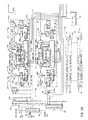
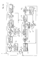
- the booster 16 includes a plurality of communication paths such as channel paths 22-30 which provide for transmission of five channels of control or audio in parallel between the mobile unit M and the cell site 12.
- the booster 16 also includes a plurality of cell site to mobile communication paths 32-40 for transmitting five channels of control or audio between cell site 12 and the mobile M.
- Signals from the cell site 12 transmitted to the booster 16 and detected at antenna 18 pass through duplexer 50 and enter multi-coupler 52.
- the multi-coupler 52 provides RF amplification of low level signals.
- Output from the multi-coupler 52, on lines 52a-e, provides input to the communication paths 32-40 which, as discussed subsequently, are implemented as intermediate frequency transmission paths.
- Output from each of the paths 32-40 is amplified in RF power output amplifiers 54a-e.
- Amplified outputs from the amplifiers 54a-e are combined in a high power lossless combiner 56.
- separate antennas may be employed for each RF power amplifier, or a very high power linear amplifier using distortion cancelling techniques may be used with a single antenna.
- the output from the combiner 56, on a single line 56a, is coupled to a duplexer 58. Output from the duplexer 58 is then transmitted via the antenna 20 to the mobile M.
- Incoming signals received from the mobile unit M at the antenna 20 are coupled via the duplexer 58 to multi-coupler 60.
- Outputs from the multi-coupler 60 drive the intermediate frequency communication paths 22-30.
- Outputs from the paths 22-30 are combined in a five way combiner 62.
- the combined output from the five way combiner 62 is amplified in the linear amplifier 64.
- the output from the amplifier 64 provides an input to the duplexer 50.
- Output from the duplexer 50 is coupled via the directional antenna 18 to the cell site 12.
- the intermediate frequency communication paths 22-30 and 32-40 operate under control of a stored program control unit 66. Each of the paths 22-30 is identical. Similarly, each of the paths 32-40 is identical.
- the booster 16 provides for the use of individual channel filters, implemented as the intermediate frequency paths such as 22 or 32.
- the intermediate frequency paths 22-30 and 32-40 represent a subset of a total number of channels which would normally be available from the cell site 12 assuming that the mobile M would be in an area of good reception.
- the boosted control channel and voice channels may be transmitted between the booster 16 and the cell site 12 or between the booster 16 and the mobile M on the same frequencies as received (F1-F1 mode of operation) or on different frequencies (F1-F2 mode of operation). Frequency translation alleviates problems of signal cancellation on the periphery of the boosted area. This also permits the use of greater gain through the transmission paths 22-30 or 32-40.
- Operation of the booster 16 is based on the fact that the closer the mobile M is to the cellular booster 16 the more likely that it will be in the vicinity where direct coverage from the cell site 12 is marginal. Mobiles near the cellular booster 16 will have higher signal levels then mobiles in other places. This provides a means for determining which channels require repeating. Accordingly, coverage in the problem area is achieved by placing the available individual communication paths on those channels associated with the strongest of the active mobile signals.
- the cellular booster 16 scans all of the available donor cell channels in a brief period of time, less then a couple of seconds. For each scanned channel a running average is updated of the signals that exceed a minimum threshold. An average of I out J readings exceeding this threshold provides a readily implementable test which can be used to determine which signals should be repeated and which signals should be dropped.
- Mobiles that are driving into the area served by the booster 16 are monitored for several scans thereof to determine the signal level trend before boosting or retransmission of the mobile is attempted. As a result, erroneous boosting of channels due to momentarily strong mobile signals can be minimized.
- Subscribers approaching the coverage area of the booster 16 are generally picked up within five or ten seconds.
- the subscribers are dropped upon leaving the area due to either falling below a predetermined minimum threshold or being voted out by other stronger mobile system signals closer to the booster 16.
- a specific transmission path can be provided for the control channel of the cell site 12 to allow mobile call originations or terminations to be completed for those mobiles which are not currently active but which are in the vicinity of the booster 16.
- the transmission path for the control channel may be purposely offset to provide F1-F2 repeater operation.
- an “action” threshold level is provided to allow quick response in setting up a boosted transmission path for a new call. This "action" threshold level is generally higher than the minimum threshold level. A signal exceeding this level is flagged for immediate action at the end of a scan.
- the mobile will transmit on the channel assigned by the cell site 12 for a maximum of five seconds without the presence of a correct supervisory audio tone being detected by the booster 16.
- a boosted transmission path will be placed on that channel within a couple of seconds. If the signal is below that threshold but above the minimum threshold, a boosted transmission path will be assigned within five seconds or so.
- Weaker mobile signals that approach the minimum threshold will generally be in an area where some coverage is provided directly from the cell site 12. This provides adequate time for the booster 16 to average the readings and determine that a new channel is to be boosted.
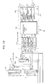
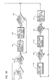
- the communication path 22 is identical to paths 24-30 and paths 32-40. A description of the structure of path 22 is thus applicable to the paths 24-40.
- the path 22 includes input circuitry 70 and output circuitry 72.
- Input to the path 22 on a line 60a from the multiplexer 60 is a modulated signal in the 824 to 849 MHz range.
- the circuitry 70 converts that high frequency input on the line 60a to an intermediate frequency in a range on the order of 70 MHz for the purpose of controllably amplifying that signal for retransmission to the cell site 12.
- the circuitry 70 includes a mixer 70a.
- the mixer 70a can be a model SRA-1 marketed by Mini-Circuits Corp., or similar.
- the mixer 70a is controlled by a local voltage controlled oscillator 70b which provides a local oscillator input frequency for conversion of the input signal on the line 60a to the 70 MHz intermediate frequency.
- Output from the voltage controlled oscillator 70b also provides an input to divide by N circuitry 70c.
- the divide by N circuitry 70c is a frequency divider element which provides selected signals from the voltage controlled oscillator 70b to a frequency synthesizer 70d.
- the frequency synthesizer 70d can be implemented employing a MC14159 prescaler circuit in addition to other commonly used components such as voltage-controlled RF oscillators and stable reference oscillator sources.
- Output from the mixer circuitry 70 on a line 70e at the 70 MHz intermediate frequency provides electrical input to the intermediate frequency circuitry 74.
- the intermediate frequency circuitry 74 includes a gain-programmable intermediate frequency amplifier 74a.
- the amplifier 74a is programmable and its gain is set by microprocessor 74b.
- Microprocessor 74b also provides control input signals to the synthesizer 70d.
- Output from the programmable amplifier 74a is filtered in a 30 KHz bandwidth intermediate frequency filter 74c.
- the filter 74c provides adjacent channel rejection to signals 30 KHz or more away from the signal being repeated on the path 22.
- Output from the intermediate frequency filter 74c drives programmable amplifier 74d which is identical to the amplifier 74a.
- Amplifiers 74a and 74d can be Avantek 0885 or similar.
- the 30 KHz bandwidth intermediate frequency filter 74c can be composed of several individual two-pole crystal filters such as NDK 70N20C.
- Programmable amplifier 74d also receives input from an injection oscillator 74e.
- the oscillator 74e is a stable, crystal oscillator at the 70 MHz intermediate frequency.
- the oscillator 74e is used to inject an intermediate frequency signal into the programmable amplifier 74d when data is to be transmitted.
- the injection oscillator 74e operates under the control of the 63C05 microprocessor 74b.
- Signal strength amplifier 74f is an IF amplifier which operates at a frequency lower than that of the filter 74c. This amplifier is a received signal strength indicator (RSSI). It provides both discriminator audio output and an analog DC signal output which is proportional to the radio frequency signal level input. The signal strength amplifier 74f provides its outputs to the microprocessor 74b and contains its own local oscillator for conversion to the lower intermediate frequency.
- RSSI received signal strength indicator
- Intermediate frequency circuitry 72 includes a driver amplifier 72a.
- the amplifier 72a is a radio frequency amplifier used to provide sufficient signal level in the 824 to 849 MHz range to drive the linear output amplifier 64.
- a reference oscillator 76 provides input to the two frequency synthesizers 70d and 72d.
- any offset in the input carrier frequency on the line 60a of the signal to be boosted will be translated to the output frequency on the line 22a.
- the transceiver in the mobile or the transceiver in the cell site 12 controls the basic accuracy of the boosted signal in this configuration.
- the stored program control unit 66 includes an 8031 Intel microprocessor 66a.
- the processor 66a provides overall control for the booster 16. It communicates with the other circuitry in the booster 16 via a serial board 66b.
- the control unit 66 also includes a 10 kilobit data demodulator and a 6 kHZ supervisory audio tone (SAT) demodulator 66c.
- the demodulator 66c includes circuitry for decoding the 10 kilobite data stream which is utilized in the cellular system and for measuring which of the SAT three 6 kHZ frequencies are being transponded by the cellular mobile unit such as the mobile unit M.
- the control unit 66 also includes a filter modulator unit 66d.
- the unit 66d includes a low-pass filter and gate for sending 10KB/Sec data in the standard cellular format for frequency modulation of one of the paths in the booster 16.
- the control unit 66 also includes a power amplifier control unit 66e.
- the power amplifier control unit 66e has outputs for enabling or disenabling the RF power amplifiers such as the amplifiers 54a-e and the amplifier 64.
- the power amplifier control unit 66e also includes an input for sensing the temperature of each of the power amplifiers.
- the control unit 66 also includes an output power sampling unit 66f.
- the sampling unit 66f converts analog DC voltage which is proportional to the radio frequency output power of the amplifiers 54a-e and 64 to a digital word for processing by the control unit 66.
- the control unit 66 also includes a random access memory module 66g, an electrically erasable read only memory module 66h for nonvolatile storage of alterable information and an electrically programmable read only memory module 66i for program storage.
- An RS232 interface 66j is also provided for connection of a computer terminal or a test cellular mobile to the booster 16.
- the control unit 66 is utilized for maintaining signal level history for processing purposes as well as for controlling the frequency synthesizers, such as the synthesizers 70d and 72d. It is also used for setting the signal gain through each path as well as for measuring the received signal levels on each channel and for carrying out diagnostic and parameter setting functions.
- the cellular booster scans all of the donor cell channels in less than a couple of seconds. For each channel, it updates a running average of the signals that exceed the minimum threshold (an average of I out of J readings exceeding this threshold).
- the minimum threshold an average of I out of J readings exceeding this threshold.
- a transmission path is provided on the donor cell control channel to allow mobile call originations or call terminations to be completed for those mobiles that are in the poor coverage area but are not currently active.
- an "Action" threshold level is provided to allow quick response in setting up a transmission path for the new call. This "Action" threshold level is generally higher than the minimum threshold level. A signal exceeding this level is flagged for immediate action at the end of a scan.
- the mobile will transmit on the channel assigned by the donor cell site for a maximum of 5 seconds without the presence of the correct SAT before it disconnects the call. If the mobile signal exceeds the "Action" threshold, a transmission path will be placed on that channel within a couple of seconds. If the signal is below the threshold but well above the minimum threshold, then a repeater channel will be assigned within 5 seconds or so. Weaker mobile signals that approach the minimum threshold will generally be in an area where some coverage is provided directly from the cell site, thus allowing adequate time for the cellular booster to average the readings and determine that the new channel is to be boosted.
- a parallel approach to assure that all new call attempts through the boosted control channel are connected through a boosted voice channel includes decoding the new channel assignments that are contained in the cell site control channel data stream.
- the signal level of the mobile responding to the channel assignment can thus be measured immediately, and its signal level compared with the current "running average" signal level set of other boosted channels.
- a transmission path can thus be assigned immediately unless all paths are already assigned to other stronger signals.
- This approach is based on the premise that enough transmission paths will be available to handle the expected peak subscriber load of the problem coverage area.
- a grade of service factor will be present where peak loads with a lot of nearby mobiles may result in a denial of service to other mobiles which may need boosting.
- the cellular operator may accept this level of service.
- the level of service may be improved by adding additional transmission paths in much the same manner as establishing a grade of service with a standard cell site.
- a degree of hysteris is provided to prevent mobiles from needlessly being dropped as they are moving about in the problem area.
- a new criteria (I out of K rather than I out of J readings, where K is larger than J) is applied to those channels currently being boosted. Thus, a larger number of readings below the minimum threshold is allowed before the call is dropped.
- the flow diagram of Figures 3A-3D also illustrates a method for placing the mobiles on voice channels that are different than those assigned by the donor cell. This represents an F1-F2 mode of operation. This accomplished by sending the mobile a "handoff" message to place the mobile on a new unused voice channel. The information transmitted from the cell site is thus translated to the new channel on which the mobile has been placed. Transmissions from the mobile are translated back to the correct channel for reception by the cell site. If the mobile is in an area where the signal from the cell site is about the same level or is stronger than the signal from the booster, then the handoff will not be accomplished. This is desirable since signals from the cell site are strong enough to allow continued direct communication.
- a mobile that is communicating with a cell site through the booster (operating in the F1-F2 mode) will be handed back to the original donor cell channel assignment as it drives out of the range of the booster's coverage area. This will allow the cell system to continue processing the call via normal handoffs if the mobile requires further attention.
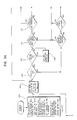
- the booster 16 is first manually initialized in a step 100. Initialization includes specifying the total number of channels M available at the cell site 12. Next the number of transmission paths N, available in the booster 16, is specified. For the exemplary embodiment a total of 5 transmission paths are available each way. Next a minimum threshold level of the incoming signal from either the cell site 12 or the mobile M is specified. This threshold can be specified in decibels with respect to milliwatts. Signals above this minimum level are candidates for boosting or repeating. Signals below this level are disregarded.
- the “action” level threshold is higher than the minimum level threshold and is used to differentiate those mobiles which are quite close to the booster 16 and should be given priority service from those which are further away and might be receiving adequate service directly from the cell site 12.
- the number of measurements J for each channel is specified for purposes of maintaining a running history of sensed incoming signals.
- a minimum number of acceptable measurements I is also specified. In operation there must be a minimum of at least I signals measured out of a total of J signals measured which are above the previously set minimum threshold in order to initiate signal boosting.
- K A number of acceptable measurements, K, is also specified at initialization.
- the number K is used for the purpose of determining whether or not to continue to enhance signals to and from a mobile unit M.
- the value of K is the same as or greater than the value of J.
- the booster in a step 102 initiates scanning by examining the first channel to determine if there are any mobiles active thereon. If an incoming signal from a mobile unit, such as the unit M, is detected, in a step 104, the booster 16 determines whether or not the correct supervisory audio tone (SAT) has been received.
- SAT supervisory audio tone
- the booster 16 determines whether or not the channel currently being scanned is actively being boosted. If so, a five second SAT timer is initiated in a step 108.
- the SAT timer provides a five second delay which upon expiration, if this repeater channel is active, may permit the channel to be dropped. This would correspond to a signal which was properly being boosted initially and which at some point ceased to have the SAT associated with the cell site 12.
- a step 110 the incoming signal is compared to the preset minimum threshold to determine whether or not that threshold is exceeded. If that threshold is not exceeded then no boosting of that signal is attempted. If the signal does exceed the minimum prespecified threshold then boosting of that signal may be attempted.
- the incoming signal is compared to the previously set "action" threshold level to determine whether or not the mobile unit M is exceedingly close to the booster 16. If the incoming signal exceeds the "action" level threshold in a step 114, the repeater checks to determine whether or not the incoming signal is already being boosted. If so, it goes on to check the next channel in a step 116.
- the last J readings for this channel are set to the current value which has just been read in the step 112.
- the signal becomes a very high probability candidate for being immediately repeated. This corresponds to the mobile unit M being quite close to the booster 16 and usually in a region wherein the cell site 12 provides inadequate service.
- the booster 16 determines whether or not this channel is currently being boosted. If not in a step 124 it determines whether or not the last I out of J readings associated with the present channel have been above the predetermined minimum threshold. If not, the signal is not a candidate for being boosted.
- the signal is a candidate for being boosted.
- the average value of the last I readings along with channel number is recorded in a step 126.
- the next channel is then tested in a similar fashion until all of the channels associated with the cell site 12 has been examined.
- the booster 16 determines whether or not the last I out of K readings exceeded the predetermined minimum threshold. If not, in a step 130 boosting of this signal ceases and the channel identification is removed from a table identifying those channels being boosted. If on the other hand in the step 128 the last I out of K readings for the signal are above the predetermined minimum threshold then the signal continues to be boosted and the booster goes on to the step 116.
- a parallel process wherein the signal level information can be reapidly determined is accomplished by continuously monitoring in a step 142 the control channel from the donor cell. Whenever a channel assignment is monitored from the donor cell, the signal level from the intended mobile is measured in a step 146. If in a step 148 the mobile response to the channel assignment exceeds the minimum selected threshold level, then the channel table is updated in a step 150 to immediately add this channel to the candidate list.
- the minimum threshold level can be the same as the "Action" level described earlier. It could also be a separately programmed level that either is provided by the operator or determined on a dynamic basis from the table of received signal levels that are being received by the active repeater channels. This operation is analogous to the steps 118 and 126 described earlier, and is used in conjuntion with these two steps to continuouly update the candidate channel list.
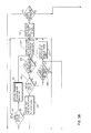
- the booster determines in a step 132 whether or not there are more candidates for boosting than there are available booster transmission paths. If not, the booster 16 tests in a step 134 to determine whether or not the list of potential signals to be boosted is the same as or different from the list of those currently being boosted. If not, all of the channels continue to be repeated and the booster 16 returns to the step 102.
- a subset of the candidates available for repeating is selected.
- the list of potential candidates for boosting is compared with the currently assigned repeater channels. If there is a difference noted in the step 134, then a process of adding and/or dropping channels will take place, as illustrated by figure 3C.
- the list of candidate channels is examined in a step 152 to first determine if any channels are to be dropped. This is necessary to release communication paths for assignment to new channels. If any are to be dropped, the first channel in the list to be dropped is selected in a step 153. Next, a determination is made in a step 154 to establish if this channel that is currently being repeated is a translated channel (F1-F2), or a same-frequency boosted channel (F1-F1). If it is not a translated (F1-F2) channel, then the channel repeater is immediately disabled in a step 164 to free up the channel equipment for a new call.
- F1-F2 translated channel
- F1-F1-F1-F1 a same-frequency boosted channel
- a hand-off message is first sent to the mobile in a step 156 to place the mobile back on the same channel as the donor cell (i.e., back to an F1-F1 mode).
- a test is made in a step 158 to determine whether the mobile acknowledges the hand-off message. If the mobile did not acknowledge the hand-off message, a retry counter is incremented in a step 160. The hand-off message is repeated if the retry count has not been exceeded in a step 162. Either acknowledgment of the hand-off message or exceeding the retry count will cause the repeater to be disabled for this channel. If the mobile does not acknowledge the hand-off message, then it is beyond the range of the booster.
- step 166 a check is made to determine if any other channels are to be dropped. If more channels remain, the retry counter is reset and the steps 156 through 164 are repeated as before to release transmission paths no longer required for signal boosting.
- step 166 If there are no further channels to be dropped as determined in the step 166, or if there were no channels initially to be dropped as determined in the step 152, then a test is made in a step 170 to determine whether any channels are to be added. If not, then the booster returns to the step 102.
- the parallel monitoring of new channel assignments in steps 142 through 150 continues to determine and update new candidates for channel assignment.
- step 170 If in the step 170 a determination is made that new channels are to be added, then the first candidate channel that is to be added is selected in a step 172. Next, a determination is made in a step 174 to establish if this channel is to be a translated channel (F1-F2), or a same-frequency boosted channel (F1-F1). If it is not to be a translated (F1-F2) channel, then an available channel repeater, communication path, is immediately assigned to this channel in a step 180.
- F1-F2 translated channel
- F1-F1-F1-F1 a same-frequency boosted channel
- a hand-off message containing the new channel assignment is sent to the mobile on the original channel to which the mobile has been assigned by the donor cell, in a step 176. If the mobile confirms the hand-off message on the newly assigned channel, in a step 178, then the channel equipment associated with the call is enabled in the F1-F2 frequency translation mode, in a step 180.
- a retry counter is incremented in a step 184.
- the hand-off to the target mobile is then retransmitted. If the mobile fails to acknowledge the hand-off message after "N" retries as in a step 186, then the repeater equipment is not enabled for this candidate.
- the channel equipment is set up as previously described for steps 174 through 180 and 184 through 186. After all channel candidates have been processed, then the process returns to the step 102. Monitoring of new channel assignments in steps 142 through 150 continues in parallel with the updating and determination of new candidates for channel assignment.
- a corridor extension system can be implemented using a plurality of boosters of the type previously described.
- a series coupled arrangement of such boosters will provide highly directive coverage, cost effectively, along such a corridor.
- Figure 4 is an over-all diagram of a cell extender system 200. Frequencies are indicated on Figure 4 for a voice channel downlink and a voice channel uplink. A frequency indicated by a prime, "′" is off-set from an unprimed corresponding frequency by 45 MHz.
- the system 200 includes a plurality 202 of boosters 204-212 that extend the coverage of the cells by repeating the downlink signals from the cell site S to the mobile M and the uplink signals from the mobile M to the cell site S.
- the repeated signals are relayed from booster to booster using two sets of frequencies that are not part of the mobile frequency set that is in use.
- Logic in the booster based upon received signal levels determines whether the booster repeats the mobile frequencies or the booster frequencies.
- the mobile M will always use a single set of frequencies for voice or audio channel use when functioning through any of the boosters. This has the advantage that no hand-off is necessary in the mobile as it moves from the coverage of one booster to another booster. Hand-off is required when the mobile moves from the booster coverage area to the cell-site coverage area because the cell site S uses another set of frequencies for the voice channels.
- the cell site S dictates which voice channels the mobile is to operate on during the initial stages of the call setup.
- the booster that is processing a call setup to or from a mobile immediately sends a hand-off message to that mobile to place it on a channel in the f2 set.
- the booster closest to the donor site S then translates the mobile frequency back to the original channel in the f1 frequency set that was assigned by the cell site S.
- the hand-off step described above may be bypassed by incorporating the f2 frequency set in the channel assignment list at cell site S, while maintaining the f1 frequency set for actual transmission and reception of voice messages to the nearest booster in the corridor.
- a single set of frequencies (the f2 set) for mobile conversations in the booster within the chain in conjunction with the stored program logic contained within the boosters causes only the booster that has a usable signal from the mobile and is closet to the cell site S to communicate with the mobile on a channel in the f2 frequency set.
- the control channel requires two or more different frequencies because the down-link control channel must be repeated at each booster to provide continuous coverage throughout the booster corridor area. If omnidirectional antennas are used for booster transmissions to and from the mobile, then a third set of frequencies may be necessary to preclude interference between even or odd-numbered boosters along the corridor.
- control channel signal from cell site S can thus be repeated on alternate channels at each booster in the chain.
- the booster logic for relaying the control channel uplink signal is similar to the voice channel logic.
- the booster will relay the mobile uplink signal if it is receiving a usable signal. If not, then the uplink signal from the down-stream booster if it is present, will be retransmitted. Otherwise, the control channel uplink booster is off.
- the frequency allocation for the system 200 requires four sets of frequencies and in some cases one extra control channel frequency, includes the frequency set for the cell site. There is a one-for-one relationship between the frequencies in one set and the frequencies in another set.
- the table below shows an example for a four booster extender system.
- Table II illustrates the operation of the system 200 when calls are originated while the mobile M is in the coverage area of the system 200.
- the mobile M remains on its initially assigned voice frequency as it moves from one coverage area to another such as from booster 206 to booster 208.
- Hand-off of the mobile M as it moves from a cell-site coverage area into the system 200 coverage area or as it moves out of the system 200 coverage area will require varying responses.
- Three approaches that may be used individually or in combination are:
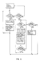
- FIG. 5 is a flow diagram for each of the Boosters 204-212 that determines which uplink signal is to be transmitted on the Booster control-channel uplink: the mobile, the next Booster, or nothing.
- the control channel Booster always transmits the received downlink on the mobile control channel frequency.
- the voice channel assignment may need to be modified to the frequencies in the Booster to the mobile set. If this is the case, the control channel logic in the Booster closest to the cell site S must modify the channel assignment because it is the only Booster that can determine which voice channels in the Booster set assigned to the system 200 are free for assignment. If all voice channels in the Booster set are busy, it must generate a busy signal to send to the mobile M.
- FIG. 6 is a flow diagram for each of the Boosters 204-212 that determines which voice channel signals to repeat: the mobile, the next Booster, or nothing. If the Booster is receiving a usable mobile uplink voice channel signal, it will always repeat the mobile uplink and transmit the voice channel on the mobile downlink frequency. In the case of an uplink signal but no downlink signal, only the uplink is repeated.
- a scanning receiver is used to monitor the mobile channels to detect a mobile that has moved into its coverage area after the mobile voice channel was assigned by the cell site S control channel.
- Voice channel logic will force the mobile M to be repeated by the Booster that is nearest the cell site S if it is receiving a usable uplink signal, even though the next Booster may be receiving a stronger signal.
Landscapes
- Engineering & Computer Science (AREA)
- Computer Networks & Wireless Communication (AREA)
- Signal Processing (AREA)
- Mobile Radio Communication Systems (AREA)
- Radio Relay Systems (AREA)
- Bipolar Transistors (AREA)
- Diaphragms For Electromechanical Transducers (AREA)
- Saccharide Compounds (AREA)
- Amplifiers (AREA)
- Nitrogen And Oxygen Or Sulfur-Condensed Heterocyclic Ring Systems (AREA)
- Solid-Sorbent Or Filter-Aiding Compositions (AREA)
- Medicines That Contain Protein Lipid Enzymes And Other Medicines (AREA)
Priority Applications (1)
| Application Number | Priority Date | Filing Date | Title |
|---|---|---|---|
| AT88112568T ATE96954T1 (de) | 1987-08-03 | 1988-08-02 | Booster-verstaerker. |
Applications Claiming Priority (2)
| Application Number | Priority Date | Filing Date | Title |
|---|---|---|---|
| US07/081,120 US4941200A (en) | 1987-08-03 | 1987-08-03 | Booster |
| US81120 | 1987-08-03 |
Publications (3)
| Publication Number | Publication Date |
|---|---|
| EP0302455A2 EP0302455A2 (en) | 1989-02-08 |
| EP0302455A3 EP0302455A3 (en) | 1990-09-05 |
| EP0302455B1 true EP0302455B1 (en) | 1993-11-03 |
Family
ID=22162220
Family Applications (1)
| Application Number | Title | Priority Date | Filing Date |
|---|---|---|---|
| EP88112568A Expired - Lifetime EP0302455B1 (en) | 1987-08-03 | 1988-08-02 | Booster |
Country Status (8)
| Country | Link |
|---|---|
| US (2) | US4941200A (ja) |
| EP (1) | EP0302455B1 (ja) |
| JP (1) | JP2919839B2 (ja) |
| AT (1) | ATE96954T1 (ja) |
| DE (1) | DE3885369T2 (ja) |
| ES (1) | ES2047510T3 (ja) |
| FI (1) | FI88658C (ja) |
| HK (1) | HK1004310A1 (ja) |
Families Citing this family (108)
| Publication number | Priority date | Publication date | Assignee | Title |
|---|---|---|---|---|
| US5152002A (en) * | 1987-08-03 | 1992-09-29 | Orion Industries, Inc. | System and method for extending cell site coverage |
| US4911115A (en) * | 1987-09-15 | 1990-03-27 | Performance Industries, Inc. | Slide exhaust control valve for fuel injected two-stroke cycle engines and process for using same |
| US4909193A (en) * | 1987-09-15 | 1990-03-20 | Performance Industries, Inc. | Exhaust control valve for fuel injected two-stroke cycle engines and process for using same |
| US4924819A (en) * | 1987-09-15 | 1990-05-15 | Performance Industries, Inc. | Rotary exhaust control valve for two-stroke cycle engines and process for using the same |
| CA2019814A1 (en) * | 1989-07-07 | 1991-01-07 | Linwood C. Watkins, Jr. | Dual donor booster system |
| GB2239996B (en) * | 1990-01-12 | 1994-08-17 | Technophone Ltd | Booster for a portable radio telephone |
| US5187806A (en) * | 1990-02-16 | 1993-02-16 | Johnson Edward R | Apparatus and method for expanding cellular system capacity |
| US5179720A (en) * | 1990-02-23 | 1993-01-12 | Motorola, Inc. | Method and apparatus for extended coverage of a trunked radio communications system |
| CA2041705A1 (en) * | 1990-07-25 | 1992-01-26 | Jesse Eugene Russell | Method and apparatus for providing wireless communications between remote locations |
| US5218715A (en) * | 1991-01-15 | 1993-06-08 | Orion Industries, Inc. | Multi-donor booster operation and system |
| US5265150A (en) * | 1991-01-30 | 1993-11-23 | At&T Bell Laboratories | Automatically configuring wireless PBX system |
| US5434798A (en) * | 1991-05-23 | 1995-07-18 | Telefonaktiebolaget L M Ericcson | Reconfiguration in a cellular communications network |
| WO1992022161A1 (en) * | 1991-05-29 | 1992-12-10 | Communications Satellite Corporation | Fully meshed cdma network for personal communications terminals |
| CA2058737C (en) * | 1992-01-03 | 1997-03-18 | Andrew S. Beasley | Rf repeater arrangement with improved frequency reuse for wireless telephones |
| US5548803A (en) * | 1992-03-31 | 1996-08-20 | Orion Industries, Inc. | Dual-mode booster system |
| EP0568142A2 (en) * | 1992-04-28 | 1993-11-03 | Koninklijke Philips Electronics N.V. | Improved transmitter network with a single transmitter frequency |
| US5377255A (en) * | 1992-07-14 | 1994-12-27 | Pcs Microcell International Inc. | RF repeaters for time division duplex cordless telephone systems |
| US5444862A (en) * | 1992-09-30 | 1995-08-22 | Fujitsu Limited | Circuit for stopping data transmission responding to low level and rapid fall of received electric field |
| US5561845A (en) * | 1992-10-02 | 1996-10-01 | Orion Industries, Inc. | Apparatus and method for preserving coverage in an overlapping coverage area |
| KR960000147B1 (ko) * | 1992-11-05 | 1996-01-03 | 삼성전자주식회사 | 셀룰라 무선전화시스템의 송신전력 제어방법 |
| US5542119A (en) * | 1993-02-26 | 1996-07-30 | Motorola, Inc. | Method for selecting a highest quality signal for retransmission by base sites in a simulcast communication system |
| FI108382B (fi) * | 1993-05-27 | 2002-01-15 | Sonera Oyj | Laitteisto ja menetelmõ tiedon siirtõmiseksi |
| US5408681A (en) * | 1993-08-16 | 1995-04-18 | The United States Of America As Represented By The Secretary Of The Navy | Automatic repeater station for signal transmissions |
| JPH0766775A (ja) * | 1993-08-30 | 1995-03-10 | Kokusai Electric Co Ltd | 中継増幅装置 |
| US5530409A (en) * | 1993-10-21 | 1996-06-25 | At&T Corp. | Signal processing allocator |
| US5544222A (en) * | 1993-11-12 | 1996-08-06 | Pacific Communication Sciences, Inc. | Cellular digtial packet data mobile data base station |
| US5469471A (en) * | 1994-02-01 | 1995-11-21 | Qualcomm Incorporated | Method and apparatus for providing a communication link quality indication |
| SE502811C2 (sv) * | 1994-05-11 | 1996-01-22 | Allgon Ab | Repeater |
| US5818385A (en) * | 1994-06-10 | 1998-10-06 | Bartholomew; Darin E. | Antenna system and method |
| US5787344A (en) * | 1994-06-28 | 1998-07-28 | Scheinert; Stefan | Arrangements of base transceiver stations of an area-covering network |
| DE69533934T2 (de) * | 1994-11-04 | 2005-12-01 | Andrew Corp., Orland Park | Basisstation für zellulares Telekommunikationssystem, Verfahren zur Keulenabwärtsneigung und Antennensteuerungsanordnung |
| FR2727590B1 (fr) * | 1994-11-24 | 1996-12-27 | Alcatel Espace | Charge utile de satellite a canaux transparents integres |
| GB2299732B (en) * | 1995-04-06 | 1999-08-11 | Nokia Mobile Phones Ltd | A Wireless Base Station |
| US6370135B1 (en) | 1995-06-07 | 2002-04-09 | Cirrus Logic, Inc. | Continuous CDPD base station and method of facilitating efficient data transfer |
| US6334062B1 (en) | 1995-06-07 | 2001-12-25 | Cirrus Logic, Inc. | Portable communications and data terminal operating to optimize receipt of both incoming CDPD and AMPS messages |
| US5697052A (en) * | 1995-07-05 | 1997-12-09 | Treatch; James E. | Cellular specialized mobile radio system |
| NL1000875C2 (nl) * | 1995-07-24 | 1997-01-28 | Nederland Ptt | Telecommunicatiesystemen, alsmede basisstation alsmede repeaterstation, alsmede werkwijzen. |
| US5890055A (en) * | 1995-07-28 | 1999-03-30 | Lucent Technologies Inc. | Method and system for connecting cells and microcells in a wireless communications network |
| US5737706A (en) * | 1995-08-03 | 1998-04-07 | Bell Atlantic Network Services, Inc. | Power system supporting CDPD operation |
| FI955179A0 (fi) | 1995-10-30 | 1995-10-30 | Finland Telecom Oy | Anordning och foerfarande foer dataoeverfoering |
| US5774789A (en) * | 1995-12-14 | 1998-06-30 | Allen Telecom Inc. | RF communication signal distribution system and method |
| US5850592A (en) | 1996-01-11 | 1998-12-15 | Gte Internetworking Incorporated | Method for self-organizing mobile wireless station network |
| DE29601436U1 (de) * | 1996-01-29 | 1996-04-18 | Impex Ges Fuer Elektronische A | Funkgesteuerte Signalmelde- und -empfangsanlage |
| DE19611342A1 (de) * | 1996-03-22 | 1997-09-25 | Mikom Gmbh | Repeater-Anordnung |
| US6088592A (en) * | 1996-03-25 | 2000-07-11 | Airnet Communications Corporation | Wireless system plan using in band-translators with diversity backhaul to enable efficient depolyment of high capacity base transceiver systems |
| US5883884A (en) * | 1996-04-22 | 1999-03-16 | Roger F. Atkinson | Wireless digital communication system having hierarchical wireless repeaters with autonomous hand-off |
| FI105511B (fi) | 1996-10-29 | 2000-08-31 | Nokia Networks Oy | Menetelmä usean signaalin yhdistämiseksi ja tukiasema |
| US6016313A (en) * | 1996-11-07 | 2000-01-18 | Wavtrace, Inc. | System and method for broadband millimeter wave data communication |
| US5978650A (en) | 1997-01-21 | 1999-11-02 | Adc Telecommunications, Inc. | System and method for transmitting data |
| US5937332A (en) * | 1997-03-21 | 1999-08-10 | Ericsson, Inc. | Satellite telecommunications repeaters and retransmission methods |
| SE521614C2 (sv) * | 1997-08-28 | 2003-11-18 | Ericsson Telefon Ab L M | Metod och apparat för radioeffektallokering och fördelning |
| US6104936A (en) * | 1997-09-30 | 2000-08-15 | Telefonaktiebolaget Lm Ericsson | Method and apparatus for optimizing antenna tilt |
| US6269241B1 (en) * | 1997-11-26 | 2001-07-31 | Aerocomm, Inc. | Ultra-Q filter |
| US6487187B1 (en) * | 1997-11-26 | 2002-11-26 | Airnet Communications Corporation | Random access control channel gain control and time slot recovery for remote in-band translator in time division multiple access wireless system |
| JP3037927B2 (ja) * | 1998-03-30 | 2000-05-08 | インターナショナル・ビジネス・マシーンズ・コーポレイション | 転送方法及び移動無線送受信機 |
| US6400968B1 (en) * | 1998-05-04 | 2002-06-04 | Conexant Systems, Inc. | System and method for extending the range of a base unit |
| FI106674B (fi) * | 1998-05-14 | 2001-03-15 | Nokia Networks Oy | Menetelmä solukkoradiojärjestelmän toiminnan valvomiseksi |
| US6650630B1 (en) * | 1999-06-25 | 2003-11-18 | Telefonaktiebolaget Lm Ericsson (Publ) | Resource management and traffic control in time-division-duplex communication systems |
| US6239744B1 (en) | 1999-06-30 | 2001-05-29 | Radio Frequency Systems, Inc. | Remote tilt antenna system |
| US7577398B2 (en) | 2000-01-14 | 2009-08-18 | Andrew Llc | Repeaters for wireless communication systems |
| IL137078A (en) * | 1999-07-20 | 2005-05-17 | Andrew Corp | Side-to-side repeater and adaptive cancellation for repeater |
| DE19938862C1 (de) | 1999-08-17 | 2001-03-15 | Kathrein Werke Kg | Hochfrequenz-Phasenschieberbaugruppe |
| US20010031623A1 (en) * | 2000-03-03 | 2001-10-18 | Lee Masoian | Channel booster amplifier |
| US7142619B2 (en) * | 2000-04-26 | 2006-11-28 | Symmetricom, Inc. | Long subscriber loops using automatic gain control mid-span extender unit |
| ATE370558T1 (de) * | 2000-06-05 | 2007-09-15 | Sony Deutschland Gmbh | Drahtloses innenraumsystem mit aktivem reflektor |
| US6973053B1 (en) | 2000-09-12 | 2005-12-06 | Bbnt Solutions Llc | Using direct cluster member to cluster member links to improve performance in mobile communication systems |
| US6804501B1 (en) * | 2000-09-25 | 2004-10-12 | Prairiecomm, Inc. | Receiver having gain control and narrowband interference detection |
| US7088953B2 (en) | 2000-10-18 | 2006-08-08 | Spotwave Wireless Canada Inc. | Coverage area signature in an on-frequency repeater |
| CA2323881A1 (en) * | 2000-10-18 | 2002-04-18 | Dps Wireless Inc. | Adaptive personal repeater |
| DE10104564C1 (de) * | 2001-02-01 | 2002-09-19 | Kathrein Werke Kg | Steuerungsvorrichtung zum Einstellen eines unterschiedlichen Absenkwinkels insbesondere von zu einer Basisstation gehörenden Mobilfunkantennen sowie eine zugehörige Antenne und Verfahren zur Veränderung eines Absenkwinkels |
| KR100375318B1 (ko) * | 2001-03-02 | 2003-03-10 | (주)비엔씨모바일 | 주파수 변환 방식을 이용한 인-빌딩용 이동통신 중계 시스템 |
| US7133697B2 (en) * | 2001-05-14 | 2006-11-07 | Andrew Corporation | Translation unit for wireless communications system |
| US7103312B2 (en) * | 2001-09-20 | 2006-09-05 | Andrew Corporation | Method and apparatus for band-to-band translation in a wireless communication system |
| US7120456B1 (en) | 2001-11-07 | 2006-10-10 | Bbn Technologies Corp. | Wireless terminals with multiple transceivers |
| GB0200237D0 (en) * | 2002-01-07 | 2002-02-20 | Imec Inter Uni Micro Electr | Wireless cellular network architecture |
| US20040166802A1 (en) * | 2003-02-26 | 2004-08-26 | Ems Technologies, Inc. | Cellular signal enhancer |
| US6993287B2 (en) | 2003-03-04 | 2006-01-31 | Four Bars Clarity, Llc | Repeater system for strong signal environments |
| US7555261B2 (en) | 2003-03-04 | 2009-06-30 | O'neill Frank P | Repeater system for strong signal environments |
| US7558528B2 (en) * | 2003-07-31 | 2009-07-07 | Microsoft Corporation | Wireless local area network translating bi-directional packet repeater |
| IL161869A (en) | 2004-05-06 | 2014-05-28 | Serconet Ltd | A system and method for carrying a signal originating is wired using wires |
| CA2568422C (en) * | 2004-05-26 | 2013-07-23 | Wireless Extenders, Inc. | Wireless repeater implementing low-level oscillation detection and protection for a duplex communication system |
| CN1985528B (zh) * | 2004-06-03 | 2010-06-09 | 高通股份有限公司 | 具有低成本高性能本振架构的变频中继器 |
| WO2006043592A1 (ja) * | 2004-10-20 | 2006-04-27 | Matsushita Electric Industrial Co., Ltd. | ブースタ |
| JP4577792B2 (ja) * | 2005-03-23 | 2010-11-10 | パイオニア株式会社 | 伝送システム、送信側伝送器、伝送方法、及びコンピュータプログラム |
| US8477731B2 (en) * | 2005-07-25 | 2013-07-02 | Qualcomm Incorporated | Method and apparatus for locating a wireless local area network in a wide area network |
| JP4603462B2 (ja) * | 2005-10-26 | 2010-12-22 | 日本無線株式会社 | 中継装置 |
| JP4603464B2 (ja) * | 2005-10-28 | 2010-12-22 | 日本無線株式会社 | 中継装置および受信装置 |
| KR100943601B1 (ko) * | 2005-12-27 | 2010-02-24 | 삼성전자주식회사 | 멀티 홉 릴레이 방식을 사용하는 통신 시스템에서 중계국선택 방법 및 시스템 |
| US7813451B2 (en) | 2006-01-11 | 2010-10-12 | Mobileaccess Networks Ltd. | Apparatus and method for frequency shifting of a wireless signal and systems using frequency shifting |
| US20070232228A1 (en) * | 2006-04-04 | 2007-10-04 | Mckay David L Sr | Wireless repeater with universal server base unit and modular donor antenna options |
| US20090117859A1 (en) * | 2006-04-07 | 2009-05-07 | Belair Networks Inc. | System and method for frequency offsetting of information communicated in mimo based wireless networks |
| WO2008044554A1 (en) * | 2006-10-03 | 2008-04-17 | Panasonic Corporation | Relay station in mobile communication system and relay transmission channel setting method |
| EP2203799A4 (en) | 2007-10-22 | 2017-05-17 | Mobileaccess Networks Ltd. | Communication system using low bandwidth wires |
| US8175649B2 (en) | 2008-06-20 | 2012-05-08 | Corning Mobileaccess Ltd | Method and system for real time control of an active antenna over a distributed antenna system |
| US8750786B2 (en) | 2007-12-21 | 2014-06-10 | Telefonaktiebolaget Lm Ericsson (Publ) | Forwarding node in a wireless communication system |
| EP2399141A4 (en) | 2009-02-08 | 2012-08-01 | Corning Mobileaccess Ltd | COMMUNICATION SYSTEM WITH CABLE-TRANSMITTED ETHERNET SIGNALS |
| JP2010226655A (ja) * | 2009-03-25 | 2010-10-07 | Fujitsu Ltd | 中継方法及び中継装置 |
| JP5433404B2 (ja) * | 2009-12-25 | 2014-03-05 | 株式会社東芝 | 無線レピータ装置 |
| US10270152B2 (en) | 2010-03-31 | 2019-04-23 | Commscope Technologies Llc | Broadband transceiver and distributed antenna system utilizing same |
| US8346160B2 (en) | 2010-05-12 | 2013-01-01 | Andrew Llc | System and method for detecting and measuring uplink traffic in signal repeating systems |
| WO2013142662A2 (en) | 2012-03-23 | 2013-09-26 | Corning Mobile Access Ltd. | Radio-frequency integrated circuit (rfic) chip(s) for providing distributed antenna system functionalities, and related components, systems, and methods |
| IL222786A (en) | 2012-11-01 | 2016-09-29 | Elta Systems Ltd | Enable Boost to Downlink channels on a cellular communication system |
| WO2014188413A1 (en) | 2013-05-23 | 2014-11-27 | Elta Systems Ltd. | Add-on apparatus for synchronization of frequency diversity communications and methods useful in conjunction therewith |
| SG11201509236UA (en) | 2013-05-23 | 2015-12-30 | Elta Systems Ltd | Add-on apparatus for channel compensation of frequency diversity communications and methods useful in conjunction therewith |
| SG11201509237YA (en) | 2013-05-23 | 2015-12-30 | Elta Systems Ltd | Receiver, system and method for frequency diversity communications using beacon and methods useful in conjunction therewith |
| US9184960B1 (en) | 2014-09-25 | 2015-11-10 | Corning Optical Communications Wireless Ltd | Frequency shifting a communications signal(s) in a multi-frequency distributed antenna system (DAS) to avoid or reduce frequency interference |
| US10322048B2 (en) | 2017-01-31 | 2019-06-18 | NextHealth, LLC | Systems and methods for powered wheelchair personal transfer |
| IL256681B (en) | 2017-12-31 | 2021-06-30 | Elta Systems Ltd | Partial repeater device for uplink transmission–system, method and computer software product |
Family Cites Families (32)
| Publication number | Priority date | Publication date | Assignee | Title |
|---|---|---|---|---|
| US3045185A (en) * | 1958-05-19 | 1962-07-17 | Rca Corp | Repeater station having diversity reception and full hot standby means |
| US3028489A (en) * | 1959-12-28 | 1962-04-03 | Bell Telephone Labor Inc | Broadband radio relay system in which signals from adjacent repeaters are compared to control gain of each repeater |
| US3095538A (en) * | 1960-10-28 | 1963-06-25 | Silberstein Richard | Satellite relay station using antenna diversity selection |
| US3328698A (en) * | 1963-06-28 | 1967-06-27 | Itt | Selector for choosing the strongest signal including means for inhibiting all signals below a selected level |
| US3283249A (en) * | 1963-12-23 | 1966-11-01 | Bell Telephone Labor Inc | Broadband radio repeater having parallel channels |
| US3411088A (en) * | 1965-02-09 | 1968-11-12 | Bell Telephone Labor Inc | Automatic input power level adjustment apparatus for amplifier of a broadband repeater |
| US3450841A (en) * | 1965-08-02 | 1969-06-17 | Int Standard Electric Corp | Carrier frequency stabilization for carrier frequency systems with suppressed carrier waves |
| US3667043A (en) * | 1969-09-19 | 1972-05-30 | Telcom Inc | Constant gain bandwidth product communication satellite repeater |
| JPS5241082B2 (ja) * | 1973-03-28 | 1977-10-17 | ||
| US4041389A (en) * | 1975-07-09 | 1977-08-09 | Gte Automatic Electric Laboratories Incorporated | Nonfrequency-converting microwave radio repeater using a low power consumption amplifier |
| JPS5839423B2 (ja) * | 1976-08-30 | 1983-08-30 | 日本電信電話株式会社 | 無線回線制御方式 |
| JPS53148312A (en) * | 1977-05-31 | 1978-12-23 | Fujitsu Ltd | Demodulation system for auxiliary line in direct repeating radio unit |
| FR2425777A1 (fr) * | 1978-05-12 | 1979-12-07 | Dassault Electronique | Procede et appareil radio-electriques pour la collecte et le traitement d'informations provenant d'une multiplicite de postes |
| US4317218A (en) * | 1980-03-26 | 1982-02-23 | General Electric Company | Arrangement for remote control of repeater stations |
| US4317216A (en) * | 1980-05-09 | 1982-02-23 | Tx Rx Systems, Inc. | Bi-directional filter system for amplifying signals in separate frequency bands |
| ZA813229B (en) * | 1980-05-29 | 1983-01-26 | Philips Nv | Frequency division communication system wherein conventional transmitter-transceiver can be used as or repeater or local base station |
| US4475243A (en) * | 1982-12-21 | 1984-10-02 | Motorola, Inc. | Isolation method and apparatus for a same frequency repeater |
| US4475010A (en) * | 1983-05-05 | 1984-10-02 | At&T Bell Laboratories | High density cellular mobile radio communications |
| FR2556532B1 (fr) * | 1983-12-09 | 1986-10-24 | Trt Telecom Radio Electr | Procede de radiocommunication bidirectionnelle entre des stations fixes et des stations mobiles |
| GB2151883B (en) * | 1983-12-22 | 1987-10-21 | Motorola Inc | Queued community repeater communications system |
| JPS617736A (ja) * | 1984-06-22 | 1986-01-14 | Nec Corp | 無線中継方式 |
| US4613990A (en) * | 1984-06-25 | 1986-09-23 | At&T Bell Laboratories | Radiotelephone transmission power control |
| JPS623536A (ja) * | 1985-06-29 | 1987-01-09 | Oki Electric Ind Co Ltd | 移動体データ通信の良否判定装置 |
| US4696053A (en) * | 1985-07-03 | 1987-09-22 | Canadian Marconi Corporation | Antenna alignment system and method |
| FR2584884B1 (fr) * | 1985-07-09 | 1987-10-09 | Trt Telecom Radio Electr | Procede et dispositif de recherche de canal libre pour un systeme de radio mobile |
| US4849963A (en) * | 1985-10-15 | 1989-07-18 | Minori Kawano | Cellular radio telephone enhancement circuit |
| US4754495A (en) * | 1985-12-16 | 1988-06-28 | Minori Kawano | Cell enhancer for cellular radio telephone system having bandpass filter arrangement |
| US4726050A (en) * | 1986-02-18 | 1988-02-16 | Motorola, Inc. | Scanning receiver allocation method and apparatus for cellular radiotelephone systems |
| US4704734A (en) * | 1986-02-18 | 1987-11-03 | Motorola, Inc. | Method and apparatus for signal strength measurement and antenna selection in cellular radiotelephone systems |
| US4718108A (en) * | 1986-05-19 | 1988-01-05 | Motorola, Inc. | Improved multiple site communication system |
| US4646345A (en) * | 1986-06-09 | 1987-02-24 | Motorola, Inc. | Automatic unit ID for quasi-transmission trunked systems |
| US4696027A (en) * | 1986-08-01 | 1987-09-22 | Motorola, Inc. | Handoff apparatus and method with interference reduction for a radio system |
-
1987
- 1987-08-03 US US07/081,120 patent/US4941200A/en not_active Expired - Lifetime
-
1988
- 1988-08-01 JP JP63192584A patent/JP2919839B2/ja not_active Expired - Lifetime
- 1988-08-02 AT AT88112568T patent/ATE96954T1/de not_active IP Right Cessation
- 1988-08-02 ES ES88112568T patent/ES2047510T3/es not_active Expired - Lifetime
- 1988-08-02 FI FI883617A patent/FI88658C/fi not_active IP Right Cessation
- 1988-08-02 DE DE88112568T patent/DE3885369T2/de not_active Expired - Fee Related
- 1988-08-02 EP EP88112568A patent/EP0302455B1/en not_active Expired - Lifetime
- 1988-08-12 US US07/231,888 patent/US5093923A/en not_active Expired - Lifetime
-
1998
- 1998-04-25 HK HK98103503A patent/HK1004310A1/xx not_active IP Right Cessation
Also Published As
| Publication number | Publication date |
|---|---|
| JP2919839B2 (ja) | 1999-07-19 |
| FI88658B (fi) | 1993-02-26 |
| FI88658C (fi) | 1993-06-10 |
| EP0302455A3 (en) | 1990-09-05 |
| ATE96954T1 (de) | 1993-11-15 |
| FI883617A (fi) | 1989-02-04 |
| EP0302455A2 (en) | 1989-02-08 |
| HK1004310A1 (en) | 1998-11-20 |
| DE3885369D1 (de) | 1993-12-09 |
| ES2047510T3 (es) | 1994-03-01 |
| US5093923A (en) | 1992-03-03 |
| FI883617A0 (fi) | 1988-08-02 |
| US4941200A (en) | 1990-07-10 |
| DE3885369T2 (de) | 1994-03-24 |
| JPS6451730A (en) | 1989-02-28 |
Similar Documents
| Publication | Publication Date | Title |
|---|---|---|
| EP0302455B1 (en) | Booster | |
| US5152002A (en) | System and method for extending cell site coverage | |
| US5023930A (en) | Booster with detectable boost operation | |
| US5115514A (en) | Measuring and controlling signal feedback between the transmit and receive antennas of a communications booster | |
| KR101414632B1 (ko) | 단말의 릴레이를 통한 통신 방법 및 릴레이 시스템의 통신방법 | |
| CN1732651B (zh) | 用于建立无线通信系统中移动装置的直接通信的方法和设备 | |
| US4360927A (en) | Repeater trunking system | |
| US5133080A (en) | Repeater for a controlled radio system | |
| JP3248498B2 (ja) | 移動通信システム | |
| US6650898B2 (en) | Signal translating repeater for enabling a terrestrial mobile subscriber station to be operable in a non-terrestrial environment | |
| US6374119B1 (en) | System and method for in-building mobile communications | |
| NZ201827A (en) | Scanning radiophone system | |
| JPS60140935A (ja) | 移動加入者との接続形成方法 | |
| EP0169384A1 (en) | Method of establishing communication relay between mobile unit and land site and booster used therefor | |
| EP0690637A2 (en) | Method and system for providing a digital wireless local loop | |
| US5481545A (en) | Conventional network interface for multisite RF trunking system | |
| EP0468688B1 (en) | Method and apparatus for providing wireless communications between remote locations | |
| EP0406905A2 (en) | Dual donor booster system | |
| WO1996022636A1 (en) | Radio communications systems with repeaters using identification codes | |
| US5548803A (en) | Dual-mode booster system | |
| CA1293773C (en) | Radio communications signal booster | |
| CA1316217C (en) | Radio communications signal extender | |
| JP3742372B2 (ja) | 逆方向リンクの干渉を抑制する建物内の無線通信システム及びその方法 | |
| KR0144208B1 (ko) | 이동통신 고출력 중계장치 | |
| EP0888024A1 (en) | Call setup in a mobile communication system |
Legal Events
| Date | Code | Title | Description |
|---|---|---|---|
| PUAI | Public reference made under article 153(3) epc to a published international application that has entered the european phase |
Free format text: ORIGINAL CODE: 0009012 |
|
| AK | Designated contracting states |
Kind code of ref document: A2 Designated state(s): AT BE CH DE ES FR GB GR IT LI LU NL SE |
|
| PUAL | Search report despatched |
Free format text: ORIGINAL CODE: 0009013 |
|
| AK | Designated contracting states |
Kind code of ref document: A3 Designated state(s): AT BE CH DE ES FR GB GR IT LI LU NL SE |
|
| 17P | Request for examination filed |
Effective date: 19910301 |
|
| 17Q | First examination report despatched |
Effective date: 19920928 |
|
| GRAA | (expected) grant |
Free format text: ORIGINAL CODE: 0009210 |
|
| AK | Designated contracting states |
Kind code of ref document: B1 Designated state(s): AT BE CH DE ES FR GB GR IT LI LU NL SE |
|
| REF | Corresponds to: |
Ref document number: 96954 Country of ref document: AT Date of ref document: 19931115 Kind code of ref document: T |
|
| RAP2 | Party data changed (patent owner data changed or rights of a patent transferred) |
Owner name: ALLEN TELECOM GROUP, INC. |
|
| REF | Corresponds to: |
Ref document number: 3885369 Country of ref document: DE Date of ref document: 19931209 |
|
| ET | Fr: translation filed | ||
| ITF | It: translation for a ep patent filed |
Owner name: GUZZI E RAVIZZA S.R.L. |
|
| REG | Reference to a national code |
Ref country code: GR Ref legal event code: FG4A Free format text: 3010106 |
|
| REG | Reference to a national code |
Ref country code: ES Ref legal event code: FG2A Ref document number: 2047510 Country of ref document: ES Kind code of ref document: T3 |
|
| PLBE | No opposition filed within time limit |
Free format text: ORIGINAL CODE: 0009261 |
|
| STAA | Information on the status of an ep patent application or granted ep patent |
Free format text: STATUS: NO OPPOSITION FILED WITHIN TIME LIMIT |
|
| 26N | No opposition filed | ||
| EAL | Se: european patent in force in sweden |
Ref document number: 88112568.6 |
|
| PGFP | Annual fee paid to national office [announced via postgrant information from national office to epo] |
Ref country code: GR Payment date: 19970822 Year of fee payment: 10 |
|
| NLS | Nl: assignments of ep-patents |
Owner name: ALLEN TELECOM, INC |
|
| REG | Reference to a national code |
Ref country code: GB Ref legal event code: 732E |
|
| PGFP | Annual fee paid to national office [announced via postgrant information from national office to epo] |
Ref country code: LU Payment date: 19971216 Year of fee payment: 10 |
|
| REG | Reference to a national code |
Ref country code: FR Ref legal event code: TP |
|
| REG | Reference to a national code |
Ref country code: ES Ref legal event code: PC2A |
|
| REG | Reference to a national code |
Ref country code: CH Ref legal event code: PFA Free format text: ALLEN TELECOM GROUP, INC. TRANSFER- THE ALLEN GROUP, INC. * THE ALLEN GROUP, INC. TRANSFER- ALLEN TELECOM, INC |
|
| PG25 | Lapsed in a contracting state [announced via postgrant information from national office to epo] |
Ref country code: LU Free format text: LAPSE BECAUSE OF NON-PAYMENT OF DUE FEES Effective date: 19980802 |
|
| PGFP | Annual fee paid to national office [announced via postgrant information from national office to epo] |
Ref country code: GB Payment date: 19980804 Year of fee payment: 11 |
|
| PGFP | Annual fee paid to national office [announced via postgrant information from national office to epo] |
Ref country code: DE Payment date: 19980810 Year of fee payment: 11 |
|
| PGFP | Annual fee paid to national office [announced via postgrant information from national office to epo] |
Ref country code: AT Payment date: 19980813 Year of fee payment: 11 |
|
| PGFP | Annual fee paid to national office [announced via postgrant information from national office to epo] |
Ref country code: FR Payment date: 19980814 Year of fee payment: 11 |
|
| PGFP | Annual fee paid to national office [announced via postgrant information from national office to epo] |
Ref country code: CH Payment date: 19980824 Year of fee payment: 11 |
|
| PGFP | Annual fee paid to national office [announced via postgrant information from national office to epo] |
Ref country code: SE Payment date: 19980825 Year of fee payment: 11 |
|
| PGFP | Annual fee paid to national office [announced via postgrant information from national office to epo] |
Ref country code: NL Payment date: 19980827 Year of fee payment: 11 |
|
| PG25 | Lapsed in a contracting state [announced via postgrant information from national office to epo] |
Ref country code: GR Free format text: LAPSE BECAUSE OF NON-PAYMENT OF DUE FEES Effective date: 19980831 |
|
| PGFP | Annual fee paid to national office [announced via postgrant information from national office to epo] |
Ref country code: ES Payment date: 19980831 Year of fee payment: 11 |
|
| PGFP | Annual fee paid to national office [announced via postgrant information from national office to epo] |
Ref country code: BE Payment date: 19981016 Year of fee payment: 11 |
|
| PG25 | Lapsed in a contracting state [announced via postgrant information from national office to epo] |
Ref country code: GB Free format text: LAPSE BECAUSE OF NON-PAYMENT OF DUE FEES Effective date: 19990802 Ref country code: AT Free format text: LAPSE BECAUSE OF NON-PAYMENT OF DUE FEES Effective date: 19990802 |
|
| PG25 | Lapsed in a contracting state [announced via postgrant information from national office to epo] |
Ref country code: ES Free format text: LAPSE BECAUSE OF NON-PAYMENT OF DUE FEES Effective date: 19990803 |
|
| PG25 | Lapsed in a contracting state [announced via postgrant information from national office to epo] |
Ref country code: SE Free format text: THE PATENT HAS BEEN ANNULLED BY A DECISION OF A NATIONAL AUTHORITY Effective date: 19990830 |
|
| PG25 | Lapsed in a contracting state [announced via postgrant information from national office to epo] |
Ref country code: LI Free format text: LAPSE BECAUSE OF NON-PAYMENT OF DUE FEES Effective date: 19990831 Ref country code: CH Free format text: LAPSE BECAUSE OF NON-PAYMENT OF DUE FEES Effective date: 19990831 Ref country code: BE Free format text: LAPSE BECAUSE OF NON-PAYMENT OF DUE FEES Effective date: 19990831 |
|
| BERE | Be: lapsed |
Owner name: ALLEN TELECOM INC. Effective date: 19990831 |
|
| PG25 | Lapsed in a contracting state [announced via postgrant information from national office to epo] |
Ref country code: NL Free format text: LAPSE BECAUSE OF NON-PAYMENT OF DUE FEES Effective date: 20000301 |
|
| GBPC | Gb: european patent ceased through non-payment of renewal fee |
Effective date: 19990802 |
|
| REG | Reference to a national code |
Ref country code: CH Ref legal event code: PL |
|
| PG25 | Lapsed in a contracting state [announced via postgrant information from national office to epo] |
Ref country code: FR Free format text: LAPSE BECAUSE OF NON-PAYMENT OF DUE FEES Effective date: 20000428 |
|
| EUG | Se: european patent has lapsed |
Ref document number: 88112568.6 |
|
| NLV4 | Nl: lapsed or anulled due to non-payment of the annual fee |
Effective date: 20000301 |
|
| PG25 | Lapsed in a contracting state [announced via postgrant information from national office to epo] |
Ref country code: DE Free format text: LAPSE BECAUSE OF NON-PAYMENT OF DUE FEES Effective date: 20000601 |
|
| REG | Reference to a national code |
Ref country code: FR Ref legal event code: ST |
|
| REG | Reference to a national code |
Ref country code: ES Ref legal event code: FD2A Effective date: 20000911 |
|
| PG25 | Lapsed in a contracting state [announced via postgrant information from national office to epo] |
Ref country code: IT Free format text: LAPSE BECAUSE OF NON-PAYMENT OF DUE FEES;WARNING: LAPSES OF ITALIAN PATENTS WITH EFFECTIVE DATE BEFORE 2007 MAY HAVE OCCURRED AT ANY TIME BEFORE 2007. THE CORRECT EFFECTIVE DATE MAY BE DIFFERENT FROM THE ONE RECORDED. Effective date: 20050802 |