EP0302417B1 - Process and installation for heating shaft furnaces by a central burner - Google Patents
Process and installation for heating shaft furnaces by a central burner Download PDFInfo
- Publication number
- EP0302417B1 EP0302417B1 EP88112379A EP88112379A EP0302417B1 EP 0302417 B1 EP0302417 B1 EP 0302417B1 EP 88112379 A EP88112379 A EP 88112379A EP 88112379 A EP88112379 A EP 88112379A EP 0302417 B1 EP0302417 B1 EP 0302417B1
- Authority
- EP
- European Patent Office
- Prior art keywords
- gas
- burner
- air
- central burner
- supplied
- Prior art date
- Legal status (The legal status is an assumption and is not a legal conclusion. Google has not performed a legal analysis and makes no representation as to the accuracy of the status listed.)
- Expired - Lifetime
Links
- 238000000034 method Methods 0.000 title claims abstract description 13
- 238000010438 heat treatment Methods 0.000 title claims abstract description 12
- 238000009434 installation Methods 0.000 title 1
- 239000000203 mixture Substances 0.000 claims abstract description 11
- 238000001816 cooling Methods 0.000 claims abstract description 7
- 229910052500 inorganic mineral Inorganic materials 0.000 claims abstract description 5
- 239000011707 mineral Substances 0.000 claims abstract description 5
- 239000000463 material Substances 0.000 claims abstract description 4
- 238000002485 combustion reaction Methods 0.000 claims abstract description 3
- 239000000446 fuel Substances 0.000 claims description 6
- 235000008733 Citrus aurantifolia Nutrition 0.000 description 5
- 235000011941 Tilia x europaea Nutrition 0.000 description 5
- 239000004571 lime Substances 0.000 description 5
- 235000010755 mineral Nutrition 0.000 description 3
- ODINCKMPIJJUCX-UHFFFAOYSA-N Calcium oxide Chemical compound [Ca]=O ODINCKMPIJJUCX-UHFFFAOYSA-N 0.000 description 2
- 235000019738 Limestone Nutrition 0.000 description 1
- 239000000292 calcium oxide Substances 0.000 description 1
- 235000012255 calcium oxide Nutrition 0.000 description 1
- 239000000919 ceramic Substances 0.000 description 1
- 238000010276 construction Methods 0.000 description 1
- 238000010304 firing Methods 0.000 description 1
- 239000006028 limestone Substances 0.000 description 1
- 230000000630 rising effect Effects 0.000 description 1
- 238000004904 shortening Methods 0.000 description 1
- 239000004575 stone Substances 0.000 description 1
- 238000009827 uniform distribution Methods 0.000 description 1
Images
Classifications
-
- F—MECHANICAL ENGINEERING; LIGHTING; HEATING; WEAPONS; BLASTING
- F27—FURNACES; KILNS; OVENS; RETORTS
- F27B—FURNACES, KILNS, OVENS, OR RETORTS IN GENERAL; OPEN SINTERING OR LIKE APPARATUS
- F27B1/00—Shaft or like vertical or substantially vertical furnaces
- F27B1/08—Shaft or like vertical or substantially vertical furnaces heated otherwise than by solid fuel mixed with charge
-
- C—CHEMISTRY; METALLURGY
- C04—CEMENTS; CONCRETE; ARTIFICIAL STONE; CERAMICS; REFRACTORIES
- C04B—LIME, MAGNESIA; SLAG; CEMENTS; COMPOSITIONS THEREOF, e.g. MORTARS, CONCRETE OR LIKE BUILDING MATERIALS; ARTIFICIAL STONE; CERAMICS; REFRACTORIES; TREATMENT OF NATURAL STONE
- C04B2/00—Lime, magnesia or dolomite
- C04B2/10—Preheating, burning calcining or cooling
- C04B2/12—Preheating, burning calcining or cooling in shaft or vertical furnaces
Definitions
- the invention relates to a method for heating shaft furnaces with gaseous fuels, which are supplied exclusively by a central burner, for the heat treatment of mineral material.
- the fuel is supplied by central and / or by lateral feed.
- the object of the invention is to improve the cooling in the area of the burner tip.
- the heating of the combustion air which is passed through the burner also saves energy.
- the limestone moves towards the burner through the preheating zone. Deacidification takes place at approx. 1100 ° C. The burnt lime transfers its temperature to the rising lime cooling air. The kiln output is 150 tons of lime per day.
- the lime shaft kiln is equipped with a central burner with three outlet levels.
- the total amount of gas is 825 m3 (iN) / h. 3880 m3 (iN) / h are supplied to the central burner's outlet level of spreading air.
- the temperature of the spreading air is about 100 ° C.
- the burner Since, according to the invention, the burner is cooled with the entire cooling air of the system, the burner head does not become as hot as with other systems which only cool with gas. This increases the operational reliability and service life of the burner head.
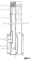
- Fig. 1 shows the central burner in longitudinal section.
- the supply for gas or a gas-air mixture with a high calorific value (1) above it the supply for air (2) and the supply for the gas-air mixture with low calorific value (3).
- the outlet for the gas or gas-air mixture with a high calorific value takes place in the outlet level (1 ').
- the tip of the central burner above (1 ') is made of ceramic.
- the air is led as close as possible to the outlet level (1 '), then diverted and exits in the outlet level (2') as spreading air. Below this is the exit level for the gas-air mixture with a low calorific value (3 ').
Landscapes
- Engineering & Computer Science (AREA)
- Chemical & Material Sciences (AREA)
- Ceramic Engineering (AREA)
- Structural Engineering (AREA)
- Thermal Sciences (AREA)
- Materials Engineering (AREA)
- Physics & Mathematics (AREA)
- Organic Chemistry (AREA)
- Mechanical Engineering (AREA)
- General Engineering & Computer Science (AREA)
- Furnace Details (AREA)
- Carbon And Carbon Compounds (AREA)
- Heat Treatment Of Articles (AREA)
Abstract
Description
Die Erfindung betrifft ein Verfahren zum Beheizen von Schachtöfen mit gasförmigen Brennstoffen, die ausschließlich durch einen Zentralbrenner zugeführt werden, zur Wärmebehandlung von mineralischem Gut.The invention relates to a method for heating shaft furnaces with gaseous fuels, which are supplied exclusively by a central burner, for the heat treatment of mineral material.
Bei den bekannten Verfahren zur Beheizung von Schachtöfen mit gasförmigen Brennstoffen zur Wärmebehandlung von mineralischem Gut wird der Brennstoff durch zentrale und/oder durch seitliche Einspeisung zugeführt.In the known methods for heating shaft furnaces with gaseous fuels for the heat treatment of mineral goods, the fuel is supplied by central and / or by lateral feed.
Bei den Verfahren mit Zentralbrennern wird dem im unteren Drittel des Brennschachts angeordneten Brenner durch getrennte Rohrleitungen Luft und ein Gas-Luft-Gemisch zugeführt. Luft und brennstoffhaltiges Gemisch werden in zwei oder mehr Austrittsebenen wieder ausgeführt. Der Nachteil dieser Verfahren ist, daß insbesondere im Zentralbereich der Steinschüttung, aber auch nahe der Ofenwand überschüssige Luft auftritt. Dadurch wird der Brennvorgang über den Ofenquerschnitt sehr ungleichmäßig. Das zu brennende Gut weist einen qualitätsmindernden zu hohen CO₂-Gehalt auf (Massengehalt von > 3 %).In the processes with central burners, air and a gas-air mixture are fed to the burner arranged in the lower third of the burner shaft through separate pipes. Air and fuel-containing mixture are carried out again in two or more outlet levels. The disadvantage of this method is that there is excess air, particularly in the central region of the stone bed, but also near the furnace wall. This makes the firing process very uneven across the furnace cross-section. The material to be burned has a CO₂ content that lowers the quality (mass content> 3%).
Auch bei dem aus der Zeitschriftenveröffentlichung Zement-Kalk-Gips, Band 37, Nr. 9, September 1984, Seiten 461 bis 464, bekannten Zentralbrenner strömt zwar ein Teil der Kühlluft als Spreizluft zwischen "Obergas" und "Mischgas" aus, der übrige Teil strömt aber als Unterluft hauptsächlich am Brennermantel entlang nach oben.Also in the central burner known from the publication Zement-Kalk-Gips, volume 37, no. 9, September 1984, pages 461 to 464, part of the cooling air flows out as spreading air between "upper gas" and "mixed gas", the rest but flows as an under air mainly up along the burner jacket.
Bei der aus DE-A-20 42 838 bekannten Brennerkonstruktion ist die Kühlung der Brennerspitze unzureichend.In the burner construction known from DE-A-20 42 838, the cooling of the burner tip is insufficient.
Die Verfahren mit seitlicher Zuführung von Brennstoff durch Ringbrenner, wie aus der Deutschen Offenlegungsschrift 24 03 347 bekannt, sollten diesen Nachteil vermeiden. Der mittlere CO₂-Gehalt im erbrannten Produkt kann auch tatsächlich gesenkt werden. Als sehr nachteilig hat sich aber der stark ansteigende Verschleiß der feuerfesten Ausmauerung im Bereich oberhalb der Ringbrenner erwiesen. Die dadurch bedingte Verkürzung der Betriebszeiten der Schachtöfen beeinträchtigt die Wirtschaftlichkeit des Verfahrens erheblich.The methods with lateral supply of fuel by ring burners, as known from German Offenlegungsschrift 24 03 347, should avoid this disadvantage. The average CO₂ content in the product can actually be reduced. However, the sharply increasing wear of the refractory lining in the area above the ring burner has proven to be very disadvantageous. The resulting shortening of the operating times of the shaft furnaces significantly affects the economics of the process.
Es wurde gefunden, daß auch beim Verfahren mit Zentralbrenner eine so gleichmäßige Verteilung der Temperatur über den Schachtofen-Querschnitt erreicht werden kann, daß das aus der Wärmebehandlung mineralischen Guts erhaltene Produkt einen CO₂ -Gehalt von < 2 % aufweist.It was found that even with the process with a central burner, such a uniform distribution of the temperature over the cross-section of the shaft furnace can be achieved that the product obtained from the heat treatment of mineral goods has a CO₂ content of <2%.
Der Erfindung liegt dabei die Aufgabe zugrunde, die Kühlung im Bereich der Brennerspitze zu verbessern.The object of the invention is to improve the cooling in the area of the burner tip.
Zur Lösung dieser Aufgabe werden erfindungsgemäß die Maßnahmen und Merkmale von Anspruch 1 vorgeschlagen.To achieve this object, the measures and features of
Außer den Vorteilen hinsichtlich der längeren Haltbarkeit der feuerfesten Ausmauerung und der verbesserten Produkteigenschaften wird durch das Aufwärmen der Verbrennungsluft, die durch den Brenner geleitet wird, auch eine Energieersparnis erreicht.In addition to the advantages in terms of the longer durability of the refractory lining and the improved product properties, the heating of the combustion air which is passed through the burner also saves energy.
Die folgende Beschreibung soll die Durchführung des Verfahrens an einem Beispiel erläutern.The following description is intended to illustrate the implementation of the method using an example.
In einem Kalkschachtofen üblicher Bauart mit einem lichten Durchmesser von 3700 mm wandert der Kalkstein durch die Vorwärmzone dem Brenner entgegen. Die Entsäuerung findet bei ca. 1100 °C statt. Der gebrannte Kalk gibt seine Temperatur an die aufsteigende Kalkkühlluft ab. Die Ofenleistung liegt bei 150 t Kalk pro Tag. Der Kalkschachtofen ist mit einem Zentralbrenner mit drei Austrittsebenen ausgerüstet.In a lime shaft kiln of conventional design with a clear diameter of 3700 mm, the limestone moves towards the burner through the preheating zone. Deacidification takes place at approx. 1100 ° C. The burnt lime transfers its temperature to the rising lime cooling air. The kiln output is 150 tons of lime per day. The lime shaft kiln is equipped with a central burner with three outlet levels.
Der oberen Austrittsebene wird Gas in Mengen von 220 m³ (i.N.)/h mit einem Heizwert Hu= 32400 kJ/m³ (i.N.) zugeführt. Der untersten Austrittsebene wird ein Gas-Luftgemisch in Mengen von 1240 m³(i.N.)/h mit einem Heizwert Hu = 15900 kJ/m³ (i.N.) zugeführt. Die Gesamtmenge an Gas beträgt 825 m³(i.N.)/h. An Spreizluft werden der mittleren Austrittsebene des Zentralbrenners 3880 m³(i.N.)/h zugeführt. Die Temperatur der Spreizluft beträgt etwa 100 °C.Gas in quantities of 220 m³ (iN) / h with a calorific value H u = 32400 kJ / m³ (iN) is fed to the upper outlet level. A gas-air mixture in quantities of 1240 m³ (iN) / h with a calorific value H u = 15900 kJ / m³ (iN) is fed to the lowest outlet level. The total amount of gas is 825 m³ (iN) / h. 3880 m³ (iN) / h are supplied to the central burner's outlet level of spreading air. The temperature of the spreading air is about 100 ° C.
Damit wird erreicht, daß ein gleichmäßig gebrannter Kalk mit einem Rest-CO₂-Gehalt von 0,5 bis 1,9 % erhalten wird.This ensures that a uniformly burned lime with a residual CO₂ content of 0.5 to 1.9% is obtained.
Da der Brenner erfindungsgemäß mit der gesamten Kühlluft des Systems gekühlt wird, wird der Brennerkopf nicht so heiß wie bei anderen Systemen, die nur mit Gas kühlen. Dadurch werden Betriebssicherheit und Lebensdauer des Brennerkopfes erhöht.Since, according to the invention, the burner is cooled with the entire cooling air of the system, the burner head does not become as hot as with other systems which only cool with gas. This increases the operational reliability and service life of the burner head.
Fig. 1 zeigt den Zentralbrenner im Längsschnitt.Fig. 1 shows the central burner in longitudinal section.
Im unteren Teil des Brenners befinden sich die Zuführung für Gas oder ein Gas-Luft-Gemisch mit hohem Heizwert (1), darüber die Zuführung für Luft (2) und die Zuführung für das Gas-Luft-Gemisch mit niedrigem Heizwert (3).In the lower part of the burner are the supply for gas or a gas-air mixture with a high calorific value (1), above it the supply for air (2) and the supply for the gas-air mixture with low calorific value (3).
Der Austritt für das Gas oder Gas-Luft-Gemisch mit hohem Heizwert erfolgt in der Austrittsebene (1'). Die Spitze des Zentralbrenners oberhalb von (1') besteht aus Keramik. Die Luft wird möglichst nahe an die Austrittsebene (1') geführt, dann umgeleitet und tritt in der Austrittsebene (2') als Spreizluft aus. Darunter befindet sich die Austrittsebene für das Gas-Luft-Gemisch mit niedrigem Heizwert (3').The outlet for the gas or gas-air mixture with a high calorific value takes place in the outlet level (1 '). The tip of the central burner above (1 ') is made of ceramic. The air is led as close as possible to the outlet level (1 '), then diverted and exits in the outlet level (2') as spreading air. Below this is the exit level for the gas-air mixture with a low calorific value (3 ').
Claims (1)
- Method of heating shaft furnaces using gaseous combustion fuels, which are supplied exclusively through a central burner, for the heat treatment of mineral material, gas or a gas-air mixture with a high calorific value being supplied in the top part of the central burner and a gas-air mixture with a low calorific value being supplied in the bottom part of the central burner, and the entire cooling air of the burner system being utilized as spreading air between said two gas streams and exiting in the region of the port-end from the burner.
Applications Claiming Priority (2)
| Application Number | Priority Date | Filing Date | Title |
|---|---|---|---|
| DE3725559A DE3725559C1 (en) | 1987-08-01 | 1987-08-01 | |
| DE3725559 | 1987-08-01 |
Publications (2)
| Publication Number | Publication Date |
|---|---|
| EP0302417A1 EP0302417A1 (en) | 1989-02-08 |
| EP0302417B1 true EP0302417B1 (en) | 1994-06-01 |
Family
ID=6332872
Family Applications (1)
| Application Number | Title | Priority Date | Filing Date |
|---|---|---|---|
| EP88112379A Expired - Lifetime EP0302417B1 (en) | 1987-08-01 | 1988-07-29 | Process and installation for heating shaft furnaces by a central burner |
Country Status (4)
| Country | Link |
|---|---|
| EP (1) | EP0302417B1 (en) |
| AT (1) | ATE106537T1 (en) |
| DE (2) | DE3725559C1 (en) |
| ES (1) | ES2054745T3 (en) |
Cited By (2)
| Publication number | Priority date | Publication date | Assignee | Title |
|---|---|---|---|---|
| CN1975251B (en) * | 2005-11-29 | 2012-08-08 | 特鲁兹·弗卡斯责任有限公司 | Burner beam for a burning kiln for lump material |
| EP3719397A1 (en) | 2019-04-03 | 2020-10-07 | Slovenské magnezitové závody, akciová spolocnost, Jelsava, v skratke SMZ, a.s. Jelsava | Burner for combustion of gaseous fuels in shaft furnace, especially for heat processing of minerals in granular form |
Families Citing this family (2)
| Publication number | Priority date | Publication date | Assignee | Title |
|---|---|---|---|---|
| DE4244130C2 (en) * | 1992-12-24 | 1999-10-28 | Sueddeutsche Kalkstickstoff | Burners for various fuels for burning limestone in a shaft furnace and method for operating the burner |
| DE4341752C2 (en) * | 1993-12-08 | 1995-11-02 | Rheinische Braunkohlenw Ag | Process and central burner for heating shaft furnaces |
Family Cites Families (2)
| Publication number | Priority date | Publication date | Assignee | Title |
|---|---|---|---|---|
| DE2355404A1 (en) * | 1973-11-06 | 1975-05-07 | Shell Int Research | DEVICE FOR HEATING SHAFT STOVES WITH HEATING GAS |
| DE3125320C1 (en) * | 1981-06-27 | 1983-01-13 | Beckenbach, Ulrich, Dipl.-Ing., 4005 Meerbusch | Shaft furnace for burning and sintering piece goods with an internal burner |
-
1987
- 1987-08-01 DE DE3725559A patent/DE3725559C1/de not_active Expired
-
1988
- 1988-07-29 EP EP88112379A patent/EP0302417B1/en not_active Expired - Lifetime
- 1988-07-29 AT AT88112379T patent/ATE106537T1/en not_active IP Right Cessation
- 1988-07-29 DE DE3889801T patent/DE3889801D1/en not_active Expired - Lifetime
- 1988-07-29 ES ES88112379T patent/ES2054745T3/en not_active Expired - Lifetime
Cited By (2)
| Publication number | Priority date | Publication date | Assignee | Title |
|---|---|---|---|---|
| CN1975251B (en) * | 2005-11-29 | 2012-08-08 | 特鲁兹·弗卡斯责任有限公司 | Burner beam for a burning kiln for lump material |
| EP3719397A1 (en) | 2019-04-03 | 2020-10-07 | Slovenské magnezitové závody, akciová spolocnost, Jelsava, v skratke SMZ, a.s. Jelsava | Burner for combustion of gaseous fuels in shaft furnace, especially for heat processing of minerals in granular form |
Also Published As
| Publication number | Publication date |
|---|---|
| EP0302417A1 (en) | 1989-02-08 |
| DE3889801D1 (en) | 1994-07-07 |
| ES2054745T3 (en) | 1994-08-16 |
| DE3725559C1 (en) | 1989-04-13 |
| ATE106537T1 (en) | 1994-06-15 |
Similar Documents
| Publication | Publication Date | Title |
|---|---|---|
| DE3875616T2 (en) | MELTING STOVE. | |
| CH638296A5 (en) | METHOD AND SYSTEM FOR BURNING CARBONOUS RAW MATERIALS BY MEANS OF SOLID FUELS IN A DC-REGENERATIVE CHAMBER. | |
| EP0302417B1 (en) | Process and installation for heating shaft furnaces by a central burner | |
| DE69712372T2 (en) | COMBUSTION OXYGEN ENRICHMENT IN CEMENT STOVE SYSTEMS | |
| DE3136321C2 (en) | Calcining furnace for burning limestone and similar mineral raw materials | |
| DE2751876A1 (en) | PROCESS AND EQUIPMENT FOR BURNING FINE-GRAINED TO DUST-GRAINED GOODS, IN PARTICULAR RAW CEMENT FLOUR | |
| DE2517552A1 (en) | METHOD FOR THERMAL TREATMENT OF FINE-GRAINED GOODS, IN PARTICULAR FOR BURNING CEMENT | |
| DE3145549A1 (en) | Shaft furnace for firing and sintering lumpy material with extraction of circulating gas | |
| DE266935C (en) | ||
| DE4139236C2 (en) | Method and device for melting pig iron | |
| DE3036957C2 (en) | ||
| DE2600254C3 (en) | Method and device for firing small-grain firing material in a shaft furnace | |
| DE2427958B2 (en) | Burners for fluidized bed furnaces | |
| DE503355C (en) | Method and device for heating tunnel ovens | |
| DE19647442A1 (en) | Slaked lime production from limestone burnt in furnace | |
| DE481579C (en) | Process for burning cement with introduction of the raw material in the form of a spray | |
| DE1099436B (en) | Process for the production of cement, especially white cement | |
| DE1111090B (en) | Shaft furnace that can be heated with gas or coal dust for burning limestone, dolomite or magnesite and processes for its operation | |
| DE383761C (en) | Procedure for operating tunnel ovens | |
| AT221411B (en) | Method and device for carbonate decomposition in minerals such as limestone, dolomite, magnesite and the like. Like., By gas heating in a shaft furnace | |
| DE1206346B (en) | Process for firing and sintering cement and similar goods in a shaft furnace | |
| DE459041C (en) | Process and rotary kiln for producing molten cement | |
| AT230791B (en) | Method for heating tunnel ovens | |
| DD211399A1 (en) | DEVICE FOR POST-BURNING COPOLOOD GASES | |
| DE376116C (en) | Cupola furnace with insert and axial, lower wind feed |
Legal Events
| Date | Code | Title | Description |
|---|---|---|---|
| PUAI | Public reference made under article 153(3) epc to a published international application that has entered the european phase |
Free format text: ORIGINAL CODE: 0009012 |
|
| AK | Designated contracting states |
Kind code of ref document: A1 Designated state(s): AT BE CH DE ES FR GB GR IT LI LU NL SE |
|
| 17P | Request for examination filed |
Effective date: 19890105 |
|
| 17Q | First examination report despatched |
Effective date: 19900410 |
|
| GRAA | (expected) grant |
Free format text: ORIGINAL CODE: 0009210 |
|
| AK | Designated contracting states |
Kind code of ref document: B1 Designated state(s): AT BE CH DE ES FR GB GR IT LI LU NL SE |
|
| PG25 | Lapsed in a contracting state [announced via postgrant information from national office to epo] |
Ref country code: NL Effective date: 19940601 |
|
| REF | Corresponds to: |
Ref document number: 106537 Country of ref document: AT Date of ref document: 19940615 Kind code of ref document: T |
|
| REF | Corresponds to: |
Ref document number: 3889801 Country of ref document: DE Date of ref document: 19940707 |
|
| PG25 | Lapsed in a contracting state [announced via postgrant information from national office to epo] |
Ref country code: LU Free format text: LAPSE BECAUSE OF NON-PAYMENT OF DUE FEES Effective date: 19940731 |
|
| ET | Fr: translation filed | ||
| REG | Reference to a national code |
Ref country code: ES Ref legal event code: FG2A Ref document number: 2054745 Country of ref document: ES Kind code of ref document: T3 |
|
| GBT | Gb: translation of ep patent filed (gb section 77(6)(a)/1977) |
Effective date: 19940802 |
|
| ITF | It: translation for a ep patent filed | ||
| REG | Reference to a national code |
Ref country code: GR Ref legal event code: FG4A Free format text: 3012846 |
|
| NLV1 | Nl: lapsed or annulled due to failure to fulfill the requirements of art. 29p and 29m of the patents act | ||
| EAL | Se: european patent in force in sweden |
Ref document number: 88112379.8 |
|
| PLBE | No opposition filed within time limit |
Free format text: ORIGINAL CODE: 0009261 |
|
| STAA | Information on the status of an ep patent application or granted ep patent |
Free format text: STATUS: NO OPPOSITION FILED WITHIN TIME LIMIT |
|
| 26N | No opposition filed | ||
| REG | Reference to a national code |
Ref country code: GB Ref legal event code: IF02 |
|
| APAH | Appeal reference modified |
Free format text: ORIGINAL CODE: EPIDOSCREFNO |
|
| PGFP | Annual fee paid to national office [announced via postgrant information from national office to epo] |
Ref country code: ES Payment date: 20070507 Year of fee payment: 20 |
|
| PGFP | Annual fee paid to national office [announced via postgrant information from national office to epo] |
Ref country code: SE Payment date: 20070523 Year of fee payment: 20 |
|
| PGFP | Annual fee paid to national office [announced via postgrant information from national office to epo] |
Ref country code: BE Payment date: 20070615 Year of fee payment: 20 |
|
| REG | Reference to a national code |
Ref country code: CH Ref legal event code: PCAR Free format text: ISLER & PEDRAZZINI AG;POSTFACH 1772;8027 ZUERICH (CH) |
|
| PGFP | Annual fee paid to national office [announced via postgrant information from national office to epo] |
Ref country code: AT Payment date: 20070515 Year of fee payment: 20 Ref country code: CH Payment date: 20070727 Year of fee payment: 20 |
|
| PGFP | Annual fee paid to national office [announced via postgrant information from national office to epo] |
Ref country code: GB Payment date: 20070725 Year of fee payment: 20 |
|
| PGFP | Annual fee paid to national office [announced via postgrant information from national office to epo] |
Ref country code: IT Payment date: 20070726 Year of fee payment: 20 Ref country code: DE Payment date: 20070801 Year of fee payment: 20 |
|
| PGFP | Annual fee paid to national office [announced via postgrant information from national office to epo] |
Ref country code: FR Payment date: 20070730 Year of fee payment: 20 |
|
| PGFP | Annual fee paid to national office [announced via postgrant information from national office to epo] |
Ref country code: GR Payment date: 20070427 Year of fee payment: 20 |
|
| BE20 | Be: patent expired |
Owner name: SAUERLANDISCHE *KALKINDUSTRIE G.M.B.H. Effective date: 20080729 |
|
| REG | Reference to a national code |
Ref country code: CH Ref legal event code: PL |
|
| REG | Reference to a national code |
Ref country code: GB Ref legal event code: PE20 Expiry date: 20080728 |
|
| EUG | Se: european patent has lapsed | ||
| REG | Reference to a national code |
Ref country code: ES Ref legal event code: FD2A Effective date: 20080730 |
|
| PG25 | Lapsed in a contracting state [announced via postgrant information from national office to epo] |
Ref country code: GB Free format text: LAPSE BECAUSE OF EXPIRATION OF PROTECTION Effective date: 20080728 |
|
| PG25 | Lapsed in a contracting state [announced via postgrant information from national office to epo] |
Ref country code: ES Free format text: LAPSE BECAUSE OF EXPIRATION OF PROTECTION Effective date: 20080730 |