EP0302276A2 - Antenna socket - Google Patents
Antenna socket Download PDFInfo
- Publication number
- EP0302276A2 EP0302276A2 EP88111294A EP88111294A EP0302276A2 EP 0302276 A2 EP0302276 A2 EP 0302276A2 EP 88111294 A EP88111294 A EP 88111294A EP 88111294 A EP88111294 A EP 88111294A EP 0302276 A2 EP0302276 A2 EP 0302276A2
- Authority
- EP
- European Patent Office
- Prior art keywords
- clamp
- antenna socket
- housing
- socket according
- shaft
- Prior art date
- Legal status (The legal status is an assumption and is not a legal conclusion. Google has not performed a legal analysis and makes no representation as to the accuracy of the status listed.)
- Withdrawn
Links
Images

Classifications
-
- H—ELECTRICITY
- H01—ELECTRIC ELEMENTS
- H01R—ELECTRICALLY-CONDUCTIVE CONNECTIONS; STRUCTURAL ASSOCIATIONS OF A PLURALITY OF MUTUALLY-INSULATED ELECTRICAL CONNECTING ELEMENTS; COUPLING DEVICES; CURRENT COLLECTORS
- H01R24/00—Two-part coupling devices, or either of their cooperating parts, characterised by their overall structure
- H01R24/38—Two-part coupling devices, or either of their cooperating parts, characterised by their overall structure having concentrically or coaxially arranged contacts
- H01R24/40—Two-part coupling devices, or either of their cooperating parts, characterised by their overall structure having concentrically or coaxially arranged contacts specially adapted for high frequency
- H01R24/52—Two-part coupling devices, or either of their cooperating parts, characterised by their overall structure having concentrically or coaxially arranged contacts specially adapted for high frequency mounted in or to a panel or structure
- H01R24/525—Outlets
-
- H—ELECTRICITY
- H01—ELECTRIC ELEMENTS
- H01R—ELECTRICALLY-CONDUCTIVE CONNECTIONS; STRUCTURAL ASSOCIATIONS OF A PLURALITY OF MUTUALLY-INSULATED ELECTRICAL CONNECTING ELEMENTS; COUPLING DEVICES; CURRENT COLLECTORS
- H01R2105/00—Three poles
Definitions
- the first section 26 serves to improve the shielding of the area with the inner conductor connections 13, 14 which are surrounded by upstanding housing walls 28, 29, 30 and 31 and are separated from one another by a further housing wall 32.
- the first section 26 fills the area enclosed by the housing walls 28 to 31 upwards and is preferably U-shaped.
- the legs of the U run parallel to the housing walls 28.
- the clamp 25 carries on its underside a contact spring 33, the spring ends 35 of which are bent around the legs of the U and arched outwards so that they contact the inside of the housing walls 28 when the clamp is closed do; see. also Fig. 1 A.
Abstract
Description
Die Erfindung betrifft eine Antennensteckdose nach der Gattung des Anspruchs 1.The invention relates to an antenna socket according to the preamble of claim 1.
Es ist eine Antennensteckdose bekannt (DE-OS 35 30 722), bei der eine Schelle um eine in Einschubrichtung der Koaxialkabel hinter den Innenleiteranschlüssen liegende, quer zur Kabellängsachse verlaufende Achse schwenkbar ist. Die Schelle weist zwei seitliche Zapfen auf, die in seitlichen Führungen senkrecht zur Kabellängsachse verschiebbar am Gehäuse gelagert sind. Im fertig angeschlossenen Zustand der Innenleiter der Koaxialkabel drückt die mittels einer Schraube bewegte Schelle gegen die Außenleiter der Kabel. Die bekannte Antennensteckdose hat den Nachteil, daß die vollständig aufgeklappte Schelle beim Heranführen der Kabelenden aus der Richtung der Schelle die Sicht behindert.An antenna socket is known (DE-OS 35 30 722), in which a clamp can be pivoted about an axis lying behind the inner conductor connections in the insertion direction of the coaxial cables and extending transversely to the longitudinal axis of the cable. The clamp has two lateral pins which are mounted on the housing in lateral guides perpendicular to the longitudinal axis of the cable. When the inner conductor of the coaxial cable is fully connected, the clamp moved by means of a screw presses against the outer conductor of the cable. The known antenna socket has the disadvantage that the fully opened clamp hinders the view when the cable ends are brought in from the direction of the clamp.
Ein weiterer Nachteil besteht darin, daß die Schelle zum vollständigen Aufklappen von Hand nach vorn gezogen werden muß, weil anderenfalls ein zur Arretierung der aufgeklappten Schelle dienender Anschlag das vollsdtändige Aufklappen verhindert.Another disadvantage is that the clamp must be pulled forward by hand to fully open it, because otherwise a stop serving to lock the opened clamp prevents it from being fully opened.
Der Erfindung liegt die Aufgabe zugrunde, eine Antennensteckdose der gattungsgemäßen Art derart weiterzubilden, daß die Schelle im vollständig geöffneten Zustand den für das Heranführen und Anschließen der Koaxialkabel beanspruchten Bereich der Antennensteckdose völlig freilegt. Eine weitere Aufgabe besteht darin, das Öffnen der Schelle bis zum vollständigen Aufklappen zu erleichtern.The invention has for its object to develop an antenna socket of the generic type in such a way that the clamp fully exposed in the fully opened state for the approach and connection of the coaxial cable area of the antenna socket. Another task is to make it easier to open the clamp until it is fully opened.
Diese Aufgabe wird bei einer gattungsgemäßen Antennensteckdose durch die kennzeichnenden Merkmale des Anspruchs 1 gelöst.This object is achieved in a generic antenna socket by the characterizing features of claim 1.
Die mit der Erfindung erzielten Vorteile bestehen insbesondere darin, daß die Schelle im vollständig aufgeklappten Zustand weder eine Sichtbehinderung noch eine Behinderung beim Hantieren mit den Koaxialkabelenden darstellt. Damit die Schelle bei gelöster Befestingungsschraube immer eine Lage einnimmt, die das vollständige Aufklappen ohne Behinderung zuläßt und die Schelle in der Aufklappstellung arretiert, steht das freie Hebelende der Schelle unter der Kraft einer Druckfeder, die in einem Schacht des Gehäuses der Antennensteckdose untergebracht ist.The advantages achieved by the invention are, in particular, that the clamp, in the fully opened state, does not constitute a visual impairment or a hindrance when handling the coaxial cable ends. So that the clamp always takes a position when the fastening screw is loosened, which allows it to be opened completely without hindrance and locks the clamp in the open position, the free lever end of the clamp is under the force of a compression spring which is accommodated in a shaft in the housing of the antenna socket.
Ein bevorzugtes Anwendungsgebiet für die erfindungsgemäße Antennensteckdose sind Breitbandkommunikationsanlagen für Frequenzen bis zu über 1 MHz.A preferred area of application for the antenna socket according to the invention is broadband communication systems for frequencies up to more than 1 MHz.
Ein Ausführungsbeispiel der Erfindung ist in der Zeichnung an Hand mehrerer Figuren dargestellt und im folgenden näher erläutert.An embodiment of the invention is shown in the drawing using several figures and explained in more detail below.
Es zeigen
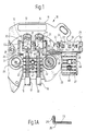
- Fig. 1 eine Ansicht einer erfindungsgemäßen Antennensteckdose mit aufgeklappter Schelle,
- Fig. 1A eine Schnittansicht der Schelle gemäß dem Schnittverlauf IA in Fig. 1,
- Fig. 2 eine Ansicht der Schelle von unten,
- Fig. 3 eine Schnittansicht der Schelle nach Fig. 2 gemäß dem Schnittverlauf III und
- Fig. 4 eine Schnittansicht der Schelle nach Fig. 2 gemäß dem Schnittverlauf IV.
- 1 is a view of an antenna socket according to the invention with the clamp open,
- 1A is a sectional view of the clamp according to the section IA in Fig. 1,
- 2 is a view of the clamp from below,
- Fig. 3 is a sectional view of the clamp of FIG. 2 according to the section III and
- Fig. 4 is a sectional view of the clamp of FIG. 2 according to the section IV.
In Fig. 1 weist eine Antennensteckdose 10 ein Gehäuse 11 auf, dessen Oberseite 12 zwei Innenleiteranschlüsse 13, 14 für Innenleiter 15, 16 zweier an ihren Enden abisolierter Koaxialkabel 17, 18 trägt. Die auf eine bestimmte Länge von der Außenisolation 19, 20 befreiten Außenleiter 22, 23 der Koaxialkabel ruhen auf Stegen 24, die auf der Oberseite 12 der Antennensteckdose quer zur Längsrichtung der Koaxilkabel angeordnet sind. Die Stege 24 sorgen in Verbindung mit einer Schelle 25 für eine gute elektrische Kontaktgabe und eine Zugentlastung der Koaxialkabel. Die Schelle 25 weist einen rechteckförmigen ersten Abschnitt 26 auf, der in einen zweiten Abschnitt 27 übergeht. Der erste Abschnitt 26 dient zur Verbesserung der Abschirmung der Bereiches mit den Innenleiteranschlüssen 13, 14, die von hochstehenden Gehäusewänden 28, 29, 30 und 31 umgeben sind und durch eine weitere Gehäusewand 32 voneinander getrennt sind. Der erste Abschnitt 26 füllt bei geschlossener Schelle 25 den von den Gehäusewänden 28 bis 31 umschlossenen Bereich nach oben ab und ist vorzugsweise U-förmig ausgebildet. Die Schenkel des U verlaufen parallel zu den Gehäusewänden 28. Die Schelle 25 trägt an ihrer Unterseite eine Kontaktfeder 33, deren Federenden 35 um die Schenkel des U gebogen und nach außen gewölbt sind, so daß sie bei geschlossener Schelle mit den Innenseiten der Gehäusewände 28 Kontakt machen; vgl. auch Fig. 1 A. Die Kontaktfeder 33 weist in ihrem mittleren Bereich Kontaktlappen 50, 51, 52 auf, die nach außen gewölbt sind und bei zugeklappter Schelle auf metallischen Druckplatten 53, 54 der Innenleiteranschlüsse 13, 14 und auf der weiteren Gehäusewand 32 aufliegen. Die Schelle 25 weist einen damit fest verbundenen Hebel 36 auf (vgl. auch Fig. 2), der an seinem freien Ende einen senkrecht zur Längsachse des Hebels stehenden zylindrischen Zapfen 37 trägt. Die Achse 34 des Zapfens bildet die Schwenkachse für die Schelle 25. Der Zapfen 37 paßt in einen senkrecht auf der Oberseite 12 angeordneten Schacht 38, der an seinem oberen Ende geschlossen ist, so daß der Zapfen innerhalb des Schachtes parallel zu dessen Längsachse verschiebbar, aber gegen ein Herausfallen gesichert ist. Der Schacht 38 bildet zusammen mit einem weiteren Schacht 39 eine T-förmige Führung 40. In dem weiteren Schacht 39 wird der Hebel 36 feführt. Zwischen dem Boden des Schachtes 38 und dem Zapfen 37 bzw. dem freien Ende 41 des Hebels 36 befindet sich eine Druckfeder 42, die sich bei aufgeklappter Schelle an einer Schräge 43 an der Oberseite des Hebels 36 abstützt und die dafür sorgt, daß die Schelle im vollständig aufgeklappten Zustand die in Fig. 4 gezeigte Stellung beibehält. Außerdem bewirkt die Druckfeder 42 ein Anheben der Schelle vor dem Öffnen derselben. Damit wird das Öffnen und das Schwenken der Schelle erleichtert.In Fig. 1, an
Die Schelle trägt an ihrer Unterseite quer zu ihrer Längsachse schmale Stege 45 (Fig. 3), die mit den Stegen 24 des Gehäuses 11 korrespondieren. Zum Festlegen der Schelle enthält diese eine darin frei drehbare Mutter 46, die auf einen aufrechstehenden Gewindebolzen 47 des Gehäuses 11 aufschraubbar ist. Weiterhin enthält die Schelle 25 noch eine Öffnung 48 zum freien Durchtritt einer in der Zeichnung nicht dargestellten Schraube, die zum Festhalten einer Abdeckplatte für die Antennensteckdose dient und zu diesem Zweck in eine Gewindeöffnung 49 eines hohlzylindrischen Sockels 50 des Gehäuses 11 einschraubbar ist. Zum Befestigen der Kontaktfeder 33 an der Schelle 25 sind beispielsweise vier Niete 55 vorgesehen; vgl. Fig. 2.On its underside, the clamp carries narrow webs 45 (FIG. 3) transverse to its longitudinal axis, which correspond to the
Das Gehäuse besteht vorzugsweise aus einem elektrisch leitenden Werkstoff oder aus einem an der Oberfläche metallisierten Kunststoff.The housing preferably consists of an electrically conductive material or of a plastic metallized on the surface.
Claims (7)
Applications Claiming Priority (2)
| Application Number | Priority Date | Filing Date | Title |
|---|---|---|---|
| DE8710240U | 1987-07-25 | ||
| DE8710240U DE8710240U1 (en) | 1987-07-25 | 1987-07-25 |
Publications (2)
| Publication Number | Publication Date |
|---|---|
| EP0302276A2 true EP0302276A2 (en) | 1989-02-08 |
| EP0302276A3 EP0302276A3 (en) | 1989-09-06 |
Family
ID=6810472
Family Applications (1)
| Application Number | Title | Priority Date | Filing Date |
|---|---|---|---|
| EP88111294A Withdrawn EP0302276A3 (en) | 1987-07-25 | 1988-07-14 | Antenna socket |
Country Status (3)
| Country | Link |
|---|---|
| EP (1) | EP0302276A3 (en) |
| DE (1) | DE8710240U1 (en) |
| DK (1) | DK409988A (en) |
Cited By (1)
| Publication number | Priority date | Publication date | Assignee | Title |
|---|---|---|---|---|
| EP1703593A1 (en) * | 2005-03-16 | 2006-09-20 | Hirschmann Multimedia Electronics GmbH | Clamping technique for the inner conductor of a coaxial line for the connection to an antenna socket outlet |
Families Citing this family (2)
| Publication number | Priority date | Publication date | Assignee | Title |
|---|---|---|---|---|
| IT1217384B (en) * | 1988-03-31 | 1990-03-22 | Helman Elettronica Spa | TERMINAL FOR CONNECTION OF COAXIAL CABLES |
| DE102005043136A1 (en) * | 2005-09-12 | 2007-03-22 | Hirschmann Electronics Gmbh | Antenna box for removable connection of cables and high frequency technical device at antenna has base plate which has contact unit with electrically non-conductive material whereby at contact unit spring clamp is arranged |
Citations (2)
| Publication number | Priority date | Publication date | Assignee | Title |
|---|---|---|---|---|
| DE2238092A1 (en) * | 1972-08-02 | 1974-02-14 | Siemens Ag | ANTENNA SOCKET |
| WO1987001520A1 (en) * | 1985-08-28 | 1987-03-12 | Hans Kolbe & Co. | Aerial plug socket |
Family Cites Families (1)
| Publication number | Priority date | Publication date | Assignee | Title |
|---|---|---|---|---|
| DE1616527B1 (en) * | 1968-03-08 | 1971-10-21 | Siemens Ag | Antenna socket with a housing made of insulating material |
-
1987
- 1987-07-25 DE DE8710240U patent/DE8710240U1/de not_active Expired
-
1988
- 1988-07-14 EP EP88111294A patent/EP0302276A3/en not_active Withdrawn
- 1988-07-22 DK DK409988A patent/DK409988A/en not_active Application Discontinuation
Patent Citations (2)
| Publication number | Priority date | Publication date | Assignee | Title |
|---|---|---|---|---|
| DE2238092A1 (en) * | 1972-08-02 | 1974-02-14 | Siemens Ag | ANTENNA SOCKET |
| WO1987001520A1 (en) * | 1985-08-28 | 1987-03-12 | Hans Kolbe & Co. | Aerial plug socket |
Cited By (1)
| Publication number | Priority date | Publication date | Assignee | Title |
|---|---|---|---|---|
| EP1703593A1 (en) * | 2005-03-16 | 2006-09-20 | Hirschmann Multimedia Electronics GmbH | Clamping technique for the inner conductor of a coaxial line for the connection to an antenna socket outlet |
Also Published As
| Publication number | Publication date |
|---|---|
| DK409988A (en) | 1989-01-26 |
| DE8710240U1 (en) | 1987-09-17 |
| DK409988D0 (en) | 1988-07-22 |
| EP0302276A3 (en) | 1989-09-06 |
Similar Documents
| Publication | Publication Date | Title |
|---|---|---|
| DE102015104625B4 (en) | conductor terminal | |
| EP0083738B1 (en) | Electrical cable junction unit equipped with cutting terminals | |
| EP0496972A1 (en) | Plug connector especially for removable connection of electric conductors | |
| DE69923651T2 (en) | connecting spring | |
| DE60310351T2 (en) | Arrangement for the electrical connection of a modular electrical switching device to a connecting comb or a similar part | |
| EP0695008B1 (en) | Universal cable clamping device | |
| DE2452091C3 (en) | Device for clamping conductors to be electrically connected to one another | |
| EP0271490B1 (en) | Aerial plug socket | |
| EP0302276A2 (en) | Antenna socket | |
| EP0148334A2 (en) | Device for the attachment of accessories on the wall of a lighting fixture | |
| DE10205614B4 (en) | connection adapter | |
| DE3530721C2 (en) | ||
| EP0704931A1 (en) | Terminal clamping device for connecting cables to bars | |
| DE19610610A1 (en) | Arrangement for connecting electrical conductor to insulation piercing contact | |
| DE2706887C3 (en) | ||
| DE4126604A1 (en) | Electrical connecting terminal for antenna plug connector - has metal press as contact element loaded by clamping screw to securely engage with connecting wire | |
| DE2733200B2 (en) | Antenna socket | |
| DE4217906A1 (en) | Cable entry socket with stress relief esp. for telecommunication - has opening through body with sealing segments and integral destressing element exerting vertical grip on cable | |
| EP4150718A1 (en) | Insulating body for screw and crimp contacts | |
| DE1910025C3 (en) | Clamping device for connecting coaxial cables | |
| DE102022111780A1 (en) | Strain relief device, set of a conductor terminal and a strain relief device and conductor terminal with a housing and with a strain relief device | |
| DE2827143A1 (en) | Locking device for contacts of multipole connector - has contact with constriction engaged by spring arm on cover | |
| AT407595B (en) | RECORDING PART FOR A MULTIPOLE CONNECTOR | |
| DE2907888A1 (en) | Multiple connection plug and socket - has socket with hinged cover which forces insulated wires onto cutting arms of contact elements | |
| DE3033105C2 (en) | Short-circuiting device for insulated overhead lines |
Legal Events
| Date | Code | Title | Description |
|---|---|---|---|
| PUAI | Public reference made under article 153(3) epc to a published international application that has entered the european phase |
Free format text: ORIGINAL CODE: 0009012 |
|
| AK | Designated contracting states |
Kind code of ref document: A2 Designated state(s): AT CH DE FR LI NL SE |
|
| PUAL | Search report despatched |
Free format text: ORIGINAL CODE: 0009013 |
|
| AK | Designated contracting states |
Kind code of ref document: A3 Designated state(s): AT CH DE FR LI NL SE |
|
| STAA | Information on the status of an ep patent application or granted ep patent |
Free format text: STATUS: THE APPLICATION IS DEEMED TO BE WITHDRAWN |
|
| 18D | Application deemed to be withdrawn |
Effective date: 19900307 |