EP0302264B1 - Kraftfahrzeug-Kühlmittelfluss-Steuerung - Google Patents
Kraftfahrzeug-Kühlmittelfluss-Steuerung Download PDFInfo
- Publication number
- EP0302264B1 EP0302264B1 EP88111168A EP88111168A EP0302264B1 EP 0302264 B1 EP0302264 B1 EP 0302264B1 EP 88111168 A EP88111168 A EP 88111168A EP 88111168 A EP88111168 A EP 88111168A EP 0302264 B1 EP0302264 B1 EP 0302264B1
- Authority
- EP
- European Patent Office
- Prior art keywords
- flow
- fluid flow
- controlling means
- flow control
- flow controlling
- Prior art date
- Legal status (The legal status is an assumption and is not a legal conclusion. Google has not performed a legal analysis and makes no representation as to the accuracy of the status listed.)
- Expired - Lifetime
Links
Images

Classifications
-
- B—PERFORMING OPERATIONS; TRANSPORTING
- B60—VEHICLES IN GENERAL
- B60H—ARRANGEMENTS OF HEATING, COOLING, VENTILATING OR OTHER AIR-TREATING DEVICES SPECIALLY ADAPTED FOR PASSENGER OR GOODS SPACES OF VEHICLES
- B60H1/00—Heating, cooling or ventilating devices
- B60H1/00485—Valves for air-conditioning devices, e.g. thermostatic valves
-
- F—MECHANICAL ENGINEERING; LIGHTING; HEATING; WEAPONS; BLASTING
- F01—MACHINES OR ENGINES IN GENERAL; ENGINE PLANTS IN GENERAL; STEAM ENGINES
- F01P—COOLING OF MACHINES OR ENGINES IN GENERAL; COOLING OF INTERNAL-COMBUSTION ENGINES
- F01P7/00—Controlling of coolant flow
- F01P7/14—Controlling of coolant flow the coolant being liquid
-
- G—PHYSICS
- G05—CONTROLLING; REGULATING
- G05D—SYSTEMS FOR CONTROLLING OR REGULATING NON-ELECTRIC VARIABLES
- G05D7/00—Control of flow
- G05D7/01—Control of flow without auxiliary power
- G05D7/0126—Control of flow without auxiliary power the sensing element being a piston or plunger associated with one or more springs
- G05D7/0133—Control of flow without auxiliary power the sensing element being a piston or plunger associated with one or more springs within the flow-path
-
- Y—GENERAL TAGGING OF NEW TECHNOLOGICAL DEVELOPMENTS; GENERAL TAGGING OF CROSS-SECTIONAL TECHNOLOGIES SPANNING OVER SEVERAL SECTIONS OF THE IPC; TECHNICAL SUBJECTS COVERED BY FORMER USPC CROSS-REFERENCE ART COLLECTIONS [XRACs] AND DIGESTS
- Y10—TECHNICAL SUBJECTS COVERED BY FORMER USPC
- Y10T—TECHNICAL SUBJECTS COVERED BY FORMER US CLASSIFICATION
- Y10T137/00—Fluid handling
- Y10T137/0318—Processes
- Y10T137/0402—Cleaning, repairing, or assembling
- Y10T137/0441—Repairing, securing, replacing, or servicing pipe joint, valve, or tank
- Y10T137/0447—Including joint or coupling
-
- Y—GENERAL TAGGING OF NEW TECHNOLOGICAL DEVELOPMENTS; GENERAL TAGGING OF CROSS-SECTIONAL TECHNOLOGIES SPANNING OVER SEVERAL SECTIONS OF THE IPC; TECHNICAL SUBJECTS COVERED BY FORMER USPC CROSS-REFERENCE ART COLLECTIONS [XRACs] AND DIGESTS
- Y10—TECHNICAL SUBJECTS COVERED BY FORMER USPC
- Y10T—TECHNICAL SUBJECTS COVERED BY FORMER US CLASSIFICATION
- Y10T137/00—Fluid handling
- Y10T137/7722—Line condition change responsive valves
- Y10T137/7781—With separate connected fluid reactor surface
- Y10T137/7784—Responsive to change in rate of fluid flow
- Y10T137/7792—Movable deflector or choke
-
- Y—GENERAL TAGGING OF NEW TECHNOLOGICAL DEVELOPMENTS; GENERAL TAGGING OF CROSS-SECTIONAL TECHNOLOGIES SPANNING OVER SEVERAL SECTIONS OF THE IPC; TECHNICAL SUBJECTS COVERED BY FORMER USPC CROSS-REFERENCE ART COLLECTIONS [XRACs] AND DIGESTS
- Y10—TECHNICAL SUBJECTS COVERED BY FORMER USPC
- Y10T—TECHNICAL SUBJECTS COVERED BY FORMER US CLASSIFICATION
- Y10T137/00—Fluid handling
- Y10T137/7722—Line condition change responsive valves
- Y10T137/7837—Direct response valves [i.e., check valve type]
- Y10T137/7869—Biased open
Definitions
- the present invention relates to a flow controller for use in a vehicle coolant circuit.
- the coolant is circulated by an engine driven pump. Since the engine speed varies during vehicle operation, the flow rate of coolant in the heater circuit changes as well. Because the heat output of a heat exchanger is determined primarily by the temperature and flow rate of coolant through the exchanger, the heat output of the heater core also varies with engine speed. The output of the heater with the engine idling and the vehicle at a standstill is substantially less than the output of the heater with the engine turning at a substantially higher RPM, i.e., when the vehicle is traveling at highway speeds.
- the useful life of the heater core is substantially reduced if high coolant flow rates are allowed to proceed through the heater.
- the reason that the useful life is diminished at high flow rates is due to particles and other matter which are carried by the coolant.
- This matter may comprise normal residue left in the engine block coolant passages from the manufacturing process including sand left from the casting process and metal shavings left from the machining processes. These particles and other matter act as abrasives and abrade the inside of the passages in the heater core which are usually constructed of rather thin materials in order to promote heat exchange. At high fluid flow rates, this normal abrasion process can be greatly accelerated thus reducing the life of the heater.
- GB-A-759 220 describes a valve for a heater system of an automobile.
- the device is designed to provide a uniform flow of water independent of pressure variations caused be engine speed changes.
- the device consists of a central stationary tapered pin which forms with an opening in a large moveable diaphragm, a variable orifice.
- the diaphragm is biased by a spring and a weight.
- the diaphragm and variable orifice lie intermediate between the inlet and outlet of the valve. As the pressure increases, the diaphragm moves on the tapered pin such as to reduce the orifice area and thus control the flow rate.
- first position of the flow controlling means In a first position of the flow controlling means, at low fluid flow rates, the fluid flow proceeds normally. With increased fluid flow the fluid control means moves to a second position in which fluid flow is restricted.
- the change from first to second position can be very rapid and can result in valve bounce or other shocks to the system.
- the object of the present invention is to provide a new and improved flow control for the passenger compartment heating circuit which allows the change from substantially unimpeded flow of coolant through the heater at low engine speeds to restrict flow through the heater at high engine speeds without causing shocks to the system.
- the disclosed control at low engine speeds i.e. engine idle, the amount of heat available from the engine coolant is not substantially reduced by flow restrictions in the coolant circuit.
- a flow control device controlling fluid flow in a vehicle heating system, comprising; a structure defining an inlet and an outlet; said structure further defining a fluid flow controlling chamber disposed intermediate said inlet and said outlet; fluid flow controlling means disposed in said chamber and moveable between first and second positions; biasing means urging said flow controlling means towards the first position at which fluid flow between said inlet and said outlet is substantially unimpeded by said flow controlling means; said flow controlling means defining an orifice, whereby a force is developed on said flow controlling means in opposition to said biasing means, characterized in that said force is developed by fluid flow through said orifice; said force overcoming said biasing means when fluid flow from said inlet to said outlet reaches a predetermined level such that at fluid flow rates below said predetermined level, said flow controlling means is maintained in said first position and at higher flow rates than said predetermined level said flow controlling means moves to its second position; a valve seat is arranged so that when said flow controlling means is in said second position, fluid flow through said orifice is
- the flow control chamber is preferably cylindrical and defines an annular seat that communicates with the outlet.
- the flow control member which is slidably movable towards and away from the seat includes a somewhat annular segment defining a centrally located through hole that is substantially, axially aligned with the seat.
- the segment is supported for sliding movement towards and away from the seat by a plurality of guides that extend in the axial direction and which are preferably attached to a periphery of the segment at spaced locations.
- the diameter of the annular segment is less than the diameter of the flow controlling chamber so that peripheral passages are defined between the wall of the chamber and the periphery of the segment.
- the guides are dimensioned such that the segment is maintained in a substantially centered position within the chamber.
- Each of the guides have a longitudinal extent which inhibits twisting of the segment within the chamber and, as a result, the through aperture defined by the segment remains substantially, axially aligned with the seat regardless of the position of the segment within the chamber.
- the flow control member has a spider-like appearance with four longitudinal legs extending axially from a peripheral rim of the segment.
- the flow controlling segment defines a face that is located in a confronting relationship with the seat.
- the face includes projections that extend axially from the face and which are aligned with the seat.
- the annular flow control segment is elastomeric in construction and may be made from rubber, plastic or other suitable material.
- the projections define clearance regions between the seat and the flow control segment and allow fluid to travel between the confronting face defined by the flow control member and the seat. Fluid flow can also flow through the aperture defined by the member as well as through the peripheral flow passages defined between the rim of the segment and the inner wall of the chamber.
- the fluid exerts a force on the member deforming it and causing at least portions of the confronting surface to engage the seat inhibiting or substantially reducing the extent of the clearance region thereby substantially diminishing the flow of fluid between the seat and the confronting face of the member.
- the confronting face of the member, the projections and seat cooperate to function as a flow responsive variable orifice.
- the housing comprises a main body and a fitting assembly which snap together and are maintained in their assembled condition by a resilient locking member.
- the locking member is carried by the fitting assembly and engages structure defined by the main body which prevents the main body and a fitting from separating once the members are snapped together.
- the main body includes a plurality, preferably four, locking lugs which are supported a spaced distance beyond an end of the main body.
- the lugs are supported by axially extending support tabs.
- Each tab is arcuate in cross section and together define a segmented groove sized to receive a resilient retaining ring carried by the fitting assembly.
- the groove defines a diameter that is larger than a diameter defined by radial surfaces forming part of the lugs.
- the fitting assembly includes a groove for receiving the resilient retaining ring when it is compressed. To assemble the components, the ring is compressed into the groove formed in the fitting assembly.
- the end of the fitting assembly is pushed into an end bore defined by the main body and when in position, the retaining ring springs outwardly and engages the groove defined by the support tabs. Access openings are defined between the tabs which enable one to recompress the retaining ring in order to separate the main body from the fitting assembly.
- the present invention provides an effective control for restricting high flow rates through a heater core.
- the disclosed construction is inexpensive to manufacture and the housing itself may be molded from a material such as glass-filled nylon. Very little if any machining is required.
- the flow control member is an assembly of two pieces.
- One piece comprises a cage having a plurality of axially extending legs defining guides which slidably support the assembly within the controller chamber.
- the other piece comprises an elastomeric flow control element that is received and is captured within the cage.
- the flow control element performs a function of the flow control segment of the one-piece embodiment.
- the flow controlling element is annular and includes a face located in confronting relation with the valve seat. A plurality of projections extend axially from the face and are abuttable engageable with the seat when the flow control assembly moves to the first position. Fluid flow through and around the flow control element when the element initially engages the seat.
- the support cage is preferably constructed of a rigid material such as rigid plastic.
- the flow control element is deformed in order to insert the element into the cage and once installed is captured within the cage by spaced apart, parallel engaging support rings which engage the element.
- the individual pieces that make up the flow control member can be individually replaced should one of them fail.
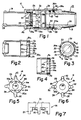
- Figure 1 illustrates the overall construction of a flow controller assembly constructed in accordance with one preferred embodiment of the invention.
- the flow controller is specifically adapted to control coolant flow to or from a passenger compartment heater (not shown) in a vehicle.
- the flow controller includes a main body 10, a fitting assembly 12 and a flow control member 14.
- the main body 10 defines a fitting 16 to which a hose or other suitable conduit is fastened as by a clamp (not shown).
- the fitting assembly 12, in the illustrated embodiment, includes a tapered nose 18 which is adapted to engage or mate with structure forming part of a heater core or another heater control member (not shown).
- the illustrated flow controller may be directly attached to either an input or output port of the passenger compartment heater core, or alternately, may be attached to or form part of a variable heater valve such as that shown in U.S. Patent No. 4,469,133, which is owned by the present assignee and hereby incorporated by reference.
- the flow controller shown in Figure 1 may also be an integral part of a variable heat control valve forming part of a passenger compartment heating circuit.
- the main body 10 defines a seat 20 including an opening 22.
- An enlarged diameter segment 24 defines a flow controlling chamber 26 in which the flow control member 14 is movably supported.
- the opening 22 communicates with an outlet passage 28 defined by the fitting 16. Coolant enters the flow control assembly by way of an inlet passage 30 defined by the fitting assembly 12.
- the control member 14 moves towards and away from the valve seat 20 in response to a sensed pressure differential generated across the flow control element 14 by the coolant flowing from the passage 30 to the passage 28.
- the fitting assembly 12 is removably attached to one end of the main body 10.
- the main body 10 includes an enlarged diameter end section 34 defining an end bore 36 that is adapted to receive a narrow diameter end section 38 formed on the left end (as viewed in Figure 1) of the fitting 12.
- An O-ring 40 received in an O-ring groove 42 prevents or inhibits fluid leakage between the main body 10 and the fitting assembly 12.
- the fitting assembly 12 is held to the main body 10 by a resilient retaining ring 46.
- the retaining ring 46 is receivable in a groove 48 formed in the fitting 12.
- the retaining ring 46 and associated groove 48 are sized so that when the ring is radially compressed, it can fit within the groove 48 so that no portion of the ring 46 will extend beyond an outer surface 38a of the fitting end section 38.
- the retaining ring 46 when in its free state, has a diameter that is larger than the diameter of the end section 38.
- the main body 16 includes structure engageable by at least portions of the retaining ring 46 which prevent retraction or removal of the fitting 12 once the end section 38 is inserted into the end bore 36 defined by the body 10.
- the right end (as viewed in Figure 1) of the main body 10 includes a locking structure engageable by the locking ring 46 carried by the fitting 12 which cooperate to maintain the body 10 and fitting 12 in their assembled positions shown, once the two members are snapped together.
- the structure comprises a plurality of arcuate locking lugs 50 and arcuate, axially extending support tabs 52.
- each lug 50 is supported a space distance beyond partial end face segments 34a of the end section 34 by the axially extending support tabs 52.
- the lugs 50 each define an internal axial surface 50a that conforms in dimension substantially to the bore surface 36.
- Each tab 52 has an inner axial surface 52a which together define a diameter that is larger than the diameter of the bore surface 36.
- the tabs 52 define a segmented groove which receives and confines the retaining ring 46 when the fitting 12 is installed.
- An opening 56 is defined between each lug 50 and the associated end surface segment 34a of the main body 10.
- each lug defines a chamfered surface 58.
- the disclosed construction enables the fitting 12 to be readily inserted into the open end of the main body 10.
- the chamfered surfaces 58 of the lugs 50 urge the retaining ring 46 inwardly into the retaining ring groove 48. After the retaining ring 46 passes the lugs 50, it springs outwardly and engages the segmented groove defined by the four tabs 52. Once the retaining ring 46 expands outwardly, removal or disassembly of the fitting 12 from the main body 10 is substantially resisted. In effect, the fitting 12 is locked to the main body 10. In order to disassemble the fitting 12 from the main body 12, the retaining ring 46 must be compressed (via the openings 56).
- the member 14 is slidably mounted within the flow controlling chamber 26, primarily defined by the main body 16.
- the flow control member 14 moves towards and away from the valve seat 20 depending on the rate of fluid flow between the inlet passage 30 and the outlet passage 28.
- the flow control member 14 is captured within the chamber 26 by an annular retaining member 80 which is press fitted into the chamber 26 after the flow control member 14 is installed.
- a spring 86 urges the flow control member 14 away from the seat 20 and into abutting engagement with the retainer 80.
- the member 14 is made of an elastomeric material such as rubber or related compound.
- the element 14 includes a somewhat annular portion 88 defining a central aperture 90.
- Four spider-like legs 92 extend axially from a periphery of the portion 88 and engage a rim 80a of the retainer 80. Thickened reinforcing sections 92a rigidize the legs 92.
- the diameter of the annular portion 88 is less than the diameter of the chamber 26 so that four flow passages, indicated generally by the reference character 94, are defined between the periphery of the portion 88, the legs 92 and an inner wall 26a of the chamber 26.
- a plurality of short stand-offs 100 are positioned on the left face 14a (as viewed in Figure 1) of the member 14.
- the stand-offs 100 are positioned in a circle having a diameter that is substantially the diameter of the axial surface 20a defined by the seat 20.
- the stand-offs contact the axial surface 20a when the member 14 moves a predetermined distance to the left (as viewed in Figure 1).
- coolant flow from the inlet passage 30 to the outlet passsage 28 is restricted to the aperture 90 and small clearance spaces defined between the face 14a of the member 14 and the seating surface 20a.
- the additional force generated on the member 14 will cause it to deform (since it is elastomeric) and will cause at least portions of the left face 14a of the member 14 to contact the seating surface 20a thus gradually closing off the clearance regions provided by the stand-offs 100 between the seat surface 20a and the left face 14a.
- the clearance regions will be eliminated and substantially all coolant flow will proceed through the aperture 90.
- the face 14a, stand-offs 100 and seat surface 20a serve as a variable orifice.
- the flow controller functions as a multi-stage restriction in which at least one of the stages it functions as a flow responsive variable restrictor.
- the disclosed construction can be made virtually entirely of a plastic or other synethic material such as glass filled nylon.
- a plastic or other synethic material such as glass filled nylon.
- the use of such a material provides a flow control that is inexpensive to manufacture while being chemically inert to the materials and/or chemicals normally found in a vehicle coolant system.
- the flow control member 14 in this embodiment is a unitary structure, preferably molded from a soft elastomeric material.
- the legs 92 are integrally molded with the annular portion 88.
- FIGS 8-13 illustrate another embodiment of the invention.
- an inlet housing 112 is releasably connected to a mounting adapter 110.
- the adapter 110 is fixed to the end of a tube 116.
- the tube 116 may form part of the coolant circuit for the passenger heater (not shown).
- the flow controller is mounted at a location remote from the actual heat exchanger, enhancing its serviceability and maintenance.
- existing heater constructions do not have to be modified to incorporate the flow controller.
- the controller can easily be attached to the end of an existing coolant conduit where it can be easily serviced or replaced should the need arise.
- the mounting adapter 110 is fixedly secured to the end of the tube 116. If the adapter is metal, it can be brazed or welded to the end of the tube. If constructed of plastic a suitable adhesive would be used to effect the mounting. As in the embodiment shown in Figure 1, the adapter includes a groove 48′ for receiving the locking ring 46 during the assembly process. The mounting adapter 110 also includes an O-ring groove 42′ and carries the sealing O-ring 40.
- the mounting adapter 110 defines an integral valve seat 120.
- the inlet housing 112 defines an inlet nipple 113 which can be conveniently connected to a coolant hose (not shown).
- the inlet housing 112 slidably supports a flow control sub-assembly 114 and includes an enlarged diameter section 124 which at least partially defines a flow control chamber 126.
- a spring 125 biases the flow control sub-assembly 114 away from the seat 120.
- the flow control sub-assembly 114 in the alternate embodiment is of a two piece construction and includes a support cage 114a (shown best in Figures 9-11) an elastomeric flow control element 114b (shown best in Figures 12-13).
- the cage is similar in configuration to the flow control member 14 (shown in Figures 5-7).
- the cage includes four spaced apart spider-like legs 130 which are abuttably engageable with a shoulder 134 defined by the inlet housing 112.
- coolant flows from the inlet nipple 113 to the tube 116 through a central aperture 140 defined by the flow controlling element 114b and between flow passages defined between the legs 132 and the inside of the chamber 126.
- These passages are indicated generally in Figure 9 by the reference character 142.
- the legs 132 support coaxial, upper and lower rings 144, 146 as viewed in Figure 11.
- the upper ring 144 defines a larger diameter opening than the lower ring.
- the flow controlling element 114b has an outside diameter that is larger than the inside diameter of the upper ring 144. Since the element 114b is made of an elastomeric material it can be deformed or compressed in order to insert the element into the position between the upper and lower support rings 144, 146. Once inserted, the element 114b expands and is captured between the rings.
- the flow controlling element 114b includes a narrow diameter section 148a having a diameter slightly less than the diameter of the upper ring 144. As seen in Figure 8, the narrow diameter section 148a just fits within the upper ring 144 when the element 114b is installed. A shoulder 150 defined between the narrow diameter section and an enlarged diameter section 148b fits within an inside surface of the upper ring 144. This construction ensures that the element 114b remains squarely positioned within the cage and prevents the element 114b from being released from the cage 114a.
- the element 114b also includes a plurality of stand-offs 160 similar to the stand-offs 100 forming part of the member 14.
- the flow control assembly shown in Figure 8 functions like the flow controller assembly shown in Figure 1.
- the resulting pressure differential across the flow control sub-assembly 114 increases, countering the biasing force exerted by the spring 125.
- the member 114 moves towards the left (as viewed in Figure 8) until the stand-offs 160 contact a radial valve seat surface 120a.
- coolant can flow through the central aperture 140 and through a clearance space defined between the valve seat surface 120a and a left end face 162 defined by the flow controlling element 114. If the flow rate continues to increase, the flow controlling element deforms until at least portions of the end face 162 contact the seating surface 120a. When deformed, coolant can only flow through the central aperture 140.
- the cage 114a is preferably constructed of a rigid synthetic material such as a suitable plastic whereas the flow controlling element 114b is constructed of an elastomeric material such as rubber.
- the sliding movement of the element 114 is borne solely by the rigid plastic cage 114a.
- the alternate flow control assembly 114 may be used in the housing assembly shown in Figure 1 (formed by the main body 10 and fitting assembly 14).
- the control assembly 114 may also be used in a housing that is attached to or forms an integral part of a variable heater valve such as that shown in U.S. Patent No. 4,469,133.
Landscapes
- Engineering & Computer Science (AREA)
- Physics & Mathematics (AREA)
- Mechanical Engineering (AREA)
- Thermal Sciences (AREA)
- General Physics & Mathematics (AREA)
- Automation & Control Theory (AREA)
- Chemical & Material Sciences (AREA)
- Combustion & Propulsion (AREA)
- General Engineering & Computer Science (AREA)
- Safety Valves (AREA)
- Valve Housings (AREA)
- Flow Control (AREA)
Claims (16)
- Flußsteuerungsvorrichtung, welche einen Fluß eines Fluids in einem Fahrzeug-Heizungssystem steuert, mit
einer Anordnung (10, 12; 110, 112), welche einen Einlaß (30; 113) und einen Auslaß (28; 116) definiert;
wobei die Anordnung (10, 12; 110, 112) ferner eine den Fluidfluß steuernde Kammer (26; 126) definiert, die zwischen dem Einlaß (30; 113) und dem Auslaß (28; 116) angeordnet ist;
Fluidflußsteuerungseinrichtungen (14; 114), die in der Kammer (26; 126) untergebracht sind und zwischen ersten und zweiten Positionen bewegbar sind;
einer Vorspanneinrichtung (86; 125), welche die Flußsteuerungseinrichtung (14; 114) in die erste Position drängt, an welcher ein Fluidfluß zwischen dem Einlaß (30; 113) und dem Auslaß (28; 116) von der Flußsteuerungseinrichtung (14; 114) im wesentlichen nicht behindert wird;
wobei die Flußsteuerungseinrichtung (14; 114) eine Öffnung (90, 94; 140, 142) definiert, wodurch eine Kraft aufgrund eines Druckunterschiedes auf die Flußsteuerungseinrichtung (14; 114) entgegengesetzt zur Vorspanneinrichtung (86; 125) erzeugt wird,
dadurch gekennzeichnet, daß
die Kraft durch Fluidfluß durch die Öffnung (90, 94; 140, 142) erzeugt wird; wobei die Kraft die Vorspanneinrichtung (86; 125) überwindet, wenn ein Fluidfluß von dem Einlaß (30; 113) zu dem Auslaß (28; 116) einen vorbestimmten Pegel erreicht, so daß bei Fluidflußraten unter dem vorbestimmten Pegel die Flußsteuerungseinrichtung (14; 114) in der ersten Position gehalten wird, und bei Flußraten höher als der vorbestimmte Pegel die Flußsteuerungseinrichtung (14; 114) sich in ihre zweite Position bewegt;
ein Ventilsitz (20; 120) so angeordnet ist, daß wenn die Flußsteuerungseinrichtung (14; 114) sich in der zweiten Position befindet, ein Fluidfluß durch die Öffnung (90, 94; 140, 142) behindert wird,
wobei die Fluidflußsteuerungseinrichtung (14; 114) einschließt:
ein elastomeres Teil (14a, 114b), welches durch einen im wesentlichen ringförmigen Abschnitt mit einer durchgehenden Öffnung (90; 140) und mit einer Fläche, die gegenüber dem Ventilsitz (20; 120) positioniert ist, definiert ist, und
eine Vielzahl von Führungen (92; 130), welche sich axial von einer Peripherie der Flußsteuerungseinrichtung (14; 114) erstrecken, wobei die Führungen (92; 130) das elastomere Teil (14a; 114b) für eine gleitende Bewegung in der Kammer (26; 116) und zum Halten des elastomeren Teiles (14a; 114b) in einer vorbestimmten Ausrichtung mit dem Ventilsitz (20; 120) tragen. - Flußsteuerungsvorrichtung, welche einen Fluidfluß in einem Fahrzeug-Heizungssystem steuert, mit
einer Anordnung (10, 12; 110, 112), welche einen Einlaß (30; 113) und einen Auslaß (28; 116) definiert;
wobei die Anordnung (10, 12; 110, 112) ferner eine Fluidflußsteuerungskammer (26; 126) definiert, die zwischen dem Einlaß (30; 113) und dem Auslaß (28; 116) angeordnet ist;
Fluidflußsteuerungseinrichtungen (14; 114), die in der Kammer (26; 126) angeordnet sind und zwischen ersten und zweiten Positionen bewegbar sind;
Vorspanneinrichtungen (86; 125), welche die Flußsteuerungseinrichtungen (14; 114) in die erste Position drängen, an welcher ein Fluidfluß zwischen dem Einlaß (30; 113) und dem Auslaß (28; 116) im wesentlichen von der Flußsteuerungseinrichtung (14; 114) nicht behindert wird;
wobei die Flußsteuerungseinrichtung (14; 114) eine Öffnung (90, 94; 140, 142) definiert, wodurch eine Kraft aufgrund eines Druckunterschiedes auf die Flußsteuerungseinrichtung (14; 114) entgegengesetzt der Vorspanneinrichtung (86; 125) erzeugt wird,
dadurch gekennzeichnet, daß
die Kraft durch einen Fluidfluß durch die Öffnung (90, 94; 140, 142) erzeugt wird; wobei die Kraft die Vorspanneinrichtung (86; 125) überwindet, wenn ein Fluidfluß von dem Einlaß (30; 113) zu dem Auslaß (28; 116) einen vorbestimmten Pegel erreicht, so daß bei Fluidflußraten unterhalb des vorbestimmten Pegels die Flußsteuerungseinrichtung (14; 114) in der ersten Position gehalten wird, und die Flußsteuerungseinrichtung (14; 114) sich bei Flußraten, die höher sind als der vorbestimmte Pegel, in ihre zweite Position bewegt;
ein Ventilsitz (20; 120) so angeordnet ist, daß wenn sich die Flußsteuerungseinrichtung (14; 114) in der zweiten Position befindet, ein Fluidfluß durch die Öffnung (90, 94; 140, 142) behindert wird, wobei die Fluidflußsteuerungseinrichtung (14; 114) eine Fläche aufweist, welche gegenüber dem Ventilsitz (20; 120) positioniert ist, wobei die Fläche eine Vielzahl von Fortsätzen (100; 160) einschließt, welche in Eingriff treten können mit dem Sitz (20; 120), so daß wenn die Fortsätze (100; 160) in Eingriff mit dem Sitz (20; 120) stehen, freie Gebiete definiert werden, welche einen Strom zu dem Auslaß (28; 116) variabel als eine Funktion des Druckunterschiedes und einer Fluidflußrate einschränken. - Flußsteuerungsvorrichtung nach Anspruch 2,
dadurch gekennzeichnet, daß die Fläche und die Fortsätze (100; 160) durch ein elastomeres Teil (14a; 114b) definiert werden, welches einen im wesentlichen ringförmigen Abschnitt mit einer durchgehenden Öffnung (90; 140) aufweist, und die Fluidflußsteuerungseinrichtung (14; 114) ferner umfaßt:
eine Vielzahl von Führungen (92; 130), welche sich axial von einer Peripherie der Fluidflußsteuerungseinrichtung (14, 114) erstrecken, wobei die Führungen (92; 130) das elastomere Teil (14a; 114b) für eine gleitende Bewegung in der Kammer (26; 116) halten. - Flußsteuerungsvorrichtung nach Anspruch 1 oder 3,
dadurch gekennzeichnet, daß das elastomere Teil (14a; 114b) einen kleineren Durchmesser aufweist als ein Durchmesser der Flußsteuerungskammer (26; 126), wobei Gebiete zwischen peripheren Abschnitten des Teiles (14a; 114b) aus einem elastischen Polymer und eine innere Wand der Fluidflußsteuerungskammer (26; 126) periphere Flußpassagen (94; 142) der Öffnung (90, 94; 140, 142) definieren. - Flußsteuerungsvorrichtung nach einem der Ansprüche 1, 3 oder 4,
dadurch gekennzeichnet, daß das elastomere Teil (14a; 114b) eine Anordnung umfaßt, welche ein elastomeres Element (114b) einschließt, welches von einem Haltekäfig (114a) getragen wird, wobei der Käfig (114a) die Vielzahl von sich axial erstreckenden Führungen (130) einschließt. - Vorrichtung nach einem der Ansprüche 1, 3, 4 oder 5,
dadurch gekennzeichnet, daß die Führungen (92; 130) eine Vielzahl von spinnenartigen Beinen sind, die sich von einer Peripherie der Flußsteuerungseinrichtung (14, 114) erstrecken. - Flußsteuerungsvorrichtung nach Anspruch 5,
dadurch gekennzeichnet, daß der Käfig (114a) ein Paar von beabstandeten, koaxialen, ringähnlichen Anordnungen (144, 146) einschließt, die in den sich axial erstreckenden Führungen (130) gehalten werden, wobei die Anordnungen (144, 146) dimensioniert sind, das elastomere Element (114b) zwischen sich gegenüberstehenden Flächen der Anordnungen (144, 146) zu halten. - Flußsteuerungsvorrichtung nach Anspruch 7,
dadurch gekennzeichnet, daß der Käfig (114a) das elastomere Element (114b) entfernbar hält. - Flußsteuerungsvorrichtung nach Anspruch 7,
dadurch gekennzeichnet, daß der Käfig (114a) aus einem starren, synthetischen Material gebildet ist. - Flußsteuerungsvorrichtung nach einem der Ansprüche 1 bis 9,
dadurch gekennzeichnet, daß die Anordnung (10, 12; 110, 112) ein Gehäuse ist, welches wenigstens zwei Abschnitte (10, 12; 110, 112) einschließt, die durch eine federnde Zurückhalteeinrichtung (46) zusammengehalten werden;
wobei einer der Abschnitte (10; 112) eine an einem Ende (34) offene Bohrung (36) definiert, wobei das eine Ende (34) des einen Abschnittes (10; 110) eine einrastende Struktur definiert, die eine Vielzahl von einrastenden Ansätzen einschließt, die eine beabstandete Entfernung von einer Endoberfläche des einen Endes (34) mittels einer Vielzahl von bogenförmigen Zungen (52) gehalten werden;
wobei die Zungen (52) zusammen eine segmentierte Rille mit einem größeren Durchmesser als ein Durchmesser der Bohrung (34) definieren;
wobei die Ansätze (50) eine innere axiale Oberfläche (50a) definieren, welche im wesentlichen an den Durchmesser der Bohrung (36) angepaßt ist;
wobei die anderen der Abschnitte (12; 110) ein Endstück (38) einschließen, welches eine externe Rille (48, 48') zum Aufnehmen der federnden Zurückhalteeinrichtung (46) definieren, wobei das Endstück (38) einen Durchmesser aufweist, der bemessen ist, in die Bohrung (36) zu passen;
wobei die federnde Zurückhalteeinrichtung (46) in ihrem freien Zustand einen Durchmesser aufweist, der größer ist als der Durchmesser der Bohrung (36), so daß, wenn das Endstück (38) in die Bohrung (36) eingesetzt ist, der federnde Ring (46) in die Rille (48, 48') des Endstückes (38) drückt, um die inneren Oberflächen (50a) der einrastenden Ansätze (50) zu befreien, der sich jedoch nach dem Passieren der einrastenden Ansätze (50) auswärts in die segmentierte Rille ausdehnt, so daß die Gehäuseabschnitte (10, 12; 110, 112) zusammen in Eingriff stehen; und
eine Dichtungseinrichtung (40, 42; 40, 42') zum Unterbinden, daß Fluid zwischen den Gehäuseabschnitten (10, 12; 110, 112) entweicht, vorgesehen ist. - Flußvorrichtung nach Anspruch 10,
dadurch gekennzeichnet, daß die einrastende Anordnung vier einrastende Ansätze (50) umfaßt. - Flußsteuerungsvorrichtung nach Anspruch 10,
dadurch gekennzeichnet, daß die Gehäuseabschnitte (10, 12; 110, 112) aus einem glasgefüllten synthetischen Material konstruiert sind. - Flußsteuerungsvorrichtung nach einem der Ansprüche 1 bis 12,
dadurch gekennzeichnet, daß die Flußsteuerungsvorrichtung eine Zweistufen-Flußsteuerung ist. - Flußsteuerungs-Unteranordnung in einer Zweistufen-Flußsteuerung in einem Fahrzeug-Heizungskreislauf, umfassend:
ein elastomeres Flußsteuerungselement (114b), welches einen Durchgang (140) einschließt; und
einen Käfig (114a) zum Halten des elastomeren Elementes (114b) in einer Flußsteuerungskammer, wobei der Käfig (114a) einschließt:
eine Vielzahl von peripheren, sich axial erstreckenden, spinnenartigen Beinen (130) zum gleitenden Halten des Käfigs (114a); und
ein Paar von beabstandeten, koaxialen, ringartigen Anordnungen (144, 146), die in den Beinen (130) gehalten werden, wobei die Anordnungen (144, 146) dimensioniert sind, das Flußsteuerungselement zwischen gegenüberstehenden Flächen der Anordnungen (144, 146) zu halten;
wobei das elastomere Element (114b) betreibbar ist, einen Fluidfluß aus der Flußsteuerungskammer heraus als eine Funktion des Fluidflusses einzuschränken. - Flußsteuerungs-Unteranordnung nach Anspruch 14,
dadurch gekennzeichnet, daß der Käfig (114a) das Element (114b) entfernbar hält. - Flußsteuerungs-Unteranordnung nach Anspruch 14 oder 15,
dadurch gekennzeichnet, daß das elastomere Element (114b) eine Fläche einschließlich einer Vielzahl von Fortsätzen (160) aufweist.
Applications Claiming Priority (2)
| Application Number | Priority Date | Filing Date | Title |
|---|---|---|---|
| US81740 | 1987-08-05 | ||
| US07/081,740 US4800925A (en) | 1987-08-05 | 1987-08-05 | Automobile coolant flow control |
Publications (2)
| Publication Number | Publication Date |
|---|---|
| EP0302264A1 EP0302264A1 (de) | 1989-02-08 |
| EP0302264B1 true EP0302264B1 (de) | 1992-01-29 |
Family
ID=22166089
Family Applications (1)
| Application Number | Title | Priority Date | Filing Date |
|---|---|---|---|
| EP88111168A Expired - Lifetime EP0302264B1 (de) | 1987-08-05 | 1988-07-12 | Kraftfahrzeug-Kühlmittelfluss-Steuerung |
Country Status (4)
| Country | Link |
|---|---|
| US (1) | US4800925A (de) |
| EP (1) | EP0302264B1 (de) |
| DE (1) | DE3868174D1 (de) |
| ES (1) | ES2029497T3 (de) |
Families Citing this family (24)
| Publication number | Priority date | Publication date | Assignee | Title |
|---|---|---|---|---|
| JP2836163B2 (ja) * | 1989-12-21 | 1998-12-14 | 住友電気工業株式会社 | 流量制御弁 |
| US5228334A (en) * | 1990-12-28 | 1993-07-20 | Hi-Stat Manufacturing Co., Inc. | Pressure transducer |
| US5105787A (en) * | 1991-08-05 | 1992-04-21 | Siemens Automotive L.P. | Internal combustion engine fuel rail assembly joint |
| US5409042A (en) * | 1993-07-29 | 1995-04-25 | Romac Industries, Inc. | Constant-rate flow control valve |
| CA2113519C (en) * | 1994-01-14 | 1999-06-08 | Allan K. So | Passive by-pass for heat exchangers |
| DE59802135D1 (de) | 1997-07-04 | 2001-12-20 | Bayerische Motoren Werke Ag | Ventilvorrichtung für einen im nebenstrom angeordneten wärmetauscher in einem kühlkreislauf, insbesondere einer brennkraftmaschine |
| US5816625A (en) * | 1997-08-14 | 1998-10-06 | Clarke; Robert H. | Quick release coupling with spacer ring to align spline rod |
| JP2002351549A (ja) * | 2001-05-25 | 2002-12-06 | Shodensha:Kk | 定流量器 |
| GB0118742D0 (en) * | 2001-08-01 | 2001-09-26 | Jeory James | A coupling |
| US8113547B2 (en) * | 2002-03-22 | 2012-02-14 | Cooper Standard Automotive Inc. | Snap mount fluid quick connector |
| US6905143B2 (en) | 2002-03-22 | 2005-06-14 | Itt Manufacturing Enterprises, Inc. | Fluid conduit quick connector and stuffer pack |
| US6802491B1 (en) | 2002-04-30 | 2004-10-12 | Itt Manufacturing Enterprises, Inc. | Fluid shut off valve cartridge with quick connection |
| DE10241461A1 (de) * | 2002-09-06 | 2004-03-18 | Robert Bosch Gmbh | Volumenstromregelventil |
| MXPA02009050A (es) * | 2002-09-17 | 2004-03-23 | Espinosa Macin Alfredo | Dispositivo regulador del flujo de agua. |
| US6863088B2 (en) * | 2003-02-28 | 2005-03-08 | Surpass Industry Co., Ltd | Replaceable oriface unit |
| RU2253024C2 (ru) * | 2003-05-26 | 2005-05-27 | Открытое акционерное общество "Научно-производственный комплекс "ЭЛАРА" | Устройство для регулирования рабочей температуры охлаждающей жидкости двигателя внутреннего сгорания |
| EP1508758A1 (de) * | 2003-08-21 | 2005-02-23 | A/S Dybvad Stalindustri | Ventil |
| ES2406713T3 (es) * | 2003-11-11 | 2013-06-07 | Hans Oetiker Ag Maschinen- Und Apparatefabrik | Acoplamiento rápido |
| DE10359618B4 (de) * | 2003-12-18 | 2005-11-17 | Mertik Maxitrol Gmbh & Co. Kg | Gasströmungswächter |
| CA2454283A1 (en) * | 2003-12-29 | 2005-06-29 | Anis Muhammad | Insert molded structure and method for the manufacture thereof |
| US7540431B2 (en) * | 2004-11-24 | 2009-06-02 | Dana Canada Corporation | By-pass valve for heat exchanger |
| US20080210486A1 (en) * | 2007-03-02 | 2008-09-04 | Dayco Products, Llc | Energy attenuation device |
| US20120318385A1 (en) * | 2011-06-15 | 2012-12-20 | Ateck (Xiamen) Showers Co., Ltd. | Pressure responsive flow controller |
| JP6277835B2 (ja) * | 2014-04-08 | 2018-02-14 | 京三電機株式会社 | 燃料蒸気制御装置 |
Family Cites Families (26)
| Publication number | Priority date | Publication date | Assignee | Title |
|---|---|---|---|---|
| US590892A (en) * | 1897-09-28 | knight | ||
| US780986A (en) * | 1904-05-05 | 1905-01-31 | Albert W Francis | Regulator. |
| US2297736A (en) * | 1941-07-11 | 1942-10-06 | Aymar Anthony | Carburetor |
| US2593315A (en) * | 1946-10-31 | 1952-04-15 | Dole Valve Co | Flow control device |
| US2444677A (en) * | 1946-12-14 | 1948-07-06 | Dole Valve Co | Flow control device |
| GB759220A (en) * | 1953-06-16 | 1956-10-17 | Dole Valve Co | Improvements in control valves |
| US2728355A (en) * | 1953-10-30 | 1955-12-27 | Dole Valve Co | By-pass flow washer |
| US2948296A (en) * | 1958-03-24 | 1960-08-09 | Powers Regulator Co | Variable constant flow device |
| US3050086A (en) * | 1959-06-29 | 1962-08-21 | American Radiator & Standard | Flow control having low pressure by-pass |
| US3138177A (en) * | 1961-09-06 | 1964-06-23 | Gen Electric | Flow control device |
| US3326242A (en) * | 1964-05-20 | 1967-06-20 | American Radiator & Standard | Fluid flow control device |
| US3474831A (en) * | 1966-02-14 | 1969-10-28 | Thomas E Noakes | Anti-friction seat for flow control |
| US3768507A (en) * | 1971-07-02 | 1973-10-30 | Gen Electric | Flow control device |
| US3718350A (en) * | 1971-09-27 | 1973-02-27 | Gen Motors Corp | Snap ring coupling |
| US3966119A (en) * | 1972-09-06 | 1976-06-29 | Avm Corporation | Valve assembly with plural flow path control |
| US3926213A (en) * | 1973-12-20 | 1975-12-16 | Victor H Carder | Flow control device |
| JPS52113436A (en) * | 1976-03-19 | 1977-09-22 | Nissan Motor Co Ltd | Carburetor |
| US4195777A (en) * | 1977-02-03 | 1980-04-01 | Nippondenso Co., Ltd. | Hot water heating system |
| US4244526A (en) * | 1978-08-16 | 1981-01-13 | Arth Michael J | Flow controlled shower head |
| US4221335A (en) * | 1978-09-01 | 1980-09-09 | Shames Sidney J | Flow controller and support therefor, and flow controller-noise reducer combinations |
| US4237922A (en) * | 1978-09-25 | 1980-12-09 | Snap-Tite, Inc. | In-line flow control valve |
| US4369922A (en) * | 1978-12-19 | 1983-01-25 | Vikre Merle A | Sprinkler head for a center pivot irrigation system |
| JPS56624A (en) * | 1979-06-14 | 1981-01-07 | Mitsubishi Electric Corp | Fabry-perot interference spectrometer |
| US4262844A (en) * | 1980-01-22 | 1981-04-21 | Mark Controls Corporation | Control valve |
| US4469133A (en) * | 1983-11-14 | 1984-09-04 | Ranco Incorporated | Engine coolant flow controlling valve |
| US4583769A (en) * | 1984-06-11 | 1986-04-22 | Peter Bortolin | Hose coupling |
-
1987
- 1987-08-05 US US07/081,740 patent/US4800925A/en not_active Expired - Lifetime
-
1988
- 1988-07-12 DE DE8888111168T patent/DE3868174D1/de not_active Expired - Lifetime
- 1988-07-12 EP EP88111168A patent/EP0302264B1/de not_active Expired - Lifetime
- 1988-07-12 ES ES198888111168T patent/ES2029497T3/es not_active Expired - Lifetime
Non-Patent Citations (1)
| Title |
|---|
| "Technologie de l'hydraulique", p.200 + 201 * |
Also Published As
| Publication number | Publication date |
|---|---|
| US4800925A (en) | 1989-01-31 |
| DE3868174D1 (de) | 1992-03-12 |
| ES2029497T3 (es) | 1992-08-16 |
| EP0302264A1 (de) | 1989-02-08 |
Similar Documents
| Publication | Publication Date | Title |
|---|---|---|
| US4800925A (en) | Automobile coolant flow control | |
| US6244516B1 (en) | Thermostat valve | |
| US5587066A (en) | Barrel shaped spring center tube for a fluid filter | |
| US5188337A (en) | Control valve with pressure equalization | |
| US4873837A (en) | Dual evaporator air conditioner | |
| US6915958B2 (en) | Linear proportional valve | |
| US4886085A (en) | Vacuum check valve and method of control | |
| EP2166246B1 (de) | Geteilter Vorratsbehälter einer Visko-Kupplung | |
| US20050279336A1 (en) | Valve for controlling a fluid flow | |
| EP0119137B1 (de) | Kupplungsgetriebe | |
| US4562953A (en) | Valve seat structure for automotive thermostatic fluid control valve device | |
| EP1388698B1 (de) | Elektromagnetisch betätigtes Druckregelungsventil | |
| JPH07151261A (ja) | 電磁比例式圧力制御弁 | |
| US5378118A (en) | Cartridge assembly with orifice providing pressure differential | |
| US4651768A (en) | Servovalve for pipe flange connection | |
| US4373666A (en) | Engine cooling-passenger heating system | |
| SE507522C2 (sv) | Tryckfluidcylinder | |
| US6863221B2 (en) | Linear proportional valve | |
| CA1036951A (en) | Filter mounting and bypass valve assembly | |
| EP0716367B1 (de) | Thermisch gesteuertes Ventil | |
| US7114518B2 (en) | Flow regulating valve | |
| US2829834A (en) | Poppet type thermostat valve | |
| US7481320B2 (en) | Filter device having a bi-directional valve | |
| KR100230073B1 (ko) | 나사가 있는 통기비례밸브 | |
| US5257682A (en) | Hub clutch assembly |
Legal Events
| Date | Code | Title | Description |
|---|---|---|---|
| PUAI | Public reference made under article 153(3) epc to a published international application that has entered the european phase |
Free format text: ORIGINAL CODE: 0009012 |
|
| AK | Designated contracting states |
Kind code of ref document: A1 Designated state(s): CH DE ES FR GB IT LI |
|
| 17P | Request for examination filed |
Effective date: 19890404 |
|
| 17Q | First examination report despatched |
Effective date: 19890713 |
|
| RAP1 | Party data changed (applicant data changed or rights of an application transferred) |
Owner name: RANCO INCORPORATED OF DELAWARE |
|
| GRAA | (expected) grant |
Free format text: ORIGINAL CODE: 0009210 |
|
| AK | Designated contracting states |
Kind code of ref document: B1 Designated state(s): CH DE ES FR GB IT LI |
|
| ITF | It: translation for a ep patent filed | ||
| REF | Corresponds to: |
Ref document number: 3868174 Country of ref document: DE Date of ref document: 19920312 |
|
| ET | Fr: translation filed | ||
| REG | Reference to a national code |
Ref country code: ES Ref legal event code: FG2A Ref document number: 2029497 Country of ref document: ES Kind code of ref document: T3 |
|
| PLBE | No opposition filed within time limit |
Free format text: ORIGINAL CODE: 0009261 |
|
| STAA | Information on the status of an ep patent application or granted ep patent |
Free format text: STATUS: NO OPPOSITION FILED WITHIN TIME LIMIT |
|
| 26N | No opposition filed | ||
| PGFP | Annual fee paid to national office [announced via postgrant information from national office to epo] |
Ref country code: CH Payment date: 19970630 Year of fee payment: 10 |
|
| PG25 | Lapsed in a contracting state [announced via postgrant information from national office to epo] |
Ref country code: CH Free format text: LAPSE BECAUSE OF NON-PAYMENT OF DUE FEES Effective date: 19980731 Ref country code: LI Free format text: LAPSE BECAUSE OF NON-PAYMENT OF DUE FEES Effective date: 19980731 |
|
| REG | Reference to a national code |
Ref country code: CH Ref legal event code: PL |
|
| PGFP | Annual fee paid to national office [announced via postgrant information from national office to epo] |
Ref country code: GB Payment date: 20000614 Year of fee payment: 13 |
|
| PGFP | Annual fee paid to national office [announced via postgrant information from national office to epo] |
Ref country code: FR Payment date: 20000621 Year of fee payment: 13 |
|
| PG25 | Lapsed in a contracting state [announced via postgrant information from national office to epo] |
Ref country code: GB Free format text: LAPSE BECAUSE OF NON-PAYMENT OF DUE FEES Effective date: 20010712 |
|
| GBPC | Gb: european patent ceased through non-payment of renewal fee |
Effective date: 20010712 |
|
| PG25 | Lapsed in a contracting state [announced via postgrant information from national office to epo] |
Ref country code: FR Free format text: LAPSE BECAUSE OF NON-PAYMENT OF DUE FEES Effective date: 20020329 |
|
| REG | Reference to a national code |
Ref country code: FR Ref legal event code: ST |
|
| PGFP | Annual fee paid to national office [announced via postgrant information from national office to epo] |
Ref country code: DE Payment date: 20070705 Year of fee payment: 20 |
|
| PGFP | Annual fee paid to national office [announced via postgrant information from national office to epo] |
Ref country code: ES Payment date: 20070824 Year of fee payment: 20 |
|
| PGFP | Annual fee paid to national office [announced via postgrant information from national office to epo] |
Ref country code: IT Payment date: 20070727 Year of fee payment: 20 |
|
| REG | Reference to a national code |
Ref country code: ES Ref legal event code: FD2A Effective date: 20080714 |
|
| PG25 | Lapsed in a contracting state [announced via postgrant information from national office to epo] |
Ref country code: ES Free format text: LAPSE BECAUSE OF EXPIRATION OF PROTECTION Effective date: 20080714 |